


Introduction
Isocenter accuracy is a crucial aspect of quality assurance (QA) for radiotherapy equipment. The Task Group 45 report (AAPM TG-45) published by the American Association of Physicists in Medicine (AAPM) in 1994 recommends separately assessing mechanical and radiation isocenters, and both should be consistent with each other.Reference Nath, Biggs and Bova1 The AAPM TG-42Reference Schell, Bova and Larson2 introduced the Winston–Lutz test (WL test) as a QA method for stereotactic radiosurgery (SRS)Reference Lutz, Winston and Maleki3 and remains predominantly used for radiation isocenter assessment. Therefore, quality control of the beam alignment, such as the beam axis, is important.
In recent years, the precision of radiation therapy equipment and irradiation techniques has improved. The use of flattening filter-free (FFF) beams, in which the flattening filter (FF) is removed, is available. And there are techniques, in which the dose rate, gantry angle, gantry rotation speed, and multi-leaf collimator (MLC) position vary during irradiation, such as volumetric modulated arc therapy (VMAT).Reference Melanie, Samuel and Deidre4 FFF is useful for shortening the treatment duration of SRS and intensity-modulated radiation therapy (IMRT),Reference Stieler, Fleckenstein and Simeonova5,Reference Heggemann, Mai and Fleckenstein6 and VMAT has also been recently utilised with FFF beams.Reference Nakagawa, Haga and Sakumi7
VMAT is an irradiation method in which the dose rate fluctuates during irradiation; thus, the stability of output, flatness and symmetry of the beam profile concerning changes in dose rate needs to be confirmed.
The quality control of radiation therapy equipment is usually performed at the maximum dose rate, and no study has been reported on the variation of radiation isocenter and beam alignment due to dose rate changes. The positioning accuracy of the MLC is important for VMAT.Reference Oliver, Gagne and Bush8,Reference Tatsumi, Hosono and Nakada9 In recent years, IMRT has been used to simultaneously irradiate multiple sites in a single isocenter with very high precision. Oliver et al. revealed that a systematic positioning error of 0·6 mm in the MLC causes a 2% change in dose to the target.Reference Oliver, Gagne and Bush8 Boyer et al. indicated that a 1% improvement in accuracy enhances the cure rate of early-stage tumours by 2%.Reference Boyer and Schultheiss10 Beam alignment changes may contribute to systematic positioning errors of the MLC and jaw in the isocenter plane, which may affect dose errors in high-precision radiotherapy. We conducted the WL test and beam profile measurements at different dose rates to assess the radiation isocenter and beam alignment variations. Further, the dose error of the VMAT plan was investigated by reproducing the beam alignment change through parameter adjustments.
Materials and Methods
This study used a medical linear accelerator, Versa HD (Elekta, Stockholm, Sweden). The X-ray energies and dose rates were 4 MV (150 and 300 MU/min), 6 MV (250 and 500 MU/min), 10 MV (250 and 500 MU/min), 6 MV FFF (350, 700 and 1400 MU/min) and 10 MV FFF (550, 1100 and 2200 MU/min).
WL test
The WL test was conducted to measure the position of the radiation isocenter at each X-ray energy and dose rate. An 8-mm-diameter X-ray opaque sphere attached to the edge of the treatment couch was placed at the isocenter using the ball bearing (BB) of the Basic Calibration Kit MRT15991 (Elekta). X-rays were irradiated to the electronic portal imaging device (EPID) from gantry angles of −180°, 270°, 0°, 90° and 180° with the irradiation field size set to 3 × 3 cm2 (Figure 1). The position of the BB was fixed, and the measurement was repeated by changing the energy and dose rate. The centre coordinates of the irradiation field and BB were automatically recognised with the W/L Analysis Software (Elekta), and the amount and direction of BB misalignment were analysed. The pixel size of EPID is 0·25 mm on the isocenter; thus, the resolution is low, and the analysis was conducted with five times higher resolution with two-dimensional linear interpolation processing using the software. The WL test demonstrated a measurement accuracy of <0·1 mm.Reference Stephen, Jimmy and Nathan11
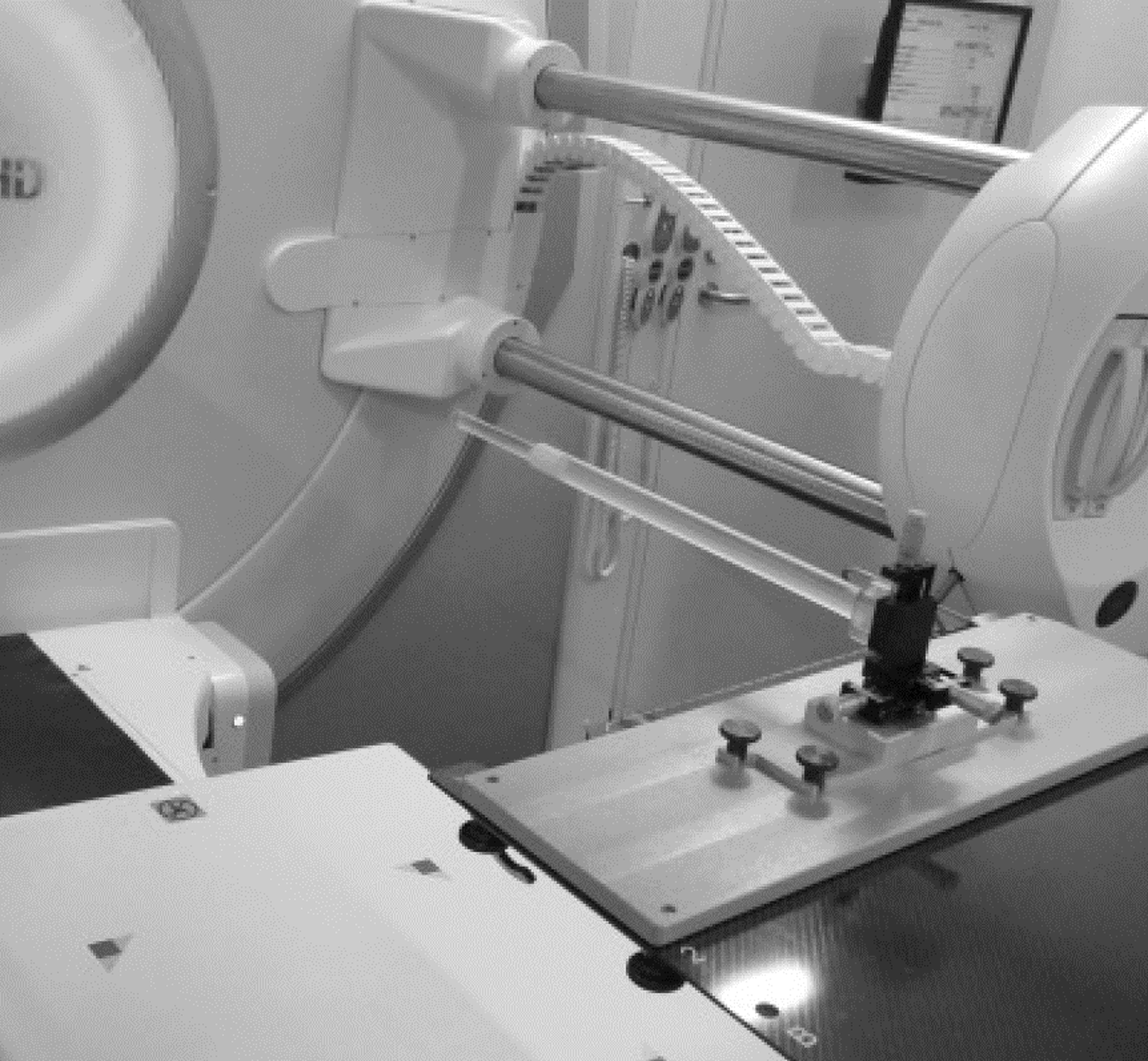
Figure 1. Setup for Winston–Lutz test. An X-ray opaque sphere is placed at the isocenter, and X-rays are irradiated from several gantry angles.
The radiation isocenter position for each energy was calculated, referring to the assessment method of beam alignment between energies using BB by Zhang.Reference Zhang, Ding and Cowan12 From the central coordinates of the BB on the image, the radiation isocenter position for each energy and dose rate was calculated in the lateral (LAT), gun-target (GT), and Up–Down directions. The three-dimensional movement of the isocenter due to the dose rate was then calculated based on the maximum dose rate for each energy. The maximum dose rate was used as a reference because it is predominantly used for QA. In this study, we considered the R and G directions as the positive (+) direction and the L and T directions as the negative (−) direction. The left–right (LR) directions follow the notation in IEC (61,217).13
Measurement of irradiation field centre position by a three-dimensional water phantom
Profile measurements were conducted using a three-dimensional water phantom, blue phantom2 (IBA dosimetry, Schwarzenbruck, Germany), to assess the beam alignment based on a beam axis of 6 MV of 500 MU/min. A cylindrical CC13 ionisation chamber (IBA dosimetry) was utilised. The LAT and GT off-axis ratio (OAR) were measured three times at peak depth, 100 mm, 200 mm and 300 mm depths for each X-ray energy and dose rate. Peak depth indicates the depth of the maximum dose. The source-surface distance was 1000 mm, and the irradiation field size was 10 × 10 cm2. The centre position of each irradiation field was calculated from the OAR data using the analysis software my QA accept version 7·5 (IBA dosimetry).
Assessment of VMAT plans using a three-dimensional detector
Computed tomography images that depict the planning target volume (PTV) and normal organs for commissioning as indicated by AAPM TG-119Reference Ezzell, Burmeister and Dogan14 used two patterns in this study—one that mimics the pelvic region, including the prostate (mock_prostate), and another that mimics the head and neck (mock_HN). Each plan was developed to meet the dose constraints provided in TG-119. Plans established by mock_prostate and mock_HN were denoted as ‘prostate plan’ and ‘H and N plan’, respectively.
After loading each plan into the treatment machine, DD changes were assessed using ArcCHECK (Sun Nuclear, Melbourne, USA), which is a three-dimensional detector, using a beam that reproduces the beam axis shift that occurs when the dose rate is changed.
The bending magnet of Versa HD demonstrates a slalom structure and changes the direction of electrons downward by combining 45° down, 45° up and 112·5° down deflections. The position of the radiation isocenter is adjusted for each energy using the parameters of the steering coil and bending magnet,Reference Paynter, Weston and Cosgrove15 and the bending F parameter is utilised to move the electron target incidence position in the GT direction during the 112·5° deflection.Reference David16 The beam axis deviation caused by dose rate change was reproduced through parameter adjustments based on the original bending F values of 1·7 and 2·07 for the 6 MV and 6 MV FFF, respectively. The unit of the bending F parameter is A (ampere).
Results
WL test
Figure 2 illustrates the WL test result using multiple energies (4 MV, 6 MV, 10 MV, 6 MV FFF and 10 MV FFF) at different dose rates. The result of the WL test indicated that the radiation isocenter varied based on the energy and dose rate. The WL test is a method for assessing the radiation isocenter; however, it includes gantry sagging and geometric rotation accuracy. We conducted WL tests on CW. Considering that the gantry rotates 360 degrees, it should return to the starting point, but returning to the same place is difficult.
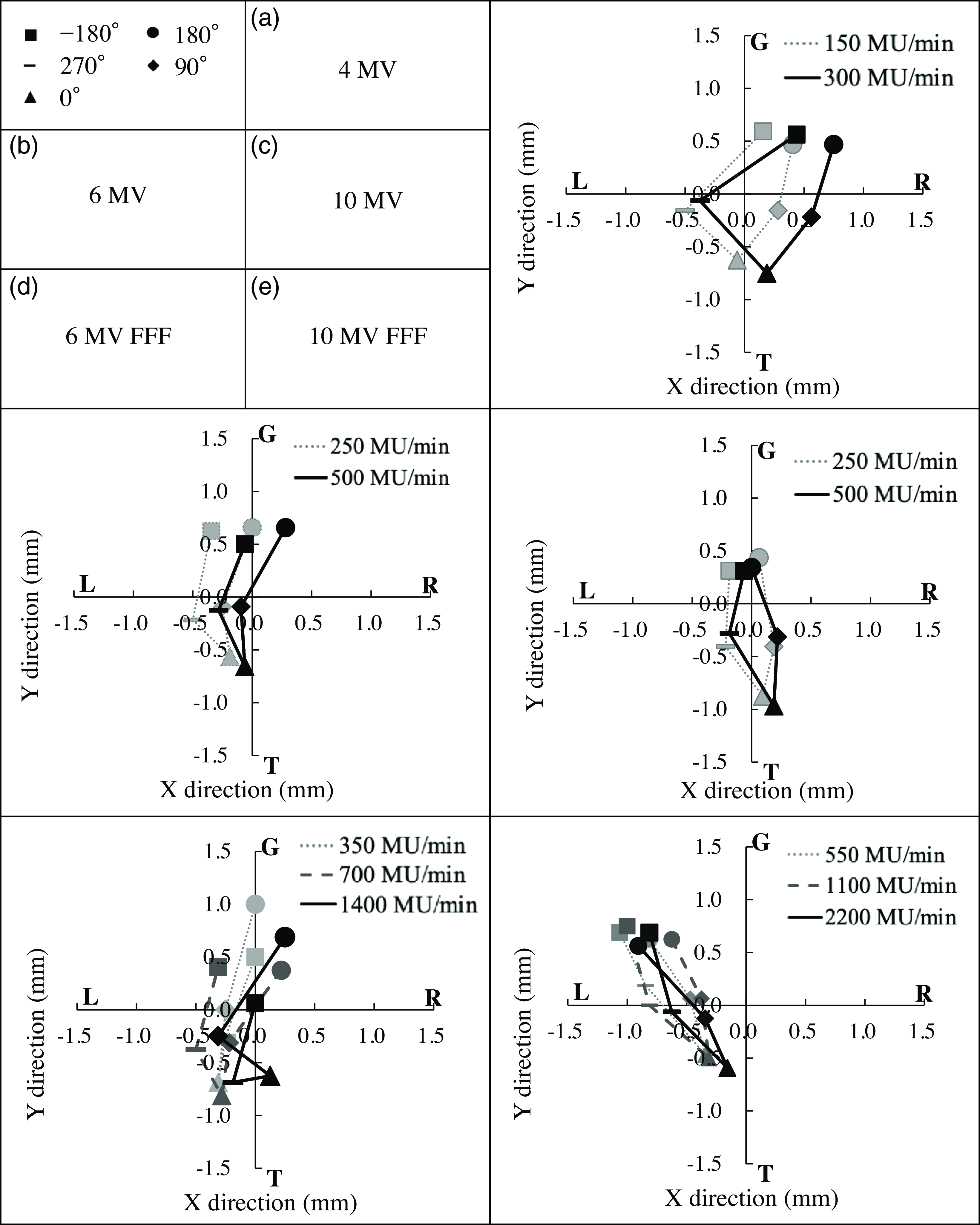
Figure 2. Winston–Lutz test results at various dose rates and energies. X-rays were irradiated at gantry angles of −180°, 270°, 0°, 90° and 180° to a ball bearing, and electronic portal imaging device was used to acquire images. The results were different not only according to the energy but also the dose rate. R, G: + side, L, T: − side.
Figure 2 illustrates the positional relationship between the centre of the image and the BB using two-dimensional images obtained from the WL test. The 0° and 180° images show the positional deviation in the LAT and GT directions, and 90° and 270° images show the Up and Down information, which is calculated as shown in Table 1.
Table 1. Displacement of radiation isocenter by dose rate
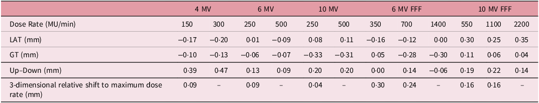
In the RL direction, L indicates the − side and R denotes the + side, and in the GT direction, G represents the + side and T demonstrates the – side.
Table 1 presents the position of the radiation isocenter at each energy and dose rate, and the displacement calculated based on the maximum dose rate for each energy. Relative shift to maximum dose rate shows a three-dimensional distance calculated from LAT, GT and Up–Down. WL test convolves multiple errors, such as gantry, collimator and couch axes. However, the relative shift is based on the maximum dose rate; thus, these errors can be ignored.
The radiation isocenter displacement by dose rate was within 0·1 mm at 4, 6 and 10 MV and 0·1∼0·3 mm at 6 and 10 MV FFF.
Measurement of irradiation field centre position using a three-dimensional phantom
Figure 3 illustrates the results of the irradiation field centre at 4, 6 and 10 MV nominal energies for various dose rates, and Figure 4 demonstrates those at 6 and 10 MV FFF. The beam centres of the 4, 6 and 10 MV beams demonstrated an up to 0·37 and 0·47 mm beam centre position displacement in each LAT and GT direction due to the change in the energy and dose rate.

Figure 3. Change of beam centre at multiple dose rates and depths for 4, 6 and 10 MV beams. Measurement peak depths were measured at peak, 100 mm, 200 mm and 300 mm. The off-axis ratio measurements were conducted at multiple energies and dose rates, and the beam centre displacement was observed not only by the energy but also by the dose rate. Scan direction: (a) LAT (L: − side, R: + side), (b) GT (T: − side, G: + side).
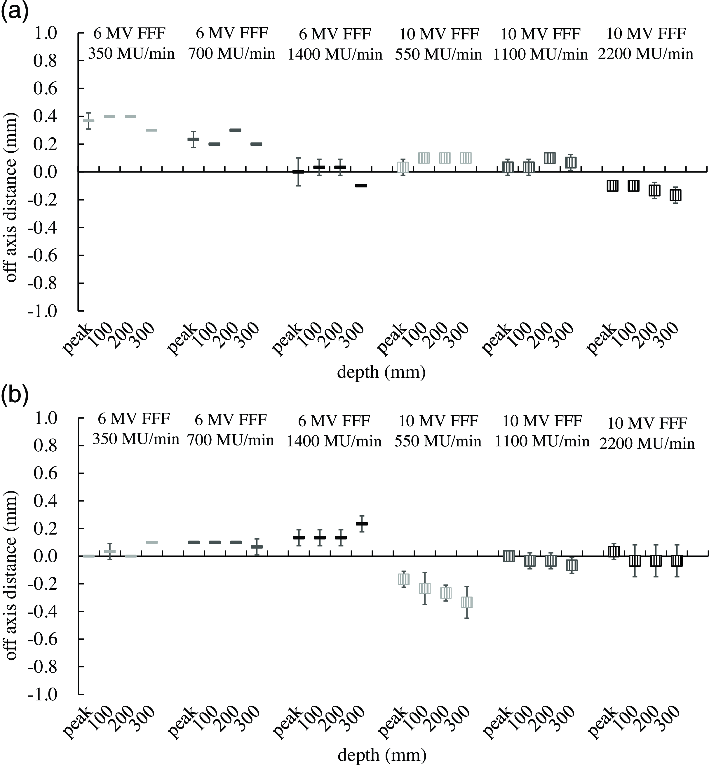
Figure 4. Change of beam centre at multiple dose rates and depths for 6 and 10 MV flattening filter-free (FFF) beams. The off-axis ratio measurements were conducted at FFF multiple energies and dose rates. Similar to the FF beam, the beam centre displacement was observed not only by the energy but also by the dose rate. Scan direction: a LAT (L: − side, R: + side), b GT (T: − side, G: + side).
The beam centre position in the LAT direction for the 6 MV FFF beam at 350, 700 and 1400 MU/min was 0·37, 0·23 and 0·0 mm at peak depth, respectively. The depth variation was within 0·1 mm. The beam centres in the GT direction at 550, 1100 and 2200 MU/min of 10 MV FFF were −0·17, 0·00 and 0·03 mm at peak depth, whereas the centre positions at 300 mm depth were −0·33, −0·07 and −0·03 mm, respectively. The beam centre displacements at peak depth in the GT direction were within 0·13 mm for 6 MV FFF at all dose rates used in this study. The beam centre displacements were within 0·17 mm at all depths in both LAT and GT directions for 10 MV FFF at 1100 and 2200 MU/min.
Evaluation of VMAT plan using a three-dimensional water phantom
The clinical impact of the beam centre position shift of 0·2–0·4 mm was assessed because the dose rate was dependent on the beam centre position. The energy used was 6 MV, which is the energy frequently applied in radiotherapy.
Adjusting the bending F parameter can move the electron target incidence position in the GT direction. Bending F parameter adjustment was performed to reproduce the change in the beam centre position due to the change in dose rate. The result revealed a 0·2–0·4 mm change in the beam centre at the bending F parameter of 1·80 (original: 1·70) for 6 MV and 2·27 (original: 2·07) for 6 MV FFF. OAR measurements in the GT direction were performed with multiple bending F parameters to understand the relationship between the bending F parameter and the beam centre position. The beam centre displacement was 0·2–0·4 mm in the case of bending F parameter 1·8 at 6 MV and 2·27 at 6 MV FFF (Figure 5).
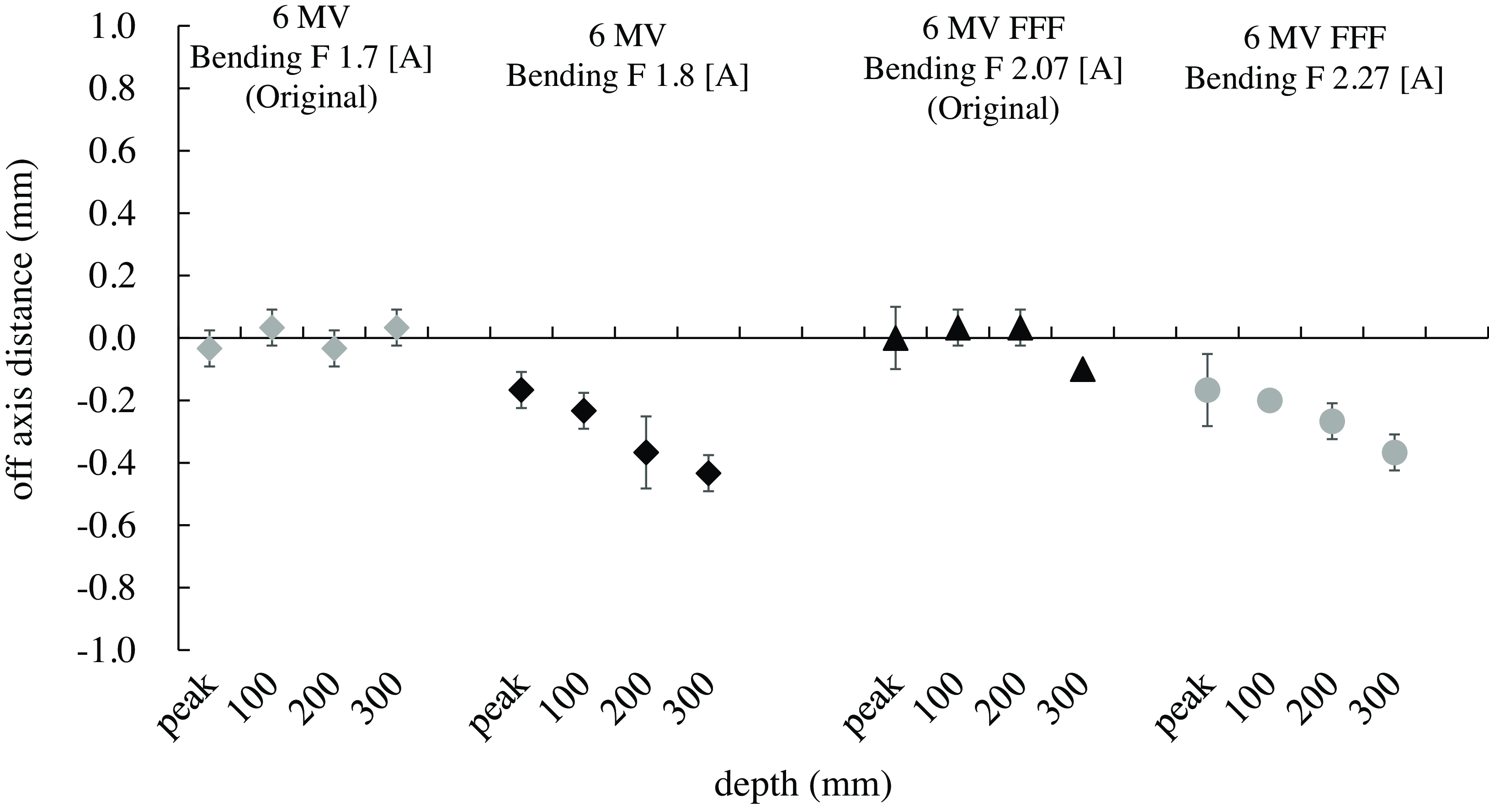
Figure 5. Change of beam centre at multiple bending F parameters (GT direction). The GT direction off-axis ratio measurements were conducted based on bending F parameters. The beam centre displacement was 0·2–0·4 mm in the case of bending F parameter 1·8 at 6 MV and 2·27 at 6 MV flattening filter-free. Scan direction: T: − side, G: + side.
The IMRT plan established concerning TG119 was irradiated to ArcCHECK with each bending F parameter. Table 2 presents the results of comparing the pass rate (threshold: 3%) of DD based on the original parameters.
Table 2. Variation of dose difference (DD) pass rate with changing beam centre
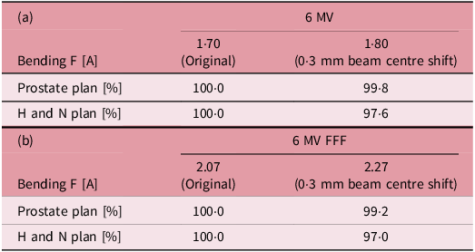
Changes in the DD were assessed with a three-dimensional detector using a beam that reproduced the beam axis shift that occurs when the dose rate is changed. Photon beam: a 6 MV, b 6 MV flattening filter-free.
The change in DD pass rate was within 1% in the prostate plan, whereas the pass rate decreased by 2·4% in the 6 MV plan and by 3·0% in the 6 MV FFF plan in the H and N plans.
Discussion
The WL test demonstrated a measurement accuracy of 0·1 mm.Reference Stephen, Jimmy and Nathan11 The blue phantom2 utilised in the measurements is a device that has been certified with an operating accuracy of ±0·1 mm. Therefore, the measurement accuracy of 0·1 mm is guaranteed in this study. The original data were measured, and only the beam parameters were changed without touching the device; thus, the position error when setting up the device can be ignored.
In 2015, Zhang et al. revealed different beam alignments and radiation isocenters according to the energy by measuring the beam profile and conducting the WL test using multiple beam energies.Reference Zhang, Ding and Cowan12 This study revealed similar changes with energy as well as alterations in radiation isocenter and beam centre axis with dose rate.
Electrons emitted from the electron gun and injected into the accelerator tube change their motion direction downward by the bending magnet and are transformed into an X-ray beam by being injected into the target. At this point, the electrons attempt to diverge due to repulsive forces caused by their mutual negative charges. To prevent this, coils are placed around the accelerator tube to converge the electrons. The convergence and direction-changing forces of the electrons differ with energy, and the coil parameters vary with each energy. If the energy is the same despite different dose rates, the number of electrons per pulse is constant. However, the difference in pulse spacing influences the convergence and direction of electrons; thus, beam control may become uncertain when the same parameters are used for control. The displacement of the radiation isocenter was larger for the FFF beams than for the FF beams. WL test is conducted at low MU irradiation, which may cause an unstable beam. The FFF dose rate was 3–4 times higher than that for the FF beams, so the effect of this may have been significant.
The beam centre displacement caused changes in flatness and symmetry as well as irradiation field misalignment.Reference Karzmark, Numan and Tanabe17 The 0·2–0·4 mm displacement of the beam centre can be ignored for a large irradiation field, but it can affect the dose error for a small irradiation field. The small irradiation field shaped by the MLC is integrated to produce the desired intensity dose distribution in IMRT. The head and neck VMAT plan is more complex than that of the prostate and is performed by accumulating smaller irradiation fields; thus, the change in the DD pass rate is more pronounced in the H and N plan than in the prostate plan. Flatness and symmetry are unlikely to occur in the case of FFF since the beam does not pass through an FF.Reference Paynter, Weston and Cosgrove15 However, the dose distribution is convex; thus, the change in the centre position has a large effect on the dose concentration in the PTV, which may decrease the pass rate compared to the FF beam.
The limitation of this study includes the use of a single device, which may demonstrate various deviations based on the systems, so measurements should be performed using multiple models and devices. However, the isocenter and beam centre predominantly change depending on the dose rate, and this warrants verification at each facility.
Conclusions
This study confirms that varying dose rates displace the radiation isocenter and beam centre. Changes in beam alignment at different dose rates should be assessed, as this could improve the precision of radiation therapy. Conducting QA at multiple dose rates will enhance the accuracy of radiotherapy in the future.
Acknowledgements
We thank the Radiology Department of Jichi Medical University Saitama Medical Center for their cooperation in the measurements. I would like to express my gratitude to Company ENAGO for their assistance in the English proofreading of this paper.
Financial support
No funding has been received from companies or academic societies in connection with this study.
Competing interests
The authors have no relevant conflicts of interest to disclose


 Open access