

Introduction
High-quality proton beams produced by laser-driven thin solid foils (Refs Reference Bai, Zhou, Huang, Jiang, Ju, Li, Peng, Yu, Qiao, Ruan and He1–Reference Yang, Zhou, Huang, He, Wu, Cai, Qiao, Yu, Ruan and He6) can be used in various fields such as proton therapy (Refs Reference Linz and Alonso7, Reference Smith8), proton imaging (Ref. Reference Wang, Dong, Shi, Jiang, Xu, Zhang, Wu, Hu, Qian, Zhu, Liang, Leng, Li and Xu9) and fast ignition of inertial confinement fusion (Ref. Reference Naumova, Schlegel, Tikhonchuk, Labaune, Sokolov and Mourou10). Several mechanisms have been proposed for energetic proton generation, such as radiation pressure acceleration (RPA) (Refs Reference Esirkepov, Borghesi, Bulanov, Mourou and Tajima11–Reference Qiao, Zepf, Borghesi, Dromey, Geissler, Karmakar and Gibbon14), collisionless shock acceleration (CSA) (Ref. Reference Silva, Marti, Davies, Fonseca, Ren, Tsung and Mori15), target normal sheath acceleration (TNSA) (Ref. Reference Wilks, Langdon, Cowan, Roth, Singh, Hatchett, Key, Pennington, MacKinnon and Snavely16), breakout afterburner acceleration (Ref. Reference Yin, Albright, Hegelich and Fernández17) and other combined mechanisms (Refs Reference Higginson, Gray, King, Dance, Williamson, Butler, Wilson, Capdessus, Armstrong, Green, Hawkes, Martin, Wei, Mirfayzi, Yuan, Kar, Borghesi, Clarke, Neely and McKenna18, Reference Henig, Kiefer, Markey, Gautier, Flippo, Letzring, Johnson, Shimada, Yin, Albright, Bowers, Fernandez, Rykovanov, Wu, Zepf, Jung, VKh Liechtenstein, Habs and Hegelich19). To date, TNSA is still considered the most robust acceleration mechanism for obtaining ∼100 MeV proton beams (Ref. Reference Hornung, Zobus, Boller, Brabetz, Eisenbarth, Kühl, Zs Major, Zepf, Zielbauer and Bagnoud20). However, these ion beams typically exhibit broad energy spectra or large beam divergence, limiting their direct application in fields like proton therapy (Refs Reference Linz and Alonso7, Reference Smith8). To address this, a cascaded acceleration mechanism based on the robust TNSA mechanism has been developed (Refs Reference Pfotenhauer, Jäckel, Polz, Steinke, Schlenvoigt, Heymann, Robinson and Kaluza21–Reference Wang, Shen, Zhang, Lu, Li, Zhai, Li, Wang, Xu, Wang, Leng, Liang, Li and Xu23), where a sheath field generated on a second target tailors the spectra and maximum energy of the incident proton beam from the first acceleration stage (Refs Reference Wang, Shen, Zhang, Lu, Li, Zhai, Li, Wang, Xu, Wang, Leng, Liang, Li and Xu23, Reference Wang, Weng, Liu, Chen, He, Zhao, Murakami and Sheng24).
However, the previous cascaded mechanisms were inefficient because only a small fraction (usually ≪10%) of the incident proton beam from the first stage is accelerated by the finite static sheath field driven by the small focal spot of the second laser on the second target (Refs Reference Wang, Shen, Zhang, Lu, Li, Zhai, Li, Wang, Xu, Wang, Leng, Liang, Li and Xu22, Reference Sun, Wang, Dong, He, Shi, Leng, Li and Xu25). Recently, Kar et al. proposed a post-processing scheme by using a femtosecond (fs) laser to drive a metallic foil attached to a solenoid to improve the cascaded acceleration efficiency. The main reason is that the electromagnetic pulse (EMP) driven by the laser on the solenoid can synchronise with the incident protons under an optimal space–time condition to further accelerate and collimate the incident proton beam for a longer time and larger distance (Refs Reference Sun, Wang, Dong, He, Shi, Leng, Li and Xu25–Reference Liu, Mei, Kong, Pan, Shirui, Gao, Shou, Wang, Cao, Liang, Peng, Zhao, Chen, Song, Chen, Xu, Yan and Ma31). However, since the solenoid is directly connected to the target’s back, it limits the ability to flexibly tune the parameters of the incident protons and the solenoid independently, resulting in the limited tuning for the energy, spectra and divergence of the proton beam. Therefore, separating the solenoid from the target may be an efficient method to potentially introduce more innovations to the present cascaded solenoid acceleration mechanism.
In this article, we present an actively controllable cascaded proton acceleration mechanism driven by a separated picosecond (ps) laser in experiments. It is found that an fs-laser irradiates the target to generate MeV protons in the first stage, which are further tuned by an EMP on an independent solenoid irradiated by another ps laser in the second stage. An electrodynamics model is carried out to explain the experimental results, showing that the proton beam can be shaped into ring and dot forms by appropriately tuning the EMP strength on the solenoid, which is consistent with the experimental results. The proton beam shapes tailored in our ps-laser-driven cascaded solenoid acceleration mechanism offer a convenient and controllable method for creating structured proton beams for special applications. For instance, the ring proton beam can enhance edge-imaging in proton radiography for expanding plasma and capsule implosions in confined fusion, while the collimated proton beam can be used for proton therapy.
Experimental setup
The experiment was conducted at the XingGuang-III laser facility in the Laser Fusion Research Center (see Fig. 1a). An ∼8 J fs laser with a wavelength of 800 nm and a duration of ∼50 fs irradiated a 10 μm thick copper target, accelerating a proton beam via the TNSA mechanism in the first stage. In the second stage, a ps laser with ∼30 J to ∼120 J energy and ∼800 fs duration (full width at half maximum (FWHM)) was focused onto a 500 μm thick copper foil. One side of a folded wire was connected to the foil back, and the other side to the ground, generating an EMP towards the ground when the ps laser irradiated the copper foil. The resulting longitudinal and transverse electric fields in the solenoid centre moved forward, continuously accelerating and concentrating the proton beam. The radii of the fs and ps laser focal spots were ∼10 μm and ∼20 μm, respectively, with about 30% of laser energy enclosed within the FWHM of the focal spots. This corresponds to intensities of ∼6.1 × 101⁹ W/cm2 for the fs laser and ∼3.6 × 10¹⁸ W/cm2 to ∼1.4 × 10¹⁹ W/cm2 for the ps laser.
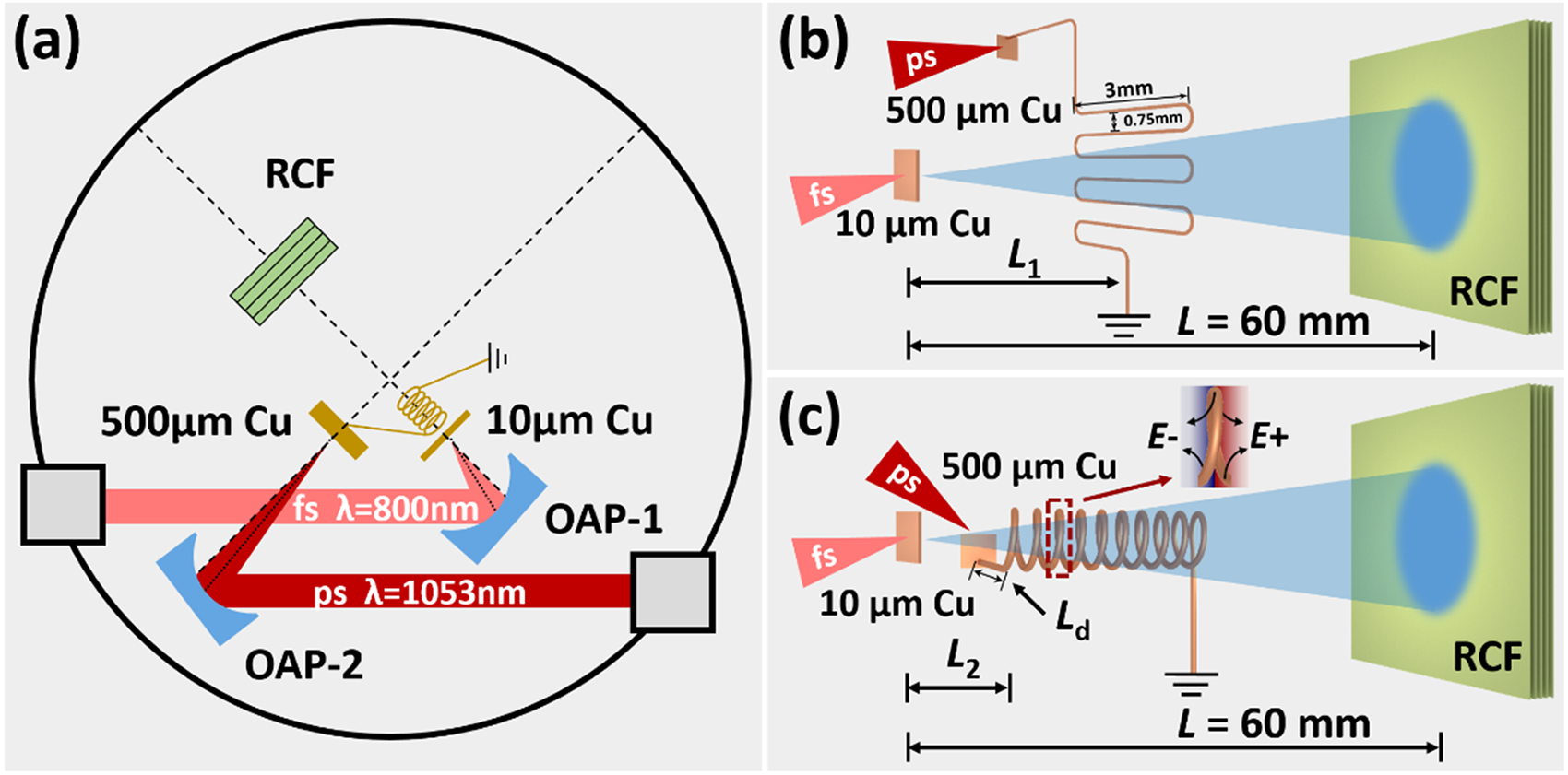
Figure 1. (a) Experimental setup. The fs laser drives a 10 μm copper to generate a proton beam, and the ps laser drives a 500 μm copper to generate an EMP to modulate the proton beam. (b) Proton imaging setup. The diameter of the folded copper wire was 0.1 mm, with a width of ∼3 mm and a vertical spacing of ∼0.75 mm between wires. (c) Active-controlled cascaded proton acceleration setup. The solenoid was constructed with 0.1 mm diameter copper wire, with an inner diameter of ∼0.7 mm, a pitch of ∼0.3 mm, 10 turns, and an overall length of ∼3 mm.
To investigate the effects of the ps-laser-driven solenoid on cascaded proton tailoring, a proton radiograph for the EMP was conducted in Fig. 1b. An fs laser irradiated a separate 10 μm thick copper foil to generate a proton beam to probe the EMP on the folded wire. The 10 μm copper foil was placed at a distance of L 1 = 6 mm from the folded wire plane and L = 60 mm from the radiochromic film (RCF) stack, providing a magnification of M = 10 on the RCF stacks. The probing beam was oriented perpendicular to the folded wire plane and could be deflected mainly by the electric field on the wire (Ref. Reference Ehret, Bailly-Grandvaux, Ph Korneev, Brabetz, Morace, Bradford, d’Humières, Schaumann, Bagnoud, Malko, Matveevskii, Roth, Volpe, Woolsey and Santos32). By analysing the redistribution of the proton beam on the RCFs, the EMP strength was calculated to understand its effects on proton beam shapes when the folded wire was replaced with a solenoid.
Then, the cascaded solenoid acceleration was implemented by replacing the folded wire with the solenoid in Fig. 1c. The ps-laser energy was increased to ∼120 J to drive a stronger EMP on the solenoid. By adjusting L 2 (the distance between the 10 μm Cu foil and the front of the solenoid) and L d (the length of the 500 μm Cu foil and the solenoid connection line), the simultaneous arrival of the proton beam and EMP at the solenoid can be achieved. The EMP propagating along the solenoid forms a helical electric field, exerting a repulsive force on the proton beam and altering its direction and speed.
Experimental results
Figure 2a shows the proton imaging of the copper wire without EMP, where the copper wire width of 1 mm is obtained on RCF. When a ∼37 J ps laser is introduced in the second stage, the width of the copper wire increases significantly because the incident proton beam from the first stage is dispersed by the EMP moving along the copper wire, see Fig. 2b and c. By analysing the position of the EMP, its propagating velocity (∼0.95 c) can be calculated, which is consistent with previous research (Refs Reference Quinn, Wilson, Cecchetti, Ramakrishna, Romagnani, Sarri, Lancia, Fuchs, Pipahl, Toncian, Willi, Clarke, Neely, Notley, Gallegos, Carroll, Quinn, Yuan, McKenna, Liseykina, Macchi and Borghesi33, Reference Ahmed, Kar, Cantono, Nersisyan, Brauckmann, Doria, Gwynne, Macchi, Naughton, Willi, Lewis and Borghesi34).
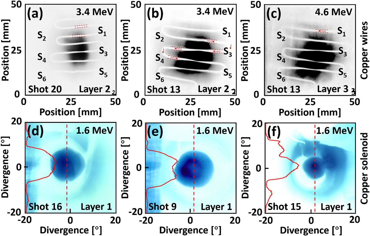
Figure 2. (a) Proton beam imaging result without EMP and (b, c) with EMP. The fs laser energy is ∼7 J for both shot 20 and shot 13. The ps laser energy was ∼37 J for shot 13. The red arrow indicates the EMP propagation direction. (d) Proton beam acceleration result without EMP. (e, f) Proton bunching results of ring and dot with EMP. The ps laser energy was ∼114 J for shot 9 and ∼37 J for shot 15. The red curve in (d–f) shows the normalised greyscale distribution along the red dotted line.
According to the EMP velocity and position, we performed the cascade acceleration experiment (see Fig. 1c). Initially, the solenoid is imaged by a 3.4 MeV proton beam from the first stage driven by the 7.7 J fs laser, while the ps laser does not work in Fig. 2d. It can be found that the solenoid separates the incident proton beam into inner and outer regions and the protons distribute uniformly inside the solenoid. In contrast, the 1.6 MeV proton beam with a ring structure was obtained by a ∼114 J ps laser irradiating on the solenoid in the second stage in Fig. 2e, where the EMP is generated on the solenoid and manipulates the incident protons inside. It is interesting that the proton structure can transform from ring to dot by reducing the ps laser energy from 114 J down to 37 J (see Fig. 2f). It indicates that proton beam structure can be simply controlled by the EMPs driven by ps lasers with different laser energies or intensities (Refs Reference Kar, Ahmed, Prasad, Cerchez, Brauckmann, Aurand, Cantono, Hadjisolomou, Lewis, Macchi, Nersisyan, Robinson, Schroer, Swantusch, Zepf, Willi and Borghesi26, Reference Ahmed, Hadjisolomou, Naughton, Alejo, Brauckmann, Cantono, Ferguson, Cerchez, Doria, Green, Gwynne, Hodge, Kumar, Macchi, Prasad, Willi, Borghesi and Kar29, Reference Bardon, Moreau, Romagnani, Rousseaux, Ferri, Lefévre, Lantuéjoul, Etchessahar, Bazzoli, Farcage, Maskrot, Serres, Chevrot, Loyez, Veuillot, Cayzac, Vauzour, Boutoux, Sary, Compant La Fontaine, Gremillet, Poyé, Humiéres and Tikhonchuk30, Reference Aktan, Ahmed, Aurand, Cerchez, Poyé, Hadjisolomou, Borghesi, Kar, Willi and Prasad35), which will be explained in the following theoretical calculations.
It is important to note that during the preparation of the experiment, we focused on imaging the proton beam on the RCF. We can estimate the maximum cut-off energy of the proton beam by counting the number of RCF pieces. Figure 3 presents a comparison of two proton acceleration results. Shot 9 was conducted with a ps laser, while shot 10 utilised a separate fs laser. As shown in the comparison, the introduction of the EMP not only enhances the convergence of the proton beam but also leads to an increase in the highest energy order of the proton beam. In future studies, we will explore methods to measure the energy spectrum of the proton beam without compromising the imaging process.
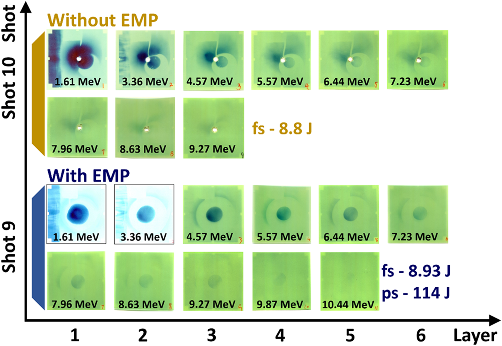
Figure 3. Comparison of the influence of EMP on the proton acceleration.
Modelling and analysis
To calculate the intensity and pulse width of the EMP generated by a ps laser, a proton deflection model was developed based on the theory in reference (Ref. Reference Ehret, Bailly-Grandvaux, Ph Korneev, Brabetz, Morace, Bradford, d’Humières, Schaumann, Bagnoud, Malko, Matveevskii, Roth, Volpe, Woolsey and Santos32), as shown in Fig. 4a. The electrostatic field  $\overrightarrow E $ in the x–y plane (z = 0 μm) is expressed as
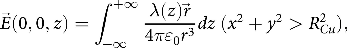 \begin{equation}\overrightarrow E ({\text{0}},{\text{0}},z) = \int_{ - \infty }^{ + \infty } {\frac{{\lambda (z)\overrightarrow r }}{{4\pi {\varepsilon _0}{r^3}}}} dz{\text{ }}({x^2} + {y^2} \gt R_{Cu}^2),\end{equation}
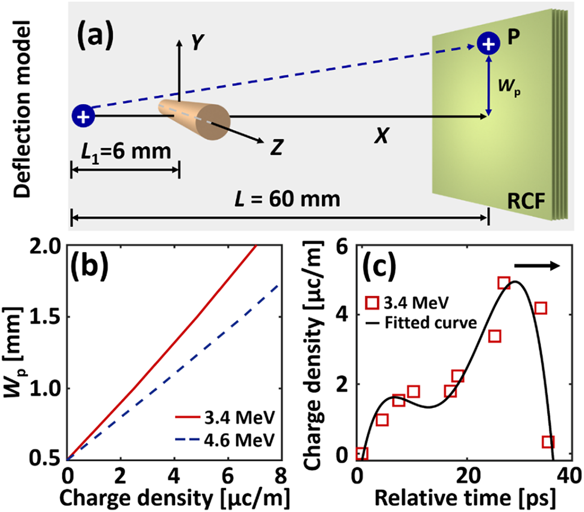
Figure 4. (a) Proton deflection model. (b) Relationship between the charge density and the deflection distance. Here, the solid red line indicates 3.4 MeV, and the blue dotted line indicates 4.6 MeV. (c) Charge density and the relative time calculated from the experimental results. The measured value is the width of the wire at different locations on the RCF. The red squares are the measured values. The solid black line is the fitting curve. The black arrow indicates the direction of EMP propagation.
where ε 0 is the permittivity constant of vacuum,  $\overset{\rightharpoonup}{r}$ is the radius away from the wire centre (0, 0, z). Then, a single proton is incident from the position (−L 1, 0, 0) and is influenced by the electrostatic field from the wire, described by a dynamic equation as
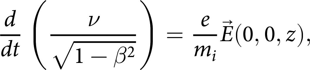 \begin{equation}\frac{d}{{dt}}\left( {\frac{\nu }{{\sqrt {1 - {\beta ^2}} }}} \right) = \frac{e}{{{m_i}}}\overrightarrow E ({\text{0}},{\text{0}},z),\end{equation}
where e is the electron charge, m i is the ion mass, and β = v/c is the dimensionless velocity vector. It is assumed that the protons reach the RCF stacks in the experiment when x = L − L 1 is obtained. The deflection distance (w p) is proportional to the charge density, with lower-energy protons deflecting a greater distance at the same charge density, as shown in Fig. 4b. A ∼20 ps temporal profile of the charge pulse can be reconstructed in Fig. 4c by calculating w p at different positions along the solenoid in Fig. 2b and c), which is roughly consistent with previous parameters under similar experimental conditions (Ref. Reference Kar, Ahmed, Prasad, Cerchez, Brauckmann, Aurand, Cantono, Hadjisolomou, Lewis, Macchi, Nersisyan, Robinson, Schroer, Swantusch, Zepf, Willi and Borghesi26). It should be noted that the shape of the EMP pulse excited by the ps laser differs slightly from that excited by the fs laser, and there remains a high charge density at the tail. However, the peak charge density of ∼4.9 μC/m is much lower, possibly because a thicker Cu foil (500 μm) and lower ps laser energy (∼37 J) are used in our case.
We establish a simple electrodynamic model to analyse the specific process of proton beam converging into different structures under the action of EMP, as shown in Fig. 5a. In this model, two-point charges, spaced 0.7 mm apart, simulate the two-dimensional electric field distribution when the EMP moves in the solenoid. The quantity of the point charge Q is ∼1.4 × 10⁻11 C, which is calculated by the model in Fig. 4a. The x-direction velocity component of the EMP moving through the solenoid V EMP is ∼3.4 × 10⁷ m/s, which can be calculated by the velocity of the EMP propagating through the wire, the inner diameter of the solenoid and the pitch of the solenoid. Between the two-point charges is a group of evenly distributed protons, and according to the experimental results, the proton divergence is approximately ∼14°. In our case, we simulate 9 protons and do not take into account the repulsion between protons. The protons start at the same position as the two-point charges and move forward in the x-direction with different speeds. Since the clearest results obtained from the experiment correspond to a 1.6 MeV proton beam, we set V p in the model to ∼1.75 × 10⁷ m/s to match the speed of the 1.6 MeV proton beam. Figure 5b presents the results of the dot proton beam obtained through model simulation, where Q is set to ∼1.4 × 10⁻Reference Esirkepov, Borghesi, Bulanov, Mourou and Tajima11 C. As seen in Fig. 5b, the edge of the proton beam is influenced by the electric field and converges towards the centre, eventually forming a dot density distribution at 60 mm, similar to the experimental result in Fig. 2f. Furthermore, a ring density distribution is observed in the proton beam in Fig. 5c, where Q is set to 2 × 10⁻11 C, resembling the experimental results in Fig. 2e. It should be noted that, due to computational limitations, our simulation used only 9 protons to model the distribution trend, which is significantly different from experimental conditions. Furthermore, our simplified electrodynamic model did not account for the repulsive forces between protons or the magnetic field produced by the EMP. The simulation results primarily highlight the impact of EMP intensity on the spatial distribution of proton beams. Both experimental and simulation results show that the spatial distribution of proton beams can be modulated by controlling the EMP intensity. In the follow-up research work, we will further improve the model to make it more realistic to explain the experimental results.

Figure 5. (a) Electrodynamic model. (b, c) The simulation results of the ring and dot proton beams in a 60 mm simulated domain are similar to the experimental results.
Summary
In this article, we propose an active-controllable cascaded proton acceleration mechanism to modulate fs laser proton beams by directing the EMP generated by a ps laser via a solenoid. In the experiment, EMP was initially captured using proton imaging. Subsequent measurements and calculations revealed that the EMP had an FWHM of ∼20 ps, with a peak intensity of ∼4.9 μC/m. The solenoid then directed an EMP to effectively shape the proton beam, resulting in the successful generation of both ring and dot configurations of the proton beam. Based on the experimental setup, we established a simple electrodynamics model to analyse the experimental results. Our experimental results and simulations have shown that the shape of the proton beam is closely related to the EMP emission. This active-controllable cascaded proton acceleration mechanism can independently adjust the proton beam and EMP, providing a wider adjustment range than the single-beam laser drive method. It offers a solution to produce special-shaped proton beams required in various applications. For example, the ring proton beam has the potential to enhance edge-enhanced proton radiography, such as in expanding plasma studies, while the dot proton beam with lower divergence is of great interest in proton therapy and other fields.
Data availability statement
The data that support the findings of this study are available within the article.
Acknowledgements
This work was supported by the Strategic Priority Research Program of the Chinese Academy of Sciences (Grant No. XDA0380000), Science and Technology Commission of Shanghai Municipality (Grant No. 22DZ1100300), International Partnership Program of Chinese Academy of Sciences (Grant No. 111GJHZ2022029FN), National Natural Science Foundation of China (Grant No. 12388102).
Author contributions
The authors contributed equally to this work.
Conflict of interest
The authors have no conflicts to disclose.


 Open access