

The brain as an information processor
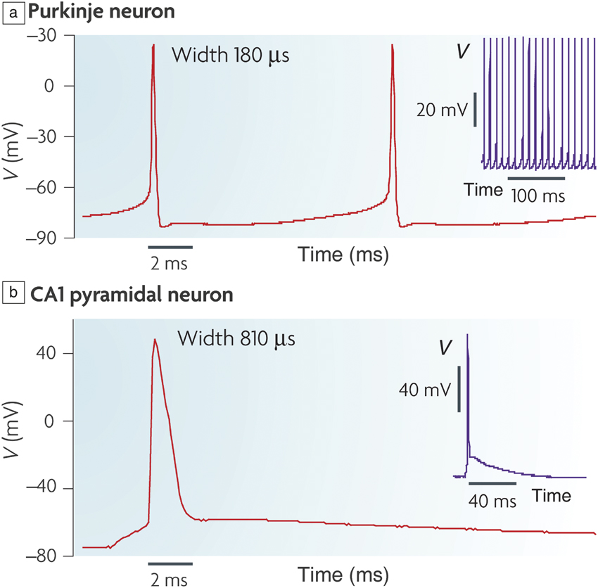
A key function of the brain is to process a multitude of information received through various sensory inputs and make informed decisions. This occurs via two critical components—the neuron and the synapse. A neuron may be simply considered as a cell that transmits nerve impulses in the form of electrical signals, while a synapse is a junction between nerve cells with programmable resistance. The number of neurons, synapses, and their interconnections can vary by several orders of magnitude, depending on the organism. For instance, the mouse has approximately 70 million neurons, while humans have more than 85 billion neurons.Reference Herculano-Houzel1 A small subset of neurons (few to dozens) in a circuit are utilized to process specific types of information or evoke responses to specific stimuli. Common features of neurons across animal species do exist, forming the basis for much neuroscience research. Neurons transmit information via electrical signals known as action potentials.Reference Bean2 These are in the form of electrical spikes (Figure 1). While there exist several types of neurons with varying structure and interconnections, called neural circuit pathways, and physical locations in the brain or elsewhere in the body, they do share similarities in the form of action potentials used to transmit information. The typical voltage spikes are on the order of 100 mV in neuronal signals and time scales are on the order of milliseconds.Reference Kandel, Schwartz and Jessell3 Among the distinct neuron types, there can be a distribution in the magnitudes and spike time widths. The time scales for signaling in the brain are clearly much slower than transistor switching speeds or interconnect wire delays in state-of-the-art computer chips. Yet, the brain possesses capabilities unmatched by any computer to date for certain tasks, and this serves as one motivation to design the next generation of machines that can evolve and learn like the brain, in addition to being energy efficient.Reference Laughlin and Sejnowski4 Adaptive and programmable materials are therefore of great interest in this context.
(a) Action potential (V) in a mouse Purkinje neuron that is located in the cerebellum; inset shows periodic spikes in time. (b) Action potential in a mouse brain slice from a hippocampal CA1 pyramidal neuron; inset shows single spiking event over several tens of microseconds time scale. The voltage spike profile, width, and firing frequency depends on the neuron type. Reprinted with permission from Reference Reference Bean2. © 2007 Nature Publishing Group.
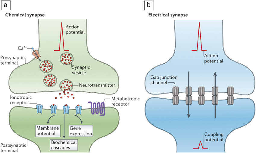
Synapses serve to weigh the effective strength of signals transmitted by neurons as they propagate to other neuron branches. Synapses can gate the signals via electrical or chemical mechanisms (Figure 2). Electrical synapses transmit information rapidly (milliseconds), while chemical synapses can be a few orders of magnitude slower (seconds). From an evolutionary perspective, each has their primary function. Electrical synapses can be useful when an organism faces danger, for instance, and has to make rapid decisions to protect its life (survival response), while chemical synapses can massively amplify signals and are considered to be useful in learning.Reference Pereda5 Such remarkable diversity in neural components suggests how function may be partitioned across the brain.
(a) Chemical transmission of information in synapses. Neurotransmitter (red dots) release is enabled by the arrival of an action potential. Ionotropic and metabotropic receptors refer to ligand-gated ion channels and protein coupled receptors, respectively. In the case of a chemical synapse, an action potential generates neurotransmitters that are translated by the receptors. The receptors ensure postsynaptic events such as changes in membrane potential, biochemical cascades, and gene expressions, thereby amplifying the initial signal. (b) Electrical transmission of signals mediated by gap junctions that allow electrical currents to pass through. In electrical synapses, the gap junctions ensure connectivity across neurons and allow ionic currents to flow bidirectionally (represented by up and down arrows in [b]). Chemical synapses are much slower than electrical synapses due to the intermediate signal transduction steps that are necessary; however, they offer signal amplification. Reprinted with permission from Reference Reference Pereda5. © 2014 Nature Publishing Group.
Perhaps most interestingly, information in the brain is encoded in time. What this means is that the frequency of neuron firing is a key factor in healthy functioning of the brain. Over the past century, measurement of electrical signals in neurons and synapses has emerged as a major area of research in neuroscience. The rise of nanomaterials research over the past couple of decades has strengthened the exploration of various miniature electronic substrates and devices toward the goal of interfacing synthetic probes with natural brain matter. There have been many studies on small animals such as rats, which serve as model systems due to the invasive nature of such measurements.Reference Grace and Bunney6–Reference Lebedev and Nicolelis8
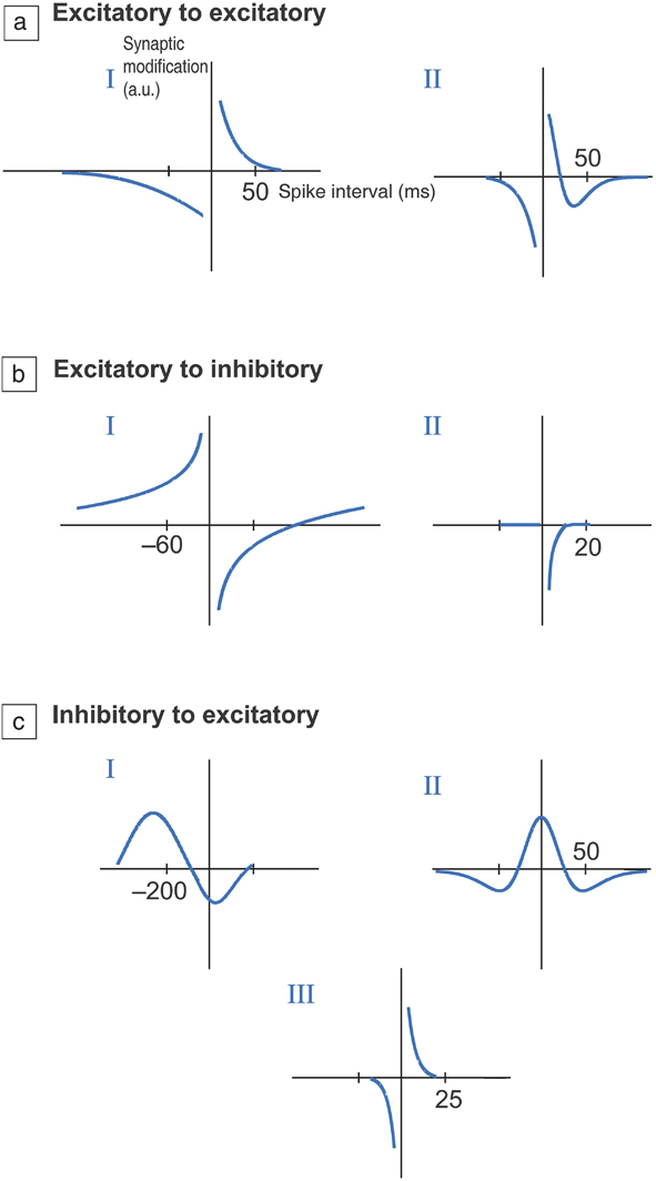
Synapses connect neurons, and each neuron may possess anywhere from a handful to several hundreds of synaptic connections. Synapses play an important role in information processing and learning. They can modify their electrical resistance based on past stimuli and interactions with their local environment, and dynamically adjust their resistance based on action potential profiles and time intervals. The modification of the resistance of synapses based on time delays between action potentials is referred to as synaptic plasticity and is one of the principal mechanisms by which an organism can continuously learn from its environment. Plasticity is also considered to be one mechanism for individuality among living beings. Figure 3 shows different types of adaptive behavior exhibited by synapses.Reference Caporale and Dan9 The plots schematically illustrate the change in conductance (y-axis) of a synapse depending on the time interval (x-axis) between neuron firings. Depending on the magnitude and order of pulses received from two inputs, the resistance of a synapse may change accordingly. In certain cases, the plasticity, defined by the change in resistance, may only depend on the time interval between spiking events and not on the sequence of pre- versus postsynaptic terminal activity. Poo et al. experimentally measured synaptic behavior in a rat brain, and one representative data set is shown in Figure 4.Reference Dan and Poo10 The change in synaptic resistance is represented by the y-axis normalized excitatory postsynaptic potential, while the x-axis corresponds to the time interval between neuron spikes adjoining a synapse. As can be seen, the synaptic resistance change increases as the time difference between spikes become smaller. This is one form of spike timing dependent plasticity (STDP). As the time interval becomes much larger than 100 ms, the change in resistance becomes negligible, suggesting the firing events are uncorrelated. The sign of resistance change that corresponds to strengthening or weakening of the synapse depends on which spiking event occurs first, the pre- or postsynaptic terminal. Reproducing such STDP in physical analogs is a major research activity,Reference Jeong, Kim, Ziegler and Kohlstedt11 and is also actively investigated in machine intelligence and algorithm development for neural networks.Reference Tsodyks, Pawelzik and Markram12 This forms one foundational aspect of incorporating intelligence and memory in artificial circuits using temporal correlations of signals.
Different types of temporal windows for synaptic plasticity. (a) Excitatory to excitatory connection, (b) excitatory to inhibitory connection, and (c) inhibitory to excitatory connections. Excitatory connections increase the probability of an action potential occurring in a postsynaptic neuron, while inhibitory synapses decrease the probability. The vertical axis represents change in resistance of the synapse (in arbitrary units) as a function of time interval between firing of neurons at the pre- and postsynaptic terminals. This adaptive change in resistance due to neuron activity history is referred to as plasticity and is central to learning. I, II, and III refer to distinct types of plasticity that are observed within each set of connection types and can vary depending on the neural circuit pathway or organism being studied. In most cases, if the time interval is short, typically on the order of tens of milliseconds, then the resistance change is maximal. If the neurons fire after much longer time scales, then change in resistance approaches zero as the firing events are not correlated; therefore, there is no plasticity. Essentially, plasticity versus time delay can display several functional relationships, depending on the organism as well as the neural network. This has significant ramifications in adaptive materials design to mimic synapses. The time axis is in milliseconds. Reprinted with permission from Reference Reference Caporale and Dan9. © 2008 Annual Review of Neuroscience.
Synaptic modification induced by paired pre- and postsynaptic spikes in cortical slices from a rat. Change in resistance of a synapse due to neuron activity is plotted as a function of time interval between spikes. The pre- and post- neurons are shown as firing at different times represented by the action potential spikes (i.e., vertical lines in the inset). The horizontal dashed lines represent the orthogonal axes corresponding to time interval between neuron firing (x-axis) and percent change in synaptic potential (y-axis). The solid lines are fits to the data. Depending on which (i.e., pre- or post-) neuron fires first, the synaptic strength can be reduced (depression, corresponding to post–pre) or strengthened (potentiation, corresponding to pre-post). As the time interval between neuronal firing shrinks, the synaptic modification increases. Whereas if the time interval is large, there is no modification of the synapse. The resistance change (or plasticity) can vary in sign depending on the order of spiking events across the junction, and is referred to as potentiation or depression as previously noted. Hence, the synapse represents a unique kind of resistor that is both tunable and history dependent. The resulting plasticity exhibited in the brain inspires discovery and emulation of synaptic behavior in synthetic matter. Note: EPSP, excitatory postsynaptic potential. Reprinted with permission from Reference Reference Dan and Poo10. © 2006 American Physiological Society.

At the individual neuron or synapse level, basic characteristics concerning signal propagation are beginning to be understood. How they are interconnected to form circuits and process specific kinds of information is clearly a much more complex problem. For instance, the human brain comprises billions of neurons and trillions of synaptic connections.Reference Sejnowski and Delbruck13 Hence, collective behavior at various connection densities emerge and contribute to unique cognitive capabilities mediated by plasticity (reminiscent of “more is different” by AndersonReference Anderson14). What capabilities arise in an organism when certain minimal numbers of neurons or neuronal densities are present in the brain is therefore of great significance in the understanding of origins and evolution of intelligence and cognitive skills. This is also intimately related to learning and decision making, memory formation, episodic memory, and spatiotemporal dynamics in foraging and mating strategies in animals.Reference Griffiths, Dickinson and Clayton15 At an even higher level, collective behavior and intelligence manifests at the colony scale, where examples include cooperative feeding in bottlenose dolphins and pattern formation in bird flights. While this is related to the elementary capabilities at the neuronal level, we do not discuss it further in this article. Such studies form a significant part of evolutionary biology and inspire new machine learning algorithms, examples include swarm intelligenceReference Yang, Cui, Xiao, Gandomi and Karamanoglu16 and learning by forgetting.Reference Panda, Allred, Ramanathan and Roy17
Artificial neurons with quantum materials
The principal function of a neuron is to generate action potentials that are transmitted to other parts of the nervous system, as noted in the previous section. Insulating sheaths surrounding the neuron ensure that the signal does not leak into adjacent regions. Elementary mechanisms leading to the generation of action potentials in the biological neuron are related to chemical gradients across membranes coupled with selective ionic transport (e.g., Na+, K+) via voltage-gated permeation channels.Reference Catterall18 The quest to realize artificial neurons has so far been primarily related to efforts in brain-inspired computing. In this context, it is worth noting that materials scientists are mainly attempting to mimic the function of the neuron as opposed to their exact shape, appearance, rigidity, or form. Hence, both ionic and electronic currents that can generate action potentials are of interest. Quantum materials are particularly relevant in this context, due to their highly nonlinear properties and tunable fragile electronic structure.
Figure 5 shows an example of artificial spiking neurons built with a phase-changing oxide, VO2.Reference Lin, Sonde, Chen, Stan, Achari, Ramanathan and Guha19 Self-sustained voltage oscillations appear when a tunable resistor is connected with a capacitor, thereby greatly simplifying neuron design. On the other hand, to realize similar spiking behavior with traditional complementary metal oxide semiconductor (CMOS) circuits might require more than 10 transistors. Similar circuits can be designed with a plethora of other correlated materials that undergo electrically driven insulator–metal transitions such as lacunar spinel compounds and NbO2.Reference Stoliar, Tranchant, Corraze, Janod, Besland, Tesler, Rozenberg and Cario20–Reference Gao, Chen and Yu22 In fact, relaxation oscillations in NbO2 were observed more than 35 years ago, indicating long-standing interest in the unique electronic behavior of phase switches.Reference Lalevic and Shoga23 Such a device can integrate charge and fire at a threshold voltage that directly mimics a biological neuron. By careful choice of the correlated insulator and optimization of the geometry and ground-state conductivity with defects, it is possible to tune the critical voltages needed for firing. This area forms a significant portion of brain-inspired electronics research. In addition to phase transitions, spin torques in magnetic layers can also be exploited to mimic neurons and contributes to ongoing interest in spintronics.Reference Locatelli, Cros and Grollier24
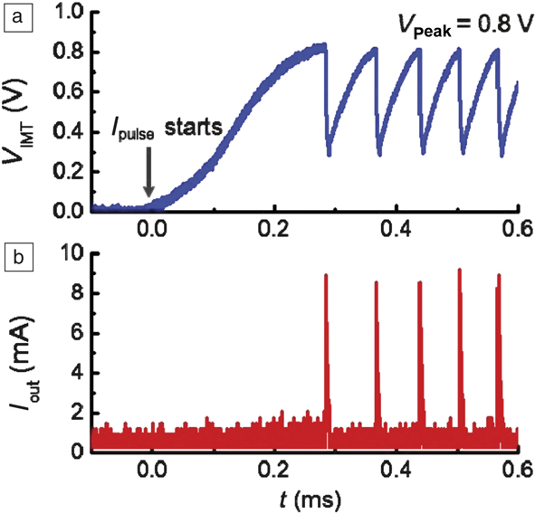
Spiking neurons designed with phase-changing VO2 devices. (a) The insulator–metal transition occurs at 0.8 V in the VO2 artificial neuron device. Once the transition happens, the voltage drops rapidly due to its conducting nature. The voltage then gradually rises again as the VO2 recovers to the original state. The process is repeated as the neuron fires when the next phase-change occurs. (b) Spikes in current output corresponding to the material undergoing a phase change. The threshold voltage can be adjusted by controlling the electrical resistivity of the switching material via defects. Note: V IMT, voltage across the phase-changing switch; I pulse initial current supplied to the circuit; I out current pulse fired by the artificial neuron. The horizontal axis represents time, denoted by t, in units of milliseconds. The time lag between initial application of the current pulse to the current output that is seen as a spike in (b) represents an integration period where charge is collected. The neuron oscillation period can be tuned by controlling thermal dissipation.Reference Lin, Sonde, Chen, Stan, Achari, Ramanathan and Guha19
Artificial synapses with quantum materials
Unlike the limited demonstrations of synthetic neurons, a great many materials have been used to design artificial synapses, where these build on history-dependent or programmable resistance states. Examples include wide-band insulating oxides with filamentary defects, ferroelectrics, tunnel junctions, and organic systems.Reference Jeong, Kim, Ziegler and Kohlstedt11,Reference Locatelli, Cros and Grollier24–Reference Burgt, Lubberman, Fuller, Keene, Faria, Agarwal, Marinella, Talin and Salleo26 Collective quantum effects are of interest for designing synapses owing to the homogenous resistance modification that is possible by either changing orbital occupancy or creating defects that can modify the insulating state conduction mechanism. Consequently, both two- and three-terminal devices can be designed. Two-terminal devices offer the simplicity of fabrication using metal electrodes that sandwich a tunable electronic or ionic resistor medium. Combined with Schottky junctions, they can be integrated into crossbar geometries to realize memory device architectures. Three-terminal devices are similar to a field-effect transistor wherein the switching medium is separated from the metal electrode by an insulating layer. In the latter case, an electric field applied to the gate can cause ionic displacement into the channel and mediate the conductance. In both cases, quantum materials offer unique opportunities: room temperature operation and compatibility with integration onto existing integrated circuit platforms.
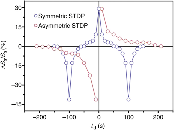
Figure 6 shows synaptic plasticity realized in a correlated perovskite nickelate transistor with ionic liquid gates.Reference Shi, Ha, Zhou, Schoofs and Ramanathan27 In this case, the ionic liquid is used as a local reservoir for oxygen that can be extracted from the nickelate leading to nonvolatile change in resistance. The oxygen can be reinserted by applying a gate voltage of the opposite polarity, making the process reversible. The devices show potentiation (depression) behavior as voltage pulse trains can sequentially modify the resistance of the channel due to creation of greater (lower) concentration of defects. It is of utmost importance to understand the elementary mechanisms leading to the resistance changes. Typical oxygen vacancy defects in insulating oxides such as TiO2 lead to an increase in conductivity by donating electrons to the conduction band per the defect reaction written in Kröger–Vink notation:Reference Nowotny, Bak and Nowotny28–Reference Tuller and Bishop30
 $$O_O^X \to {1 \over 2}O_2 + V_{\rm{\"o }} + 2e^{\rm{-}} .$$
Asymmetric and symmetric spike timing dependent plasticity (STDP) demonstration using a perovskite nickelate transistor. An ionic liquid gate is used to sustain an electric field and simultaneously serve as a reservoir for oxygen that can be readily exchanged with the lattice. Note: S s, conductance of the nickelate channel; ΔS s, change in the conductance upon application of a voltage bias to the gate; t d, time delay between voltage pulse applications in units of seconds. Qualitative comparison with the schematics in Figure 3 shows how different forms of biological plasticity can be directly mimicked with an artificial three-terminal synapse fabricated from a quantum material.Reference Shi, Ha, Zhou, Schoofs and Ramanathan27
Here,  $O_O^X$ refers to oxygen in the lattice located at an oxygen site (O) with neutral charge (x), and ${V_{\rm{\"o }}}$ refers to a vacancy in the oxygen sublattice leading to a double positively charged defect that is compensated by two electrons. However, in certain oxides, depending on the position of the oxygen versus cation bands, the electrons can be transferred to the cation site, leading to localization. Specifically, in the case of nickelates, the nominal Ni site valence can be modified according to the following defect reaction:
 $$O_O^x + 2Ni^{3 + } \to {1 \over 2}O_2 + V_{\rm{\"o }} + 2Ni^{2 + } .$$
Here, Ni3+ refers to the valence of Ni in the nickel site, which is modified by the anchoring of electrons. The electrons from O vacancies are transferred to the e g orbital in Ni, leading to half-filling and consequently, a large increase in resistance.Reference Ramadoss, Mandal, Dai, Wan, Zhou, Rokhinson, Chen, Hu and Ramanathan31,Reference Nikulin, Novojilov, Kaul, Mudretsova and Kondrashov32 In fact, this is the exact opposite of what happens in VO2 when oxygen vacancies are introduced, the reduction of valence from V4+ to V3+ increases the electronic conductivity. Hence, depending on where the electrons are transferred, the conductivity can be modulated. Synaptic plasticity has also been demonstrated by electron doping from the gas phase using hydrogen.Reference Zuo, Panda, Kotiuga, Li, Kang, Mazzoli, Zhou, Barbour, Wilkins, Narayanan, Cherukara, Zhang, Sankaranarayanan, Comin, Rabe, Roy and Ramanathan33 The hydrogen splits into a proton and electron at the vicinity of a catalytic electrode, and the electron anchors to the Ni orbitals, leading to resistance change.
AI networks using quantum materials
Integrated devices and circuit demonstrations using quantum materials are still at the nascent stage. However, proof-of-concept networks have been demonstrated. Figure 7 shows an example of ionic liquid gated nickelate synapses incorporated into a classical conditioning circuit.Reference Ha, Shi, Meroz, Mahadevan and Ramanathan34 Classical conditioning can be described as an associative learning process wherein a stimulus that is initially neutral can be taught to trigger a response after sufficient activation. Such circuits can be used to experimentally emulate animal learning behaviors, such as, but not limited to, the well-known Pavlov dog experiment. Here, an initially neutral stimulus (sound of a ringing bell) can eventually be associated with food by synchronizing the two events. NbO2 neuron-based pattern recognition networks for recognizing integers have recently been demonstrated.Reference Moon, Cha, Park, Gi, Chu, Baek, Lee, Oh and Hwang35 The time-dependent evolution of electrical behavior can be incorporated into standalone algorithms for neuromorphic networks by augmenting STDP models. Interest in machine learning therefore opens up previously unexplored territory for exotic materials—to serve as inspiration for new electronic plasticity models that can be directly incorporated into neuromorphic network simulations.
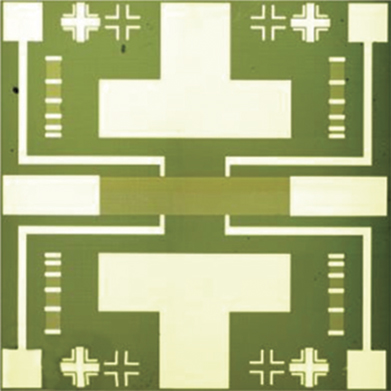
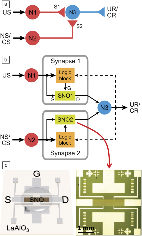
(a) Schematic of a neural classical conditioning circuit incorporating strongly correlated synapses. Circles represent neurons (N1, N2, N3) and triangles represent synapse connections (S1, S2) and neuron outputs. (b) Schematic of an electronic classical conditioning-unlearning circuit. US, UR, NS, and CS represent unconditioned stimulus, unconditioned response, neutral stimulus, and conditioned stimulus, respectively. SNO1 and SNO2 represent two synaptic devices incorporated into the circuit fabricated with the perovskite semiconductor SmNiO3 (SNO). The dashed line represents a back-propagating signal from N3 that correlates with signals from N1 and N2. The stimulus is received or transmitted through neurons N1 and N2 while N3 outputs the response. The logic block sends signals to the synapse corresponding to an increase or decrease in resistance (potentiation or depression, respectively) depending on the time interval between neuron spiking. US and NS (or CS) signals transmit through the two nickelate synapses SNO1 and SNO2, respectively, to neuron N3. (c) (Left) Illustration and (right) optical micrograph of a three-terminal synaptic device. Illustration shows ionic liquid (IL) interfacing with the SNO channel along with source (S), drain (D), and gate (G) electrode labels. The synaptic device can display plasticity behavior similar to that shown in Figure 6. The resistance of the nickelate synapses therefore will determine whether N1 and N2 can fire and correspondingly will affect the voltage output at N3.Reference Ha, Shi, Meroz, Mahadevan and Ramanathan34
Future outlook on multidisciplinary research
The possibility of reconfigurable band structure by doping, induced stress from external stimuli, and the chemical environment presents a multitude of opportunities. State changes can be homogenous and not limited by screening length. An important attribute of quantum materials is the controllable binding of dopants to the lattice. If the dynamics of relaxation can be controlled, then decay of memory states can be programmed. This would be a key enabler for machine learning, as memory constraints are ubiquitous in AI systems that are similar to the animal brain. Retention of important information can be prioritized over noncritical information, in a similar way to how humans process information and store memories for lifelong learning.Reference Kirkpatrick, Pascanu, Rabinowitz, Veness, Desjardins, Rusu, Milan, Quan, Ramalho, Grabska-Barwinska and Hassabis36 In the future, such systems may be helpful to model diseases such as Alzheimer’s, where critical information is forgotten. Much work to date in artificial neurons and synapses has been oriented toward building hardware components for brain-inspired computing. This is but one of the research opportunities presented by quantum materials. As with the increasing use of organoidsReference Lancaster, Renner, Martin, Wenzel, Bicknell, Hurles, Homfray, Penninger, Jackson and Knoblich37 to understand properties and behavior of organs ex vivo, we can, in synthetic neuroscience, think of designing circuits for use as model systems to simulate features of a brain, thus complementing experiments on animals in neuroscience. This is, however, not a trivial task due to the large numbers and as yet undiscovered nature of neural connections. Nevertheless, one may think of model organisms that have been studied in neuroscience such as the roundworm C. elegans, which has 302 neurons.Reference Rankin, Beck and Chiba38
Artificial neural circuits comprising adaptive matter require much research from a microscopic perspective. The connections among orbital overlap, strain, and nature of the ground state are of central importance.Reference Rondinelli, May and Freeland39 Since the dopant density required to modulate carrier density is quite high (approaching a fraction of a carrier per unit cell), the impact on the lattice in terms of strain, bond-angle distortions, and crystal symmetry changes become important. Such problems couple well to both ab initio and molecular dynamics simulation studies. Very little is known about the thermodynamics of defect states within the gap and how charged dopants affect orbital filling and magnetic order. In situ and in operando techniques with synchrotron spectroscopy on epitaxial films are increasingly being exploited to understand basic aspects of the electronic structure modification processReference Leng, Pereiro, Strle, Dubuis, Bollinger, Gozar, Wu, Litombe, Panagopoulos, Pavuna and Božović40 and will likely be a centerpiece of research in this area, especially as new diagnostic capabilities such as high-pressure x-ray spectroscopy, nanoscale probes, and ultrafast photon spectroscopy tools become widely available for materials characterization. Advancing fundamental knowledge to control and direct atomic-scale pathways for phase change in quantum materials can open up discovery of metastable states of matter with unique electromagnetic properties that are as yet unknown.
Acknowledgments
S.R. acknowledges ARO W911NF-16–1-0289 and AFOSR FA9550–16–1-0159 for support and Z. Zhang for reading of the manuscript and assistance with figures.

Shriram Ramanathan is a professor of materials and electrical and computer engineering at Purdue University. He received his PhD degree from Stanford University in 2002. He was a member of the research staff at Components Research, Intel, for more than three years. He served on the applied physics faculty at Harvard University for nearly a decade. Ramanathan can be reached by email at shriram@purdue.edu.


