

1. Introduction
The demand for tasks beyond the confinements of a work cell requires the use of mobile robots. This has seen the development of various kinds of mobile robots at an unprecedented pace for operations in air, land, and water. Applications for such robots include oil and gas refinery inspection [Reference Hutter1], underwater mapping [Reference Nancekievill2, Reference Palomeras, Nagappa, Ribas, Gracias and Carreras3], radiation mapping [Reference Li, Zhu, Wang, Li, Peng and Ge4, Reference Connor5], and nuclear decommissioning [Reference Bird6, Reference West7].
The primary limitation for the deployment of mobile robots for an extended period of time is its limited onboard battery capacity. While technological advances have increased the energy capacity and power output of batteries, this capacity is still lacking for robots. Limited by this, the options for mobile robots are to either return to a base station for charging, have its battery replaced manually, or operate with a tether. The first two options result in downtime for the robot while the third option presents additional challenges such as tether crossovers, limited bending around obstacles, reduce in the robot payload from the tether system, all of which limit the mobility and performance of the robot [Reference West8].
A possible solution to the limited capacity of batteries is the use of wireless power transfer (WPT) technologies to provide power alongside, or replace, the robot's onboard battery. This solution has the potential to address the energy requirement of the robot without compromising on both the robot's operational time and mobility associated with the options present above. Other potential advantages include higher power transmission efficiency (PTE), elimination of spark from contacts [Reference Park, Lee, Cho, Choi and Rim9], and redundancy for tether.
The WPT literature is primarily focused on either high-power (kW) applications such as electric vehicles, which typically operate with transmission distance of <0.3 m [Reference Choi10] or low-power (less than a few Watts) applications such as consumer devices at centimeter distances, wireless sensor network (WSN) at kilometer distances [Reference Xie, Shi, Hou and Lou11] and medical implants at centimeter distances [Reference Kim, Hirayama, Kim, Han, Zhang and Choi12]. However, the use of WPT for the mobile robots in this study requires mid power ( $\sim 100\,{\rm W}$) and transmission distances of 1–20 m.
The primary challenge of WPT here is to deliver the power required to a non-stationary mobile robot without compromising the robot's mobility and its mission. This is compounded by additional challenges such as system efficiency, the device form factor (size, mass, ancillary components), transmission distance, and medium. An additional consideration is human safety in scenarios where human and robots work in the same environment.
The contribution of this study is to collate the state-of-the-art in WPT and analyze the applicability of such technologies for mobile robots. In particular, the challenges of a WPT system detailed above will be considered in detail for mobile robots. The mobile robots selected for the case study in this research are a representation of the robots available in the literature targeted for deployment in a hazardous environment. However, the outcome of this research is applicable to mobile robots in general.
The rest of this paper is structured as follows: Section II presents the problem statement for this work, detailing the scenarios and case study robots. Section III presents an overview of WPT technology and recent work on WPT for mobile robots. Section IV details the analysis of WPT technologies for the scenarios considered in this study. Section V discusses the results of the analysis and its applicability for the robots considered in this study. Finally, Section VI summarizes the work and sets the outlook to the future.
2. Problem Statement
The problem statement on the use of WPT for mobile robots may be formulated by first identifying the environments where mobile robots are used, followed by the type of mobile robot used, and finally the power transfer scenarios of concern in this study.
2.1. Deployment scenarios
Advances in technology have led to mobile robots being considered for deployment in environments which are hazardous to humans to perform remote inspections and interventions. Such environments include, but are not limited to, nuclear plants, offshore wind turbines, oil and gas platforms, offshore substations, underground mining tunnels, and underwater pipes. These environments dictate the type of medium that the robot has to operate in, typically either air or water.
Due to the hazardous nature of these environments, transmitting power directly to these robots may not be possible and needs to pass through different mediums. For example, a robot deployed in a sealed room, common in nuclear facilities, will require power transmission through reinforced concrete or lead glass. Robots deployed for in-pipe inspection will require power transmission through metal or plastic, while underwater robots may require power transmission through the containing vessel which could be made of concrete or metal. The type of medium for power transmission is thus broadly categorized as air, optically translucent (water and glass) and optically opaque (concrete, reinforced concrete, and metal).
2.2. Mobile platforms
This section presents the state-of-the-art mobile robot which represents the generic robot types for ground, aerial, and underwater targeted for deployment in hazardous environments. Figure 1 shows the robots considered in this study, while the parameters on the robot's power and battery requirements are summarized in Table 1.

Fig. 1. (a) Husky [Reference West8], (b) ANYmal [Reference Hutter1], (c) CARMA 2 [Reference Bird6], (d) Corin [Reference Cheah, Khalili, Arvin, Watson, Lennox and Green13], (e) Phantom Pro 4, (f) Matrice 600 Pro, (g) AVEXIS [Reference Nancekievill2], (h) BlueROV.
Table 1. Robot parameters considered in this study.

* Values inferred from datasheet or communication with authors.
Both wheel and legged robots of medium (ANYmal and Husky) and small (Jackal and Corin) scale have been included for ground-based robots as these platforms have gained significant interest in the industry and research community due to their availability or capability that previous platforms have not been capable of achieving [Reference West8, Reference Tong, Gingras, Larose, Barfoot and Dupuis14, Reference Leigh, Pineau, Olmedo and Zhang15]. The AVEXIS and BlueROV represent the mini- and small autonomous underwater vehicle (AUV) scale robot which is more suitable for the hazardous environment [Reference Watson16].
The two unmanned aerial vehicles (UAVs) selected here represent the medium and large class for UAVs available in the market. Medium size UAVs, such as the Phantom 4Footnote 1, are typically used with their onboard camera only with no reported payload capability. The camera itself is sufficient to be used for remote inspection and characterization [Reference Connor5, Reference Boudergui17]. The Matrice 600 ProFootnote 2 represents the large class of UAV with payload capability. This allows different sensors or manipulators to be mounted to it, allowing for a larger array of tasks to be undertaken [Reference Li, Zhu, Wang, Li, Peng and Ge4, Reference Suarez, Jimenez-Cano, Vega, Heredia, Rodriguez-Castaño and Ollero18, Reference Beachly, Detweiler, Elbaum, Twidwell and Duncan19].
2.3. Power transfer scenarios
There are three different WPT scenarios for the robot:
1) Net increase: The power consumption of the robot, P c, is less than the power received, P R. In this case, prolonged power transfer will lead to a fully charged battery. The robot may be in either operational or standby mode, the latter in which the robot is stationary with negligible P c.
2) Zero net: The difference between the net power consumption and power received is zero (P c = P R), hence the energy of the battery remains constant.
3) Net decrease: The power consumption is higher than the power received, P c < P R. In this scenario, the battery energy will eventually reach zero.
The first and second scenarios are preferred as these ensure that the onboard battery is not depleted. A smaller battery pack may be used on the robot in both these scenarios, allowing the robot's payload to be increased. This study will consider the second scenario in increasing the robot's operational time. Therefore the required output power of the WPT corresponds to the Power consumption column in Table 1.
An important factor in WPT is the transmission distance, d, achievable for a desired power output. The following definitions for transmission distance are used in this study as they are more relevant to the applications:
1) Very short-range: d < 0.1 m
2) Short-range: 0.1 m ≤ d ≤ 1 m
3) Mid-range: 1 m ≤ d ≤ 5 m
4) Far-range: 5 m<d ≤ 20 m
5) Very far-range: >20 m
The problem statement can thus be stated as the feasibility of a WPT technology for delivering the power required through different transmission mediums for a non-stationary mobile robot operating within mid- to far-range distances. The form factor (size and mass) of the WPT system should also be within payload capability of the mobile robot. This research focuses on end-to-end WPT system only, i.e. the power is transmitted directly to the receiver on the robot without requiring relay systems, whether stationary set up or mobile robots.
3. Related Work
This section reviews the available technologies for WPT and its application in mobile robots. For each technology, a brief description of the underlying principles is first presented followed by its application. For a more comprehensive review on the respective technologies, the interested readers are referred to [Reference Lu, Bagheri, James and Phung20–Reference Roes, Duarte, Hendrix and Lomonova23].
WPT can be broadly categorized as radiative and non-radiative as shown in Fig. 2. The two techniques in the literature using radiative power transfer are microwave power transfer (MWPT) and laser power transfer (LPT). Non-radiative power transfer technologies are inductive power transfer (IPT), magnetic resonance power transfer (MRPT), capacitive power transfer (CPT), and acoustic power transfer (APT). Each technology can be further categorized into direct or background energy harvesting. The difference between these two is that the former receives energy from a source that has been set up with the purpose of transmitting power to the receiver. On the other hand, the latter harvest background energy that is a by-product of another process and not targeted for powering devices, such as heat from a coolant system and radio waves from wireless communication [Reference Chen24, Reference Shinohara25].
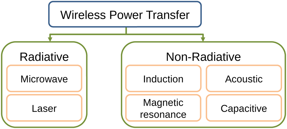
Fig. 2. Wireless power transfer technology classification.
Table 2 summarizes the main characteristics of the different types of technologies. Of interest are the system efficiency, transmission distance, the ratio between transmission distance and receiver diameter, R tr, maximum power transferred, and the hazardous potential of these technologies.
Table 2. Summary of the different WPT in air.

3.1. APT
This technology utilizes sound for power transfer, typically in the megahertz range (0.5–2.25 MHz) [Reference Roes, Duarte, Hendrix and Lomonova23]. A transducer converts electrical power to mechanical power by vibrating the active area. The medium which the transducer is connected to, such as air or wall, then resonates and propagates the vibration through the entire medium. The propagated vibration that reaches the receiver is then converted back from mechanical to electrical power. This methodology is illustrated in Fig. 3.

Fig. 3. Basic methodology of AET technology [Reference Awal, Jusoh, Sabapathy, Kamarudin and Rahim39].
Application for this technology is primarily in low-power biomedical implant devices (mW) [Reference Zaid, Saat and Yusmarnita Yusop40]. Medium- and high-power transfer of 62 W and 1 kW has been achieved although at non-air, small transmission distance of 70 and 5 mm, respectively [Reference Leung, Willis and Hu41, Reference Bao42]. These are targeted toward sealed environments such as containers with hazardous objects [Reference Bao42]. The maximum efficiency achieved for transmission in the air was 4% at 0.045 m transmission distance [Reference Tseng, Bedair and Lazarus26]. Although the efficiency was lower compared to IPT at 0.045 m, the efficiency trails off slower compared to IPT (2% for APT compared to 0% for IPT at 0.12 m). To the author's best knowledge, this technology has not been used for powering mobile robots.
3.2. CPT
The idea behind this technology is to separate the pair of capacitor plates so that one acts as a transmitter, while the other acts as the receiver. CPT is different in that it uses electric instead of magnetic field for transferring power. The coupling capacitance is defined by
 $$C = \displaystyle{{k\ε _oA} \over d},$$
where ε o = 8.85 × 10⁻¹² F/m is the permittivity of space, k is the relative permittivity of dielectric between material, A is the surface overlap between the plates, and d is the separation distance between the plates. Evidently, the coupling capacitance is small due to ε o, thus requiring large metal plates and high voltage resonance operation for power transfer at larger distances.
This technology has been used on mobile robots as well besides electric car charging [Reference Lu, Zhang, Hofmann and Mi27, Reference Lu, Zhang, Hofmann and Mi43]. In [Reference Hu, Liu and Li44], mobile soccer robots have been equipped with parallel capacitor plates for docking-station type wireless charging. The proposed system has a form factor of 0.03 × 0.09 m2 and achieved 44.3% efficiency. In [Reference Mostafa, Muharam and Hattori45], a stationary UAV was charged using CPT where the entire landing pad acts as the transmitter. Their approach minimizes the need for accurate alignment and achieved 50% efficiency for 12 W power output. A similar approach was used in [Reference Muharam, Mostafa and Hattori46] with improvements on the ancillary system, achieving a higher efficiency of 77% although at only 8 W of power output. Common to these mobile robots applications for CPT are the small transmission distance, typically in millimeter distances.
3.3. IPT
This technology relies on inductive coupling, which is achieved by the electromagnetic induction between a primary and secondary coil. An AC current passing through the primary coil generates a magnetic field which then induces voltage across a secondary coil. An example of such a system is the power transformer where there are no direct connections between the primary and secondary coil. The magnetic field, B, at any point in space, d, created by the primary coil is defined by the Biot–Savart's Law as
 $$B\lpar d \rpar = \displaystyle{{\mu _o} \over {4\pi}} \int_C {\displaystyle{{Id_I \times d} \over {\vert {d^3} \vert }}}, $$
where μ o is the permittivity of free-space and I is the current through the conductor at section d I. As seen from this relationship, the magnetic field is inversely proportional to distance, B ∝ 1/d 3, causing the power transfer to drop significantly over larger distances.
The use of this technology is considered matured and has been used in short-range consumer products such as wireless toothbrush, medical implants, and cellphones [Reference Kim, Hirayama, Kim, Han, Zhang and Choi12]. Application of this technique to mobile robots is limited to situations where the robot is within close proximity to the transmitter. The use of a power floor mat allows for a large charging area for single- [Reference Park, Lee, Cho, Choi and Rim9] and multi-robot scenarios [Reference Chen, Tong, Meyer, Abdolkhani and Hu47, Reference Arvin, Watson, Turgut, Espinosa, Krajník and Lennox48]. In [Reference Park, Lee, Cho, Choi and Rim9], the entire mat consists of only a single-layer transmitter coil and multiple pickups were used on the receiver to achieve more regular power output across the mat.
In [Reference Chen, Tong, Meyer, Abdolkhani and Hu47], the coils on the transmitter mat have been designed for higher power distribution at a fixed diameter so that similar power can be transferred to multiple robots. In [Reference Arvin, Watson, Turgut, Espinosa, Krajník and Lennox48], multiple transmitter coils were arranged in a grid to achieve large coverage and dynamic charging in an arena. For underwater robots, guide, and locking mechanisms have been used to align the coils, arranged in an outer (transmitter) and inner (receiver) loop, and to hold the robot in place [Reference Shi, Li and Yang49–Reference Lin, Li, Zhang and Lin51].
3.4. MRPT
This technology is considered a special case of IPT whereby strong electromagnetic coupling is achieved by operating at the resonance frequency of the coils. This principle of operation can be achieved using two (similar to inductive coupling) or more coils (see Fig. 4) [Reference Zhong, Zhang, Liu and Hui52, Reference Kurs53], where having more intermediary coils increases the transmission distance. There are two principles of operation, namely power delivered to load (PDL) and PTE [Reference Hui, Zhong and Lee54], where a trade-off on either the power delivered or the system efficiency is observed.
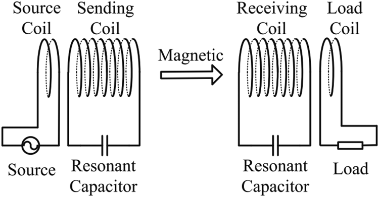
Fig. 4. Schematic representation of magnetic resonance coupling technology [Reference Zhang55].
The transmission efficiency for MRPT follows a similar trend to IPT where it trails off with 1/d 3. High system efficiency is achieved by selecting high-performance subsystems such as the power supply [Reference Liu, Liu, Yang, Ma and Zhu56], coil configuration [Reference Kiani, Jow and Ghovanloo57], and coil material [Reference Sun58]. Due to the coupling effect, the power transfer does not follow the transmission efficiency curve. The coils may be wound around a ferrite core to increase the mutual coupling [Reference Kürschner, Rathge and Jumar59] or air core for compact and lightweight design although at the expense of lower coupling [Reference Kurs53, Reference Sample, Meyer and Smith60].
While a large body of research in this technology is focused toward electric vehicles [Reference Mi, Buja, Choi and Rim61], this technology has also been used on mobile robots operating in air, ground, and underwater. In [Reference Yamakawa, Shimamura, Komurasaki and Koizumi62], a four-coil MRPT system was used to power a small electric helicopter with automated impedance matching for improved transmission efficiency. In [Reference Campi, Cruciani and Feliziani63], the receiver coil was wound around the UAV's landing leg to keep the central area clear for application-specific purposes. In [Reference Han, Chau, Jiang, Liu and Lam64], a 3D receiver coil was proposed to address the alignment requirement. This set up allows a single transmitter coil to be used while still achieving high efficiency compared to multiple transmitters. Besides being used for powering the robot, the feasibility of charging sensor nodes from a UAV was shown in [Reference Griffin and Detweiler65].
On ground, a docking station setup is used for charging Team Air-K's robot in the ARGOS challenge and the Docent robot through a wall [Reference Cho, Kim, Moon, Yoon, Jeon and Choi66]. In [Reference Liu67], underground guide rails along the navigation path allow robots traveling along these paths to be charged dynamically [Reference Liu67]. Underwater power transfer using MRPT has been proposed for an AUV [Reference Pereira, Santos, Pessoa and Salgado68], showing the effects of underwater transmission compared to air for circular and spiral coils. However, the proposed system has not been evaluated on an actual platform.
3.5. MWPT
Microwave is used as the medium for transmitting energy in this radiative technique. The underlying technology for this technique is similar to wireless communication using radio frequency (RF). Electrical energy converted into microwaves at the transmitter end is transmitted either in an isotropic or beam-forming manner. The former is commonly used in communications and in WSN which allows a larger area coverage for simultaneous wireless information power transfer applications while the latter is typically used for transmitting to a single point, such as solar power satellites. The receiver then converts the microwave received back into electrical energy.
The potential damaging effect from exposure to high-power microwave radiation limits the application of this technology, where living tissues exist, to low-power applications with the safety regulation set at 1 mW/cm2 [Reference Foster69]. Hence sensors in WSN are typically low powered (<1 W) while high-power base station (>1 GW) is out of bounds for human entry. The high-power density transmission for both short and far-range distance has been demonstrated before the turn of the century [Reference Brown70]. However, the transmission area is a human-free zone and the antennas are typically large and immobile.
Applications of MWPT for mobile robots include micro UAV with mW power requirements [Reference Shimamura71], proof-of-concept mini airship at 0.83 W [Reference Kim, Yang, Song, Jones, Elliott and Choi72], a charging mat area for ground robots [Reference Okuyama, Noda and Shinoda73], a low-power 4 W rover [Reference Kawasaki74], and for pipe inspection robot [Reference Sato, Shinohara and Jodoi75]. To adhere with safety regulation, the power transmitted was either kept low [Reference Shimamura71], thus limiting the power output, or required the use of waveguide to contain the radiation [Reference Okuyama, Noda and Shinoda73, Reference Sato, Shinohara and Jodoi75].
3.6. LPT
This technique uses radiative electromagnetic field, similar to MWPT, except that the wavelengths used are near the visible or infrared spectrum. Figure 5 shows the schematic representation of an LPT system. The transducer produces a highly collimated beam (beam director) which the receiver, termed as laser power converters (LPC), then converts back to electrical power. The use of solar panels for the conversion was used in early works but this was inefficient as solar panels were designed to operate over a large spectrum while laser beams are monochromatic. Higher efficiency has been achieved by designing monochromatic-photovoltaic cells for a specific wavelength [Reference Bett, Dimroth, Lockenhoff, Oliva and Schubert76]. The short wavelength used for LPT allows for longer transmission distance but factors such as moisture and dust particles in the transmission medium will attenuate the transmission efficiency [Reference Sahai and Graham77].

Fig. 5. Schematic diagram of LPT technology [Reference Jin and Zhou78].
Applications for LPT have been demonstrated for very far-range transmission on a smartphone [Reference Iyer, Bayati, Nandakumar and Majumdar79] and UAVs with varying sizes [Reference James, Iyer, Chukewad, Gollakota and Fuller80, Reference Achtelik, Stumpf, Gurdan and Doth81]. In [Reference James, Iyer, Chukewad, Gollakota and Fuller80], commercially available components were used for the LPT system to achieve around 0.3 W power output at 1 m. In [Reference Achtelik, Stumpf, Gurdan and Doth81], the power delivered was sufficient for a 1 kg UAV to retain flight for 12 h with rough estimates of power delivery of 100 W.
4. Analysis
This section analyzes the feasibility of the different WPT technologies in terms of power output, system efficiency, device form factor, transmission distance, and medium for the mobile robots selected in subsection B. In this analysis, only the use of direct power transfer is considered. This is due to the low energy available from background energy harvesting, typically in mW or μW [Reference Lu, Wang, Niyato, Kim and Han22], which is well below the power transfer requirement for the robots considered in this study. Meaningful energy harvesting from nuclear radiation is also not considered as the radiation at this level will damage the electronic components [Reference Knight, Davidson and Behrens82].
Given that there is a range of robots selected in this case study, only the analysis for the Husky is shown here for brevity purposes. However, the same analysis is used for the rest of the robots and the results of these are discussed in Section V. From the problem statement earlier in Section II, the WPT system requirements for the Husky robot are:
1) Power output of 160 W.
2) Power transmission through different mediums.
3) System efficiency of at least 10%.
4) Coverage to cope with the robot's motion.
5) Minimum receiver weight (<75 kg).
6) Maximum receiver dimension of 0.3 × 0.3 m.
The power output and receiver weight are based on the specifications of the robot detailed in Table 1. The maximum receiver dimension has been selected such that it can be mounted on the rear side of the robot. The system efficiency of LPT is used as a benchmark here since this technology has shown one of the highest transmission efficiency at very far-range transmission distance.
4.1. Transmission range
The feasibility of the six available WPT is considered with respect to the transmission distance, power efficiency, and form factor. Table 3 shows the range of limitations for the different technologies.
Table 3. WPT range limitations.

4.1.1. Very short-range
APT is the only technology which is limited to very short-range operation. It also has the lowest efficiency and is therefore not considered a viable solution for mobile robot WPT.
4.1.2. Short-range
CPT is restricted to lower-end of short-range operations only (a maximum transmission distance of 0.3 m). This limitation is due to the small capacitance arising from the permittivity of space, thus resulting in small R tr. The capacitance is increased by increasing the capacitive plate dimensions and reducing the transmission distance, both of which are challenging as the receiver dimension is limited on a mobile robot.
4.1.3. Mid-range
MRPT is in the mid-range operations but has a higher R tr compared to IPT, as shown in Table 2. The diameter of the coil in MRPT is one of the limiting factors in transmission distance, although improvements may be achieved by increasing the number of turns to increase the coupling factor between the coils. The coils may also be designed to have square spirals on printed circuit boards for maximizing the coil area.
4.1.4. Far- and very far-range
The recent progress in IPT allows far-range transmission distance to be achieved at the lower limit of this range. This is achieved using a long ferrite core for the magnetic flux lines between the transmitter and receiver to be linked [Reference Park, Lee, Cho and Rim83]. However, the transmitter used in [Reference Park, Lee, Cho and Rim83] is large and bulky, resulting in a large R tr.
Radiative power transfer technologies, namely MWPT and LPT, are preferred for far and very far-range distance as the transmission efficiency is generally much higher than non-radiative techniques and does not require coupling, which limits the transmission distance. However, the primary limiting factor for achieving high efficiency is the conversion from electrical to electromagnetic energy and vice versa, which is relatively low compared to non-radiative techniques. Other drawbacks for radiative technologies include line-of-sight (LOS) requirement which requires accurate tracking system and the potentially hazardous effect on humans within its radiative field.
4.1.5. Analysis
Although IPT has been shown to achieve a higher transmission range compared to MRPT, the R tr for MRPT is higher compared to IPT, indicating that higher transmission range can in fact be achieved using MRPT. Hence, MRPT, MWPT, and LPT are investigated further in the next section for mid- and far-range transmission distance.
4.2. Power transfer
This section analyzes the power transfer efficiency and power output of MRPT, MWPT, and LPT technologies through the air, optical opaque, and optical translucent mediums.
4.2.1. MRPT
The three-coil structure will be used in this analysis since this structure has been shown to provide a higher efficiency and transmission distance compared to the two- and four-coil arrangements [Reference Zhong, Zhang, Liu and Hui52, Reference Kiani, Jow and Ghovanloo57]. The power output and transmission efficiency, η trans, for the three coil structure is described by
 $$P_{{\rm out}} = \displaystyle{{V_{{\rm in}}^2} \over {R_2}}\displaystyle{{T_Q^2 L_M} \over {{[ {\lpar {1 + L_M} \rpar \lpar {1 + S_M} \rpar + T_Q^2} ] }^2}},$$
 $$\eta _{{\rm trans}} = \displaystyle{{T_Q^2 L_M} \over {[ {\lpar {1 + L_M} \rpar \lpar {1 + S_M} \rpar + T_Q^2} ] \lpar {1 + L_M} \rpar }}\displaystyle{{R_L} \over {R_L + R_4}},$$
where  $T_Q = \omega M_{23}/\sqrt {R_2R_3} $, $L_M = \omega M_{34}/\sqrt {R_3R_L} $, S M = R s/R 2, M 23 and M 34 are the mutual inductance between the sending–receiving coil and the receiving–load coil, respectively.
The system efficiency is then obtained by
 $$\eta _{{\rm sys}} = \eta _{dc-tx}\eta _{{\rm trans}}\eta _{rx-dc},$$
where η dc−tx and η rx−dc are non-unitary due to losses such as switching and rectification.
Impedance matching is used to increase the power output, termed as PDL, or transmission efficiency, termed as PTE. The optimal impedance for both these cases are
 $$L_{M,PDL} = \displaystyle{{T_Q^2 + S_M + 1} \over {1 + S_M}},$$
 $$L_{M,PTE} = \sqrt {\displaystyle{{T_Q^2 + S_M + 1} \over {1 + S_M}}}. $$
The parameters of the three-coil structure are detailed in Table 4. The values for L 2 and L 3 were calculated for a planar spiral coil with an outer diameter of 0.3 m, an inner diameter of 0.2 m, six turns, a wire diameter of 3 mm, and a pitch of 7 mm [Reference Mohan, Hershenson, Boyd and Lee84]. The capacitance was selected to be similar to [Reference Sample, Meyer and Smith60], resulting in a resonant frequency of 8.63 MHz. The efficiency of the driver and rectifier is assumed to be n rx−dc = 0.81 [Reference Pinuela, Yates, Lucyszyn and Mitcheson85] while the η dc−tx is assumed to be accounted for by R s.
Table 4. Parameters of three-coil magnetic resonance setup.

The system efficiency and output power of using fixed load and impedance matching for both PTE and PDL are shown in Fig. 6. Both the impedance matching approach converges at approximately 0.6 m. The P out and n sys are increased by up to 3.5 and 4.7 times, respectively, at distance compared to a fixed load.

Fig. 6. Magnetic resonance using three coils with a fixed load, optimal PTE, and optimal PDL.
4.2.2. MWPT
The transmission field for MWPT may be broadly categorized as reactive near-field, radiative near-field, and radiative far-field. The first results in coupling, similar to MRPT [Reference Shinohara86], while the third is non-viable due to the low transmission efficiency at this distance [Reference Shinohara86]. Thus the permissible transmission distance for MWPT is
 $$0.62\sqrt {D^3/\lambda} \le d \le \displaystyle{{2D^2} \over \lambda}, $$
where d and λ correspond to the aperture and wavelength, respectively.
The transmission efficiency within the permissible distance without losses is described by [Reference Shinohara86]
 $$\tau = \displaystyle{{\lambda ^2G_TG_R} \over {4\pi d^2}},$$
 $$\eta _{{\rm trans}} = 1-e^{-\tau ^2},$$
where G T and G R are the transmitter and receiver gain, respectively. Finally, the system efficiency is calculated from (5).
The attenuation of electromagnetic radiation is described by Bouguer's Law
 $$I = I_0e^{-\mu _ad},$$
where I 0 is the initial intensity, μ a is the linear attenuation coefficient, and d is the transmission distance. The μ a is dependent on the electromagnetic wavelength, temperature, and object properties [Reference Palik87]. The system efficiency including the attenuation loss is to multiply (5) with I/I 0 from (11).
Using (11), an estimation of the propagation of RF through the air, fresh water, glass, and concrete with attenuation coefficients of 0, 2.1584 [Reference Park, Kwak, Kim and Chung88], 4.6 [Reference Stone89], and 62 [Reference Stone89]/m, respectively, is shown in Fig. 7. The n sys of MRPT through air has been added for comparison.

Fig. 7. Microwave transmission efficiency through the air, fresh water, glass, and concrete.
4.2.3. LPT
The laser setup is based on an end-to-end LPT system [Reference He90]. The power at each stage of the system for a defined P out and η sys is calculated as
 $$P_{{\rm in}} = P_{{\rm out}}/\eta _{{\rm sys}}$$
 $$P_{tx} = P_{{\rm in}}\eta _{dc-tx}$$
 $$P_{rx} = P_{tx}\eta _{{\rm trans}}$$
 $$P_{{\rm heat}} = P_{rx}-P_{{\rm out}}.$$
The thermal impedance requirement of the heat sink is
 $$Z_{th} = \displaystyle{{T_{{\rm max}}-T_{{\rm amb}}} \over {P_{{\rm heat}}}},$$
where T max and T amb are the maximum permissible and ambient temperatures.
Table 5 summarizes the power at each stage for P out = 160 W. The area of the LPC required is 2.7 × 10⁻³ m2 for a laser intensity of 60 kW/m2. Assuming that the beam transmitted is circular, the corresponding diameter of the LPC is 60 mm.
Table 5. Power at each stage of LPT and thermal impedance requirement for the Husky.

Ignoring scattering effects and water moisture in air and glass, the attenuation coefficients for air, pure water, and glass are assumed to be 0, 1.678 [Reference Pope and Fry91], and 4.575Footnote 3. The results are shown in Fig. 8. The n sys of MRPT through the air has been added as comparison for transmission through water and glass since MRPT is unaffected by these two materials, discussed further in subsection A.

Fig. 8. Laser transmission efficiency through the air, pure water, and glass.
4.3. Comparison of technologies in air
Table 6 shows the typical η dc−tx and η rx−dc conversion efficiency of the three technologies selected for comparison. A constant  $\eta _{{\rm sys}} = 11.76\% $ and P out = 160 W are assumed here for LPT based on the setup of [Reference He90] since the transmission loss, observed to be inversely proportional to the laser power transmitted, is negligible at the power considered in this study. The input power of the MWPT system is assumed to be 1.36 kW, the same as LPT for comparison.
Table 6. Parameters of DC-TX and RX-DC used in the analysis.

Figures 9 and 10 show the system efficiency against transmission distance and receiver diameter, respectively, of the three technologies selected from subsection A.
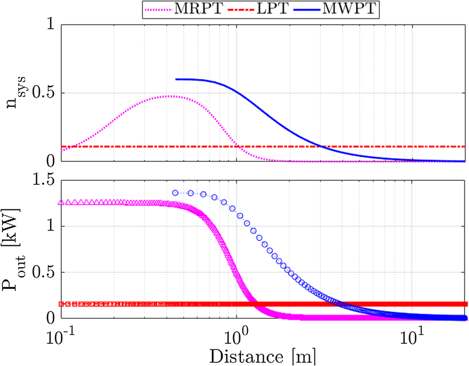
Fig. 9. System efficiency and power transfer as a function of transmission distance for magnetic resonance, laser, and microwave technology up to 20 m.

Fig. 10. System efficiency as a function of receiver diameter.
5. Discussion
This section discusses the results of the analysis and draws on recent advances in WPT technologies on possible improvements.
5.1. Propagation through mediums
5.1.1. Air
From Fig. 9, the transmission distance for MRPT and MWPT is limited to 1.04 and 1.3 m, respectively, for a power output of 160 W. The corresponding η sys at this distance is lower for both technologies compared to LPT. While the η sys for LPT is low at short- and mid-range, the efficiency is approximately the same even for long-range distances of up to 1 km [Reference Becker, Chiang, Keys, Lyjak, Nees and Starch33].
Increasing the resonant frequency of the MRPT does increase the transmission distance, although at only <0.1 m at 50 MHz. Operating at higher frequency also incurs losses in the power electronics circuit. Hence, MRPT tends to operate around the 100 kHz to 10 MHz range [Reference Sample, Meyer and Smith60, Reference Ishida and Furukawa94].
5.1.2. Optically translucent
MRPT has been shown to be insensitive to non-metallic obstacles [Reference Kurs53]. The transmission efficiency underwater for saline water was shown to decrease by 5% compared to in air while no decrease was recorded for pure and tap water [Reference Inamori and Morimoto95]. The loss is attributed to the dissolved salt increasing the dielectric losses. In [Reference Li, Li, Lin and Chen96], insulating the coils from direct contact with the seawater shows similar efficiency in air and underwater at atmospheric pressure. They proceeded to show that the increase in pressure decreases the transmission efficiency underwater at fixed transmission distance [Reference Li, Li, Lin and Chen96].
The transmission efficiency of MWPT and LPT through mediums decreases according to the absorption coefficient, μ a, in (11). A model of μ a is defined in [Reference Balanis97] as
 $$\mu _a = \omega \sqrt {\mu \epsilon} \left[ {0.5\left( {\sqrt {1 + {\left( {\displaystyle{\sigma \over {\omega \epsilon}}} \right)}^2} -1} \right)} \right]^{1/2}.$$
It can be seen that (17) is dependent on frequency (ω), surface conductivity (σ), dielectric permittivity (ε), and permeability of material (μ). The ε is frequency dependent and may be described by the Debeye or Jonschur models [Reference Bourdi, Rhazi, Boone and Ballivy98]. With each model consisting of three or more parameters, there are altogether at least six parameters that need to be identified for calculating μ a. The dependency of these parameters on environment factors means that the model is highly specific for a particular scenario.
In this study, the values for μ a are extracted from experimental data in the available literature where possible, or approximated. The μ a for pure water has been identified in [Reference Pope and Fry91] for the wavelengths considered in this study. The μ a for glass was extracted from the 20 mm glass thickness in [Reference Stone89] and is assumed to be linear.
Both LPT and MWPT attenuate quickly in water and glass as seen in Figs 8 and 7. The maximum transmission distance to achieve 10% efficiency is reduced to 0.1 and 0.8 m, respectively, for water, while transmission through glass is not feasible for both radiative technology as the efficiency is <10%.
While the η sys through pure water for LPT is slightly higher than MRPT between 0.7 and 1.1 m, it should be noted that the μ a used here corresponds to pure water. It is expected that the μ a will be higher in practical deployment scenarios, where the conductivity of the water has a proportional relationship to μ a [Reference Jiang and Georgakopoulos99]. Furthermore, losses arising from reflection, diffraction, and dispersion will result in even lower η sys. These observations are also applicable to MWPT.
5.1.3. Optically opaque
The opaque mediums considered are concrete, reinforced concrete, and metal. For MRPT, possible losses in the presence of magnetic components arise from the dielectric, hysteresis, and eddy currents [Reference Lee, Kim, Lee and Lee100]. The studies on MRPT through concrete have shown mixed results, where the η trans either decreases [Reference Jang, Han, Baek and Moon101], remains the same [Reference Ishida and Furukawa94], or increases [Reference Kim, Han and Sohn102]. This variation is attributed to the concrete mix which may be paramagnetic, thus affecting the coupling factor and the resonance frequency. Hence, the magnetic permeability of concrete cannot be assumed to be equivalent to free-space and needs to be evaluated experimentally.
The power loss for transmission through reinforced concrete tends to arise from hysteresis and eddy currents on the steel bar. Aligning the coils such that it sits between the space of the steel bars reduces the power loss by 10% when air core is used on the coils [Reference Jang, Han, Baek and Moon101]. This approach will require knowledge of the steel arrangement within the reinforced concrete so that the coil diameter may be designed to fit within the space. In practice, the coil alignment will require trial-and-error to identify the optimal position for maximizing the power transfer. However, using coils wrapped around a steel core results in a negligible power loss of 1% [Reference Ishida and Furukawa94], thus eliminating the need for finding the optimal position between the steel bar although at the expense of increased mass arising from the steel core.
The frequency of the system also dictates the losses, where high frequency tends to have lower penetrative capability [Reference Komurasaki, Mizuno, Ishida, Koizumi and Yamakawa103] and incurs higher eddy currents thus dominating the losses [Reference Lee, Kim, Lee and Lee100]. This type of loss was addressed in [Reference Ishida and Furukawa94, Reference Komurasaki, Mizuno, Ishida, Koizumi and Yamakawa103] by using low frequency, 50–60 Hz for transmission through 5–10 mm-thick metals and 100 mm reinforced concrete, respectively. In both these cases then, the losses are dominated by the hysteresis. Using low frequency results in a transmission efficiency drop of approximately 10% for a single layer of steel bar in reinforced concrete. For the setup in this study, the maximum transmission distance is limited to around 0.7 m for P out = 160 W.
Similar to the transmission through optically translucent mediums, the μ a for concrete and reinforced concrete have been estimated from [Reference Stone89], where the average values between the different concrete variations were used. Since the attenuation coefficient for both concrete and reinforced concrete is approximately the same, only concrete is shown here. MWPT through concrete shows significant attenuation where even at 0.4 m (start of radiative near-field), the n sys is almost zero. LPT was not considered for transmission through opaque materials as the wavelength is blocked by these materials and will result in power being dissipated as heat on the surface.
5.1.4. Comparison
Table 7 summarizes the performance of MRPT, MWPT, and LPT for the different mediums considered in this study.
Table 7. Comparison of WPT technologies transmission distance through various mediums.

The maximum transmission distance in the air is achieved using LPT followed by MWPT and MRPT. For transmission through non-air mediums, MRPT provides the maximum transmission distance at approximately 1 m compared to the other technologies. From Table 7, only LPT is capable of achieving the far-range transmission required in this study. However, this technology is only viable for transmission in air, limiting its application to ground robots and UAVs. Although underwater robots can rise to the surface to be charged using LPT, doing so results in the robot deviating from its mission, which is no different from returning to a docking station hence is not viable.
For underwater robots, MRPT is more feasible since the attenuation underwater is negligible if the coils are isolated from the surrounding water as shown in [Reference Li, Li, Lin and Chen96]. The attenuation from the surrounding pressure on the transmission efficiency does not need to be accounted for the two robots considered here since the maximum depth of both these robots is 100 m, well below the depth at which attenuation becomes non-negligible [Reference Li, Li, Lin and Chen96]. It should be noted that the transmission range will be <1 m since the receiver area for both the AVEXIS and BlueROV is smaller than the Husky (the effect of the receiver area on the transmission range will be discussed shortly). Land and air robots that do not have LOS, such as operating behind a glass or concrete wall, will have to rely on MRPT. Similar constraints on the range and mobility of underwater robots and land/air robots are observed.
It is understood that the approximations of μ a are a limitation to this study as these values may vary widely. While the results in [Reference Stone89] show a linear relationship between the concrete thickness and receiver gain, a non-linear relationship is observed between the glass thickness and receiver gain. Hence, in-situ measurements will be required to determine μ a for the wavelength used and subsequently the transmission efficiency through these mediums. Despite the approximation used, the fundamental limitation of propagation through a non-air medium has been highlighted here for the use of radiative power transfer technologies.
5.2. Receiver requirements
A typical receiver setup consists of a power converter, ancillary electronics, and subsystems such as battery management system and control system (allows communication between the transmitter and receiver for tasks such as, but not limited to, power transfer initiation and termination, power output required, impedance matching). The focus in this section is on the required power converter and its ancillary components for MRPT, MWPT, and LPT, used on the robots highlighted in subsection B.
5.2.1. MRPT and MWPT
The dependency between the η sys and the receiver diameter, shown in Fig. 9, means that the η sys for MRPT and MWPT will decrease with the diameter of the receiver area. This decrease means that robots with smaller receiver area availability will have lower system efficiency for the same transmission distance. Power transfer of MRPT is further limited by the heat generation on the coils arising from conduction, hysteresis, and eddy current losses [Reference Rim and Mi104]. The need for a cooling system, typically in the form of passive heat sink, will increase the mass and volume of the system.
5.2.2. LPT
From Fig. 9, the η sys for LPT is independent of the receiver size (assuming that temperature of the LPC is maintained). Hence, the area of the receiver may be minimized to the same size as the collimated beam while still achieving the same efficiency. The LPC size is scaled according to the power requirement as each cell on the LPC has a limited power output. The LPC required for the Husky is only 2.7 × 10⁻³ m2, much smaller compared to the other two technologies which occupy the maximum permissible receiver size (0.3 × 0.3 m2).
An important consideration in the use of LPT is the LOS requirement between the receiver and transmitter. The high intensity of laser used is hazardous and hence should only be pointed to the LPC which is able to withstand the laser intensity. This requirement will need a tracking mechanism, such as visual servoing [Reference Achtelik, Stumpf, Gurdan and Doth81] or laser guard beams [Reference Iyer, Bayati, Nandakumar and Majumdar79] as part of the control system for initiating the terminating power transfer according to alignment.
The LPC requires a cooling system which serves to dissipate the heat generated due to the low efficiency of LPC, and optimizes the efficiency of the LPC by maintaining the temperature of the LPC at an optimal temperature. Available heat sinks indicate that the setup for Z th = 0.05°C/W requires a volume of 0.3 × 0.1 × 0.07 m3 with two fans (2.4 W each) attached. This setup is approximately half the maximum permissible receiver size and is expected to weigh <2 kg. Since the Husky has a payload capability of 75 kg, the cooling setup is realizable for this robot. A similar or scaled-down setup can be used on the Jackal which would meet the power requirement without compromising the payload availability of the robot.
However, the LPC for the ANYmal, Corin, Phantom, and Matrice has to be operated at non-optimal temperatures or under-powered. This is due to the thermal impedance and low payload capability of these robots, which prevent the use of an active cooling system. The same cooling setup on the Husky can be used for the Matrice, although this corresponds to taking up 33% of the payload. The limited payload capability of both the Corin and Phatom robot severely limits the use of a heat sink for the required thermal impedance. A possible solution to this is to use a lower incident power or intermittent charging to prevent damage to the LPC from overheating.
5.3. Human safety considerations
An important factor in the use of WPT is the health and safety issues of using these technologies in the presence of humans. The power requirement of the robots considered, coupled with the low system efficiency of the three WPT technologies considered, results in high-power emission of either magnetic field or electromagnetic radiation. Exposure of humans to these emissions needs to adhere to standards set by government and non-government organizations.
5.3.1. Magnetic field
The emission for electromagnetic WPT technologies needs to adhere to the ICNIRP Guidelines for Limiting Exposure to Time-varying Electric, Magnetic, and EMF (up to 300 GHz) [105] and the IEEE Standard for Safety Levels with Respect to Human Exposure to Radio Frequency EMF 3 kHz to 300 GHz. Exposure limit for humans need to be identified using EM simulation software such as COSMOL in [Reference Ding, Bernard, Pichon and Razek106] or SEM-CAD X in [Reference Christ107] for MRPT. Rough estimates indicate a radius of 1 m from the transmitter location is within the safety limit.
5.3.2. Electromagnetic radiation
For MWPT, the power density limit for the ICNIRP limit at 2.4 and 5.8 GHz are 50 W/m2. The power density is calculated as
 $$S = \displaystyle{{P_{tx}G_t} \over {4\pi d^2}},$$
where P tx is the power transmitted, G Tis the antenna gain, and d is the transmission distance.
Assuming P in = 1.6 kW for $n_{{\rm sys}} = 10\% $ at d = 3.12 m and G t = 25 dB, the power density is 808 W/m2, significantly above the permissible limit. This renders the transmission path inaccessible to humans. A safety boundary also needs to be included due to beam divergence. A possible solution is to use power waveforming, where the RF power is transmitted to the receiver through multipath, thus distributing the power density [Reference Ku, Han, Lai, Chen and Liu108]. However, the authors have their reservation on the feasibility of dispersingP tx = 1.28 kW in a multipath fashion such that the power density safety limit is adhered to.
The high power of LPT required in this study is categorized as a Class 4 laser. This means that necessary safety measures must be put in place to avoid human exposure, such as dedicated rooms, remote viewing, or the use of safety glasses by anyone within viewing the proximity of the laser [Reference Smalley109]. An indicator of the accessible range along the axis of the transmitted beam is the nominal ocular hazard distance (NOHD), described by
 $$NOHD = \theta ^{-1}\sqrt {\displaystyle{{4\phi} \over {\pi M}}-d_{{\rm out}}^2}, $$
where θ is the beam divergence, ϕ is the laser radiant power, Mis the maximum permissible exposure, and d out is the output beam diameter.
Assuming θ = 0.001 rad, ϕ = 408 W, M = 25 W/m2, and d out = 0.060 m, the NOHD = 4.6 km. This means that the entire length along the transmission path is considered hazardous. However, the small beam divergence and output beam diameter mean that only a small boundary area is required. To avoid injury from accidental exposure to the high laser beam, guard beams have been proposed to interrupt the beam transmission when unidentified objects enter into the beam area [Reference Iyer, Bayati, Nandakumar and Majumdar79]. Since a distance of only 12 mm between the guard beam and the high power beam is required [Reference Iyer, Bayati, Nandakumar and Majumdar79], the overall width for a distance of 20 m is only 84 mm. This width is relatively small compared to the robot's width. Although the use of guard beams eliminates the risk of direct exposure to the beam, the electromagnetic radiative effect will still require safety measures and boundaries to avoid radiative damage to humans. Hence, the deployment of LPT presents substantial health hazards and would benefit from having no humans working within the same environment.
5.4. Practical applications
Table 8 summarizes the analysis and discussions, providing a comparison of the different technologies in air and non-air mediums, and the relevant design considerations. Alignment here means that the transmitter and receiver are aligned axially, while LOS means that the transmitter and receiver are aligned with no obstacles (only air) between them.
Table 8. Comparison of WPT technologies transmission distance through various mediums.

Common to all three technologies is the need for a tracking mechanism to meet the alignment requirement as the system efficiency decreases with misalignment. A combination of visual and RF signal tracking in [Reference Iyer, Bayati, Nandakumar and Majumdar79] for LPT allows fast and accurate positioning compared to using only a single approach. This approach is also suitable for MWPT. For MRPT, a possible approach to the alignment problem, in addition to frequency or impedance matching [Reference Sample, Meyer and Smith60], is to characterize the power distribution over a range of misalignment. The power distribution may then be used to determine the misalignment vector in which the robot can then make the necessary motions to achieve alignment.
From Table 8, it can be seen that among the three technologies, MWPT has the poorest performance as it is only capable of mid-range transmission in air. MRPT is capable of mid-range transmission through mediums while LPT is capable of far-range transmission in air. Hence, using MWPT in this context has no clear benefits. For non-air transmission, MRPT provides the highest system efficiency hence well suited to such a scenario. However, the aim of extending the robot's operational time without compromising on its mobility is unachievable as the transmission distance is limited to mid-range. Despite this limitation, a benefit of using MRPT arises in deployment scenarios where the access is sealed or there are no feasible docking stations in the operational environment for the robot, subject to the medium being <1 m thick.
For transmission in air, LPT is the better choice in terms of transmission distance. However, the primary limitation of this technology is the LOS requirement. Deployment scenarios are likely to have obstacles present, thus the use of LPT will require significant supporting structures (beam relays or overhead laser beaming) to be put in place. These supporting structures present additional challenges such as visual servoing, strategic placement position for full coverage, design, and mounting of the systems. In scenarios where the deployment of these supporting structures is unavailable, the robot's mobility will be severely limited to a straight line only.
With regards to the aim of extending a mobile robot's operational time without compromising on its mobility, none of the current available WPT technologies is able to meet this aim without requiring significant supporting infrastructure. Despite the limitations of WPT technologies, there are special scenarios where using WPT presents a clear advantage, such as far-range LOS or sealed access requiring through-wall power transmission. The state of the current technology is able to support WPT in both these scenarios and is possible for immediate deployment.
6. Conclusion
The application of WPT technologies on mobile robots has been reviewed in this paper and the feasibility of state-of-the-art WPT technologies for a select case of robots operating in different environments analyzed. There are six WPT technologies, APT, CPT, IPT, LPT, MRPT, and MWPT. Among these, LPT, MRPT, and MWPT are able to achieve mid- to far-range transmission distance with a smaller receiver area compared to the other three. The system performance through different transmission mediums and receiver requirements has been analyzed. LPT showed the highest system efficiency at far-range in air transmission while MRPT shows the highest system efficiency for non-air transmission mediums which include water, glass, concrete, and reinforced concrete. The safety considerations for mid-power transmission of these three technologies have been considered, in which all three present themselves as hazardous even at mid-power. The practicality of using existing WPT technologies, considering the challenges of delivering the power required at mid- to far-range distances for non-stationary mobile robots, is limited as reviewed in the literature and analysis in this research. Similar to existing applications of WPT for mobile robots, scenarios which WPT can be readily used are near- to short-range distances, similar to the docking station, and long-range with LOS.
Financial Support
This work was supported by UK Research and Innovation through the Engineering and Physical Science Research Council under grant number EP/P01366X/1.
Conflict of Interest
None.
Ethical Standards
None.
 Wei Chen Cheah received his M.Eng. degree in mechatronics engineering at the University of Manchester in 2015. He is currently working toward his Ph.D. and is a research associate with the Robotics for Extreme Environment Group at the University of Manchester. His main research interests are mobile robots and wireless power transfer.
 Simon Watson is a senior lecturer in robotic systems in the School of Electrical and Electronic Engineering at the University of Manchester. He obtained his M.Eng. in mechatronic engineering in 2008 and his Ph.D. in 2012, both from the University of Manchester. His research focus is on mobile robots for the exploration and characterization of hazardous and extreme environments and active areas of research include novel platform design, communications and localization and sensing and navigation. His current research portfolio includes developing submersible, wheeled, and legged robots for the nuclear industry (for the Sellafield and Fukushima sites) and aerial robots for the power generation industry (offshore wind).
 Barry Lennox is professor of applied control and nuclear engineering decommissioning in the Department of Electrical and Electronic Engineering at the University of Manchester and director of the Robotics and Artificial Intelligence for Nuclear (RAIN) Research Hub. He is an expert in applied control and its use in robotics and process operations and has considerable experience in transferring leading edge technology into industry. He is the research lead for the nuclear engineering decommissioning theme within the Dalton Nuclear Institute and the Robotics in extreme environments theme within the School of Electrical and Electronic Engineering. He leads the EPSRC Programme Grant: Robotics for Nuclear Environments and the robotics work within the EPSRC TORONE project.


 Open access