


Introduction
The loss of Sir John Franklin’s 1845 expedition (HMS Erebus and HMS Terror) remains a major case study in the archaeology and historiography of nineteenth-century polar exploration. A central documentary anchor is the “Victory Point” record, retrieved in May 1859 by Lieutenant William R. Hobson during the search expedition led by Captain (later Admiral Sir) Francis Leopold McClintock. The marginal note dated 25 April 1848 reports that the ships had been beset since September 1846 and were deserted on 22 April 1848, leaving 105 survivors who intended to depart on 26 April for Back’s (Great Fish) River (McClintock, Reference McClintock1860).
The 1859 search also identified the archaeological site now designated NgLj-3 on the west shore of King William Island in Erebus Bay. At this locality, Hobson and McClintock examined a large ship’s boat mounted on a heavy sledge and containing equipment and human remains. Their accounts describe conspicuous structural modification for over-ice and/or river travel, including reduced weight, altered upperworks planking, and a weather-protection system supported by iron stanchions (McClintock, Reference McClintock1860; Stenton, Reference Stenton2014; Stenton & Park, Reference Stenton and Park2017).
Since the discoveries of HMS Erebus in 2014 and HMS Terror in 2016, underwater archaeology has shifted the evidentiary landscape by revealing shipboard contexts potentially contemporary with the expedition’s final years. Among the features documented at the HMS Terror site is a 23-foot cutter adjacent to the wreck (Figure 1).
HMS Terror site sketch showing major features and the location of the cutter adjacent to the wreck.
Source: Parks Canada (2025), site sketch as of 2017.

The question addressed here is not whether the wreck-site boat was the same class as the 28-foot, double-ended boat recorded at NgLj-3 in 1859; it was not. Rather, the present study asks whether the wreck-site cutter preserves image-visible features consistent with elements of the NgLj-3 modification suite, namely altered upperworks, a depressed rail or sheer line, and rail-mounted uprights compatible with a weather-cloth/thowell system. Any such correspondence would suggest that similar field modifications may have been applied to more than one expedition boat. It would not, by itself, establish when those modifications were made or whether any party later attempted to return to the ships.
Here, I present a focused, reproducible assessment of the available still imagery of the Terror wreck-site cutter, explicitly framed as a hypothesis test against historically described NgLj-3 modifications. The aim is to (i) document measurable and repeatable features in the available imagery, (ii) compare those features to primary accounts and museum-held comparators associated with NgLj-3, and (iii) define testable predictions for future survey work. The results are also discussed briefly in relation to the long-standing hypothesis of a return to the ships, but that broader historical question is not required to sustain the paper’s main argument.
Historical and comparative framework
The 1859 NgLj-3 accounts
Lieutenant Hobson was the first to examine the boat at NgLj-3 on 24 May 1859; Captain McClintock reached the site six days later and published the fuller account. Together, their descriptions depict a large, double-ended boat on a heavy sledge, measured at 28 feet in length, and materially altered for travel. Hobson emphasised that the craft had been lightened, remarking that all iron and woodwork that could be dispensed with had been removed and that the surviving upperworks were exceedingly light and clinker-built (Stenton, Reference Stenton2014).
McClintock added the more specific observation that the upper seven strakes had been replaced with very thin fir planks fitted in clinker fashion and that a 9-inch canvas weather-cloth was supported by 24 iron stanchions placed so as also to serve as thowells (McClintock, Reference McClintock1860).
These descriptions are central to the present comparison, but they are not a complete construction record. Some alterations are explicit, while others remain only partially described. The NgLj-3 material therefore permits a comparison of modification themes rather than a full reconstruction of every structural change.
Boat complements and the relevance of the Terror cutter
An Admiralty office record transmitted to McClintock in 1881 lists each ship as having been fitted out for Arctic service with nine boats: one 28-foot pinnace, one 30-foot Tilley, two 30-foot whalers, two 25-foot cutters, one 23-foot cutter, one 22-foot gig, and one 12-foot dinghy (British Admiralty, 1881). On that basis alone, the 23-foot boat adjacent to HMS Terror cannot be equated with the 28-foot NgLj-3 craft.
A further complication is that the boats actually carried westward from Greenland may not have matched the earlier establishment exactly. In a letter written from the Whalefish Islands on 9 July 1845, Francis Crozier noted that he had sent home Terror’s “largest cutter” and a launch with patent fuel in order to reduce weight (Crozier, Reference Crozier1845). The original establishment nonetheless remains useful as a baseline for what had been supplied, and it underlines that a 23-foot cutter formed part of each ship’s boat complement.
The present comparison is therefore deliberately narrow. It does not attempt to identify the wreck-site cutter as the NgLj-3 boat nor to collapse a 23-foot cutter into a 28-foot double-ended craft. Instead, it tests whether a smaller cutter may preserve features consistent with the same general pattern of field modification described at NgLj-3.
Museum-held comparators and dimensional controls
Two categories of NgLj-3-derived objects are relevant as comparators. First, iron stanchions attributed to the boat’s weather-cloth support system survive in the Royal Museums Greenwich collections. One published example (AAA2143.1) measures 301 × 25 × 20 mm and provides a dimensional comparator for the candidate upright observed on the wreck-site cutter (Royal Museums Greenwich, n.d.a).
Second, the surviving bow/keel fragment AAA2282 provides a museum-held example of a materially altered boat-end assembly associated with the Erebus Bay remains. In view of the continuing discussion surrounding the stem marking on AAA2282, however, the numeral record is not treated here as diagnostic evidence for the donor boat’s original class. The value of the object for the present paper lies more simply in its status as a dimensional and morphological comparator for a cut-back bow/keel fragment (Royal Museums Greenwich, n.d.b).
Contemporary cutter plans as morphological baselines
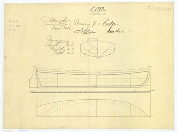
To evaluate whether the wreck-site cutter exhibits anomalous sheerline behaviour and bow timber proportions, the analysis uses Admiralty-era cutter plans from the National Maritime Museum/Royal Museums Greenwich collections, especially the 23-foot cutter plan dated January 1852 (object ZAZ7031; image reference J0749; Figure 6). These plans provide a reference for the expected relationship between the rail or sheer strake and the stemhead on contemporaneous Royal Navy cutters (Royal Museums Greenwich, n.d.c.).
Materials
Underwater imagery of the Terror wreck-site cutter
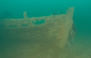
The primary observational dataset consists of the still frames and still photographs available to the author at the time of writing (Figure 2). These show the bow and starboard sides of a ship’s cutter adjacent to HMS Terror, including (i) a prominent stempost/stemhead timber, (ii) a surviving gunwale/rail segment with a vertical protruding feature (candidate upright), (iii) an extended gap or void immediately below the rail where upper hull planking is absent, and (iv) lower hull planking with discernible horizontal texture.
Underwater still image of the bow and starboard side of the cutter adjacent to HMS Terror, showing the stemhead timber, surviving gunwale/rail, and a large sub-gunwale void.
Source: Photography published by Parks Canada (2025).

No higher-resolution, multi-angle survey set was available to the present study. The analysis therefore aims to be explicit about what can and cannot be inferred from the existing still imagery.
Site context imagery
For contextual placement the study uses Parks Canada’s HMS Terror site sketch, which identifies the wreck site boat as a cutter and shows it lying adjacent to the ship’s stern structures (Figure 1). The same site documentation shows wreck material overlying the stern of the cutter, making it most economical to interpret the boat as having gone down with the ship, probably from the port quarter davits, although the present paper does not attempt a full site-formation analysis (Parks Canada, 2018; Parks Canada, 2025).
Comparative images
Comparative material includes the Admiralty 23-foot cutter plan used as a baseline for expected sheerline and bow geometry (Figure 6), together with the author-generated analytical figures used to illustrate measurement, profile, and edge-detection results (Figures 3–5, 7–9). These figures are used strictly for geometric and visual comparison rather than as a basis for detailed construction specifications.
Candidate upright feature measurement. The red line indicates estimated protrusion above the gunwale; the green line indicates the scaling baseline from the gunwale to the lowest definable hull boundary in the same transect (section candidate upright sizing).

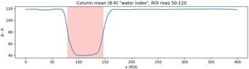
Example ROI-based profiles around the candidate upright: column-wise mean greyscale intensity and water-index (W) profiles used to test for a paired-upright (thowell) water-gap. The analysed frame does not resolve a consistent central gap indicative of two uprights.

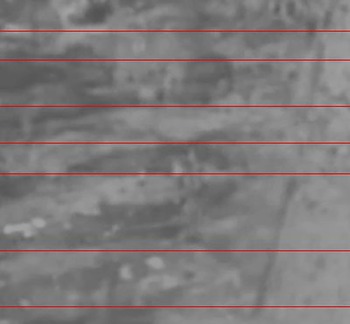
Bow-side ROI with gradient-peak-based horizontal seam detection (red lines) illustrating repeated lower-hull boundary signatures used to support the interpretation of preserved lower planking.

Admiralty-era 23-foot cutter plan dated January 1852 (Royal Museums Greenwich object ZAZ7031; image reference J0749) used as a baseline for expected sheerline/stemhead geometry.

Sub-gunwale degraded zones and seam peaks are used for Delta y and n estimates.

Edge-density profile highlighting the degraded zone between the gunwale and the first intact seam.

Bow crop showing stem-end width sampling relative to gunwale level.

Methods
Overview and reproducibility
All image analysis was conducted in Python using Pillow, NumPy, OpenCV, SciPy, and Matplotlib. The workflow was designed to be repeatable on the supplied still images and is organised into four analytic modules: (A) preprocessing and enhancement; (B) candidate upright sizing; (C) paired-upright (thowell) void testing; and (D) plank/strake texture analysis.
Preprocessing
Images were converted to RGB arrays and, where relevant, to greyscale. To improve the visibility of subtle wood-water boundaries, contrast-limited adaptive histogram equalisation (CLAHE) was applied to the greyscale channel. For wood-water segmentation, a simple colour index was used to emphasise the red-blue contrast typical in underwater imagery: W = (G + B)/2–R. Higher W indicates water-dominated pixels; lower W indicates wood- or sediment-dominated pixels. Indices were normalised to the interval [0,1] for thresholding.
Candidate upright sizing
The apparent protruding height of the candidate upright above the gunwale was measured in pixels along a fixed vertical transect intersecting the feature (Figure 3). Because no direct scale object exists in the image, the pixel-to-length conversion was anchored using the nominal moulded depth of a 23-foot cutter (2 feet 6 inches; 0.762 m) as indicated on the Admiralty plan used as a baseline. Specifically, the pixel distance from the gunwale down to the lowest visually definable hull boundary in the same transect was measured and treated as an approximate proxy for the true keel-level depth. This is an upper-confidence scaling method and is used only for order-of-magnitude comparison to the 9-inch weather-cloth height reported by McClintock (Reference McClintock1860).
Paired-upright (thowell) testing
McClintock described the NgLj-3 stanchions as placed so as to serve as rowing thowells, implying paired supports with a gap between them. To test whether the candidate upright in the Terror imagery could represent such a paired arrangement, a region of interest (ROI) around the feature was extracted and used to compute (i) column-wise mean greyscale intensity, (ii) column-wise mean water-index (W) values, and (iii) a simple two-class segmentation in W-space to separate water-like pixels from solid/object pixels (Figure 4). A true paired-upright geometry should produce a central column region with elevated W bounded by two object peaks.
Upperworks void and strake/texture analysis
To assess whether upper planking may have failed differentially, the maximum vertical extent of the upper-hull void zone beneath the gunwale was measured using the water-index profile. Within a defined ROI spanning the hull side, the fraction of water-like pixels per image row was computed and used to identify the principal sub-gunwale zone of increased background water visibility.
Separately, to assess whether lower planking retains repeated horizontal seam signatures continuing toward the bow, a bow-side ROI with visible banding was extracted, averaged across columns to produce a one-dimensional vertical profile, and differentiated to identify prominent gradient peaks that may correspond to plank seams or edges (Figure 5). The resulting seam spacing is used only as a rough comparator to the void zone thickness; it is not treated as a definitive strake count.
Delineating the gunwale/rail and the sub-gunwale degraded zone
A bow-side ROI was contrast-enhanced, edge-detected, and masked to the hull using a blue-red colour index with morphological closing. Summed edge pixels per row (edge density) yield a one-dimensional profile in which persistent horizontal boundaries appear as peaks. The gunwale/rail is operationally defined as the strongest upper hull peak and the top intact seam as the first continuous high-contrast seam below the degraded upperworks. Their separation, Delta y, quantifies the degraded-zone height (Figures 7 and 8).
Missing-strake estimate
Inter-seam spacing, s, was measured from stable seam peaks in the intact lower hull immediately beneath the degraded zone. The strake-equivalent count was then calculated as n = Delta y/s and is reported as a continuous estimate with bounds reflecting peak-picking uncertainty and the possibility of seam doubling.
Stem-end width sampling
A bow crop was segmented using a normalised redness ratio. For rows above the gunwale, the width of the largest contiguous timber/concretion segment was recorded (Figure 9). Pixel widths are converted to a context-only physical range using the same vertical scaling baseline employed elsewhere, recognising substantial perspective and concretion uncertainty.
Limitations
Key limitations include primary image resolution, water turbidity, variable illumination, biological encrustation, perspective distortion, partial burial, and unknown camera geometry. Consequently, all metric results are reported as approximate and are used primarily for comparison to historically reported orders of magnitude rather than as final archaeological measurements.
Results
Site context
The boat analysed here is not re-identified in this paper. Parks Canada’s site documentation already treats it as the 23-foot cutter associated with HMS Terror, and its position on the seabed has been interpreted as consistent with a boat hanging from the port quarter davits at the time of sinking (Figure 1; Parks Canada, 2018). The still imagery used in the present study shows only the bow and starboard-side portion of that boat (Figure 2). Accordingly, the purpose of this section is not to determine whether the craft was double-ended or transom-sterned but simply to define the portion of the hull visible in the analysed frames and the limits that this imposes on interpretation.
Candidate upright feature and approximate dimensions
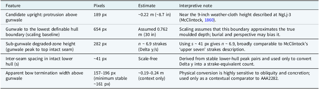
A prominent vertical feature is visible on the surviving rail/gunwale (Figure 3). In the analysed frame, the protruding height above the local gunwale line is approximately 189 pixels along the measurement transect. The pixel distance from the gunwale to the lowest visually definable hull boundary in that transect is approximately 654 pixels. Assuming a 23-foot cutter depth of 30 inches (0.762 m), this yields an estimated protruding height of: $\eqalign{ {\rm h\; approximately\; equals\; (189/654)\; \times \;0.762\; m\; approximately\;} \\ { 0.22\; m\; (about\; 8.7\; inches).}}$
This is notably close to the 9-inch weather-cloth height described at NgLj-3 (McClintock, Reference McClintock1860). It is also broadly compatible with the approximately 0.30 m overall length of the published RMG stanchion example AAA2143.1, especially if the museum measurement includes the portion seated below the gunwale or into a socket (Royal Museums Greenwich, n.d.a). Because the reference depth in the image may not represent true keel depth, the 0.22 m estimate should be treated as approximate. Plausible error bounds of plus or minus 25% (roughly 0.17–0.28 m) still encompass the reported weather-cloth height.
Paired-upright (thowell) void testing
ROI-based profiles of greyscale intensity and water-index values show a single broad object region corresponding to the upright feature, with no consistently resolved central water gap that would indicate two separate uprights (Figure 4). Two-class segmentation similarly classifies the feature as a single contiguous object at the available resolution. Accordingly, the present imagery cannot confirm whether the feature represents a paired thowell arrangement, a single upright, a timber knee, or an encrusted remnant of another fitting.
Sheerline relative to stemhead: qualitative comparison to Admiralty plans
In the underwater imagery, the surviving rail/gunwale line sits markedly below the highest preserved portion of the stemhead timber, leaving a substantial vertical segment of stem above the rail (Figure 2). In the comparative Admiralty 23-foot cutter plan (Figure 6), the rail/sheer strake rises toward and approaches the stemhead, maximising bow freeboard and reducing green-water ingress. The observed mismatch at HMS Terror is therefore anomalous relative to the planned baseline and is consistent with either (i) deliberate lowering or truncation of the gunwale during field modification or (ii) post-depositional loss of the uppermost strakes and the original sheer strake, leaving a lower surviving rail element.
Upperworks void zone, lower-plank continuity, and taphonomic caution
Water-index segmentation reveals a discrete zone immediately below the surviving rail where the fraction of water-like pixels increases relative to both the rail itself and the lower hull, indicating increased background water visibility through missing structure. In a representative hull-side ROI, the principal sub-gunwale void zone spans approximately 121 pixels in height. Because the void zone is laterally heterogeneous, this row-averaged estimate likely understates the maximum local gap visible in the image.
Gradient-based detection in a bow-side ROI identifies repeated horizontal seam signatures consistent with preserved plank boundaries in the lower hull (Figure 5). Taken together, these findings are consistent with a preservation pattern in which a subset of the upper planking has been lost preferentially. This observation is what one might expect if these upper strakes were less robust than the lower ones and therefore eroded more rapidly.
However, an important taphonomic caution is required. Upper hull planking might be expected to fail earlier than lower planking even without deliberate thinning because the upperworks are more exposed, less laterally supported, and further from the partial protection of burial. The observed sub-gunwale void is therefore not, on its own, evidence of lightened replacement strakes. Its interpretive value in the present case lies in its conjunction with two other features: the anomalously low surviving rail relative to the stemhead and the candidate upright on the rail.
Seven-strake signal beneath the gunwale
The edge-density profile yields a strong upper boundary at approximately y = 417 px (gunwale/rail) and a first continuous seam at approximately y = 699 px, giving a Delta y of approximately 282 px (Figures 7 and 8). Several weaker, discontinuous edges occur within this band and are consistent with the fragmentary survival of upper planking. Using s approximately 41 px from the intact lower hull, n = Delta y/s yields approximately 6.9 strake heights. This correspondence with McClintock’s statement that the NgLj-3 boat had its “upper seven” strakes replaced is suggestive only. Given the sensitivity of the estimate to ROI choice, seam selection, and degradation, it should be treated as a rough scale comparison rather than a definitive strake count.
Bow termination width
In the bow crop, the largest timber/concretion segment above the gunwale measures 157–196 px, with a minimum stable value of roughly 161 px (Figure 9). Using the same scaling baseline, this corresponds to an apparent forward-face width of roughly 0.19–0.24 m. This exceeds the 103 mm moulded thickness of the recovered bow/keel fragment AAA2282 (Royal Museums Greenwich, n.d.b.), implying strong concretion and/or obliquity effects or a broader cut-back bow termination rather than the stem timber alone.
Summary of measured quantities
Table 1 summarises the principal metric outputs derived from the analysed frame. These values are intended as comparative indicators, not final archaeological measurements.
Summary of key image-derived measurements (representative frame)

Discussion
Convergence with the NgLj-3 modifications
The NgLj-3 accounts describe three major physical themes: (i) systematic weight reduction, including the removal of dispensable iron and woodwork; (ii) altered upperworks planking using thin fir fitted in clinker fashion; and (iii) a weather-protection system comprising a 9-inch canvas weather-cloth supported by iron stanchions that also functioned as rowing thowells. The Terror wreck-site cutter imagery is consistent with at least two of these themes: a depressed or truncated rail relative to the stemhead and a conspicuous sub-gunwale void zone consistent with missing upperworks. The candidate upright feature also yields an exposed height close to 9 inches when scaled by nominal cutter depth.
None of these signals is diagnostic in isolation. Their significance lies instead in their convergence. A low surviving rail, a void beneath it, and a rail-mounted upright form a cluster of observations more suggestive of a modification suite than any single observation considered alone.
Interpreting the stanchion candidate: alternative explanations
The still imagery does not resolve whether the candidate’s upright is iron or wood, nor whether it represents a paired thowell arrangement. Alternative explanations include a surviving timber stanchion or oarlock post from the cutter’s original fit, an encrusted fragment of boat-handling gear, or a post-depositional deformation that makes a single structure appear more prominent. Even so, the combination of size compatibility with known NgLj-3 stanchions and the feature’s location on or near the rail – where a stanchion or thowell would be expected – makes it archaeologically plausible as part of a weather-cloth/thowell system.
Stem-end modification and the comparator value of AAA2282
AAA2282 remains useful to this paper because it demonstrates that a materially altered boat-end assembly associated with the Erebus Bay remains survives in museum collections. The Terror imagery likewise suggests a possible reduction or loss of the forward timber profile, but the image record is insufficient for a reliable metric comparison to the Admiralty plan or for the identification of fastener-hole evidence that might clarify how the bow was modified. Any inference of deliberate stem reduction at the wreck-site cutter must therefore remain tentative until higher-resolution photogrammetry, multi-angle imaging, or direct measurement becomes available.
What the comparison does and does not imply
The present observations do not resolve whether any Franklin party later attempted to return to the ships, and that question is not necessary to the main argument. At most, the wreck-site cutter suggests that a boat remaining with HMS Terror may have carried some of the same kinds of alterations described at NgLj-3.
That possibility is compatible with several logistical scenarios, including preparations made before the April 1848 abandonment, preparations made but not fully implemented, or later reuse or reworking by a smaller party. The current image set cannot discriminate among these possibilities, so broader historical inferences should remain limited. McClintock’s hypothesised return to the ships is one possible context, but the current evidence cannot support this.
Boat complements, logistics, and selective retention
The boat-complement evidence matters because it clarifies what would follow if a 23-foot cutter had indeed been modified. The speculative finding implies that adaptation efforts were not restricted to a single large 28-foot boat but extended to smaller craft within the expedition’s surviving complement. That pattern fits a regime of distributed contingency preparation rather than a uniquely altered boat; this agrees with Inuit oral histories and existing archaeological evidence.
The Victory Point note records 105 survivors at the time of intended departure in April 1848 (McClintock, Reference McClintock1860). Even under optimistic assumptions of boat capacity, moving that number of people and their essential supplies by small boats would have required multiple craft and careful load management. Crozier’s July Reference Crozier1845 letter already shows that boat and weight rationalisation had begun before the expedition disappeared (Crozier, Reference Crozier1845). It is entirely possible that the Terror cutter was modified but left with the ship; that fact would be compatible with selective retention of some prepared boats and the non-use, non-survival, or later abandonment of others. The present evidence cannot determine whether the boat was modified before abandonment, retained unused, or altered in another logistical context. However, the available site evidence of the cutter’s position is consistent with the boat having remained at or near its davits at the time of sinking.
Future work
If further direct archeological assessment is not currently planned, to move beyond plausibility and establish whether the Terror wreck-site cutter was deliberately modified in the same manner as the NgLj-3 boat, future work could prioritise (i) assessment of further photogrammetry of the cutter’s bow, gunwale, and upperworks; (ii) specific identification of thowell sockets or iron fastenings consistent with removable stanchions; (iii) if available the measurement of plank-thickness gradients from lower hull to upperworks; and (iv) if possible closer comparison to museum-held NgLj-3 components. Such work would also allow a better assessment of whether the low rail reflects true modification, later loss, or some combination of both without major further expedition endeavours.
Conclusions
Available still imagery of the 23-foot cutter adjacent to HMS Terror is consistent with several elements of the modification suite described for the NgLj-3 boat, especially a low surviving rail relative to the stemhead, a sub-gunwale loss zone compatible with removed or missing upperworks, and a rail-mounted upright of approximately the right order of magnitude for a weather-cloth support.
None of these observations is individually diagnostic, and the imagery cannot distinguish deliberate alteration from later damage with confidence. Taken together, however, they justify the narrower conclusion advanced here: that the wreck-site cutter merits serious consideration as a possibly field-modified expedition boat and should be documented further if new survey opportunities arise.
Acknowledgements
This text utilises publicised work from Parks Canada and the open-source repository available from the National Maritime Museum, Greenwich, UK. Artificial intelligence assistance was used during manuscript preparation. OpenAI ChatGPT was used in 2026 to assist with Python coding for image-processing workflows and editing. All outputs were reviewed and verified by the author, who takes full responsibility for the final content.
Financial support
This research received no specific grant from any funding agency, commercial or not-for-profit sectors.
Competing interests
The author(s) declare none.


 Open access