


1. Introduction
Inexpensive digitisation devices which operate at radio frequencies, known as ‘Software Defined Radios’ (hereafter SDRs), are bringing radio astronomy into the domain of the amateur radio astronomer. Small satellite dishes, in the range of 0.5-3 m, are also readily available at low cost, as is a range of open-source, professional radio astronomy software for data processing and display. Consequently, a range of small telescope designs have been appearing over the last decade, suitable for use by amateur astronomers, or for teaching purposes for high school students and STEM (Science, Technology, Engineering, and Mathematics) outreach. Science goals of such projects have included monitoring of radio frequency (RF) activity of Sun, detecting and measuring the kinematics of the spiral arms of the Milky Way galaxy via 21 cm emission, satellite tracking and data acquisition and the detection of radio pulsars.
In this paper, we describe a low-cost, fully operational 2.4 m radio telescope located near Woodchester in South Australia (hereafter, the Woodchester Observatory) with which we perform daily timing observations of the radio pulsar J0835−4510 (the ‘Vela Pulsar’). A primary goal of the project was to demonstrate that a low-cost system that can be assembled and operated starting from a low experience base and do useful scientific observations of the Vela pulsar.
Pulsars are well known to undergo occasional sharp jumps in their periods of rotation, known as ‘glitches’. They are especially frequent in younger, slow pulsars, with Vela being one of the most prominent cases. In the last 50 yr, over 20 glitches have been reported in its timing (Zubieta et al. Reference Zubieta2023). It is a very well-monitored pulsar, with timing program on large aperture telescopes running in Tasmania, Australia (26 m at Mount Pleasant) (Palfreyman et al. Reference Palfreyman, Dickey, Hotan, Ellingsen and van Straten2018), Argentina (two 30 m antennas of the Argentine Institute of Radio Astronomy (Gancio et al. Reference Gancio2020), and Parkes/Murriyang 64 m telescope and a 12-m dish operating as test facility (Sarkissian et al. Reference Sarkissian, Reynolds, Hobbs and Harvey-Smith2017).
We report here the design, construction, and operation of the 2.4 m Woodchester Observatory radio telescope. The hardware is specified in detail, as is the dual-pole digital signal processing (which can be performed on low-cost linux-based systems such as Raspberry Pis) using public, professional-class software. Finally, we report timing data taken on a near-daily basis in the period January–July 2024, and the detection of a glitch in Vela, with this modest, low-cost system.
2. 2.4 m Woodchester telescope
2.1 Dish and mount
The telescope is constructed from a disused, solid surface, 2.4 m diameter satellite dish, mounted to operate in transit mode at the local zenith angle for Vela transits, and is shown in Fig. 1. The dish is presently mounted in a static configuration, with an option for an upgrade to tracking capability.
The 2.4 m Woodchester Observatory telescope. The dish is solid and has an f-ratio of 0.4. The receiver element is at prime focus and contains a ‘Clover-leaf’ dual-pole antenna of the type used at the UTMOST-NS project at the Molonglo Radio Telescope. It is protected by a black radome. The operating frequency of 820 MHz in a bandwidth of 8 MHz.

2.2 Receiver and signal path
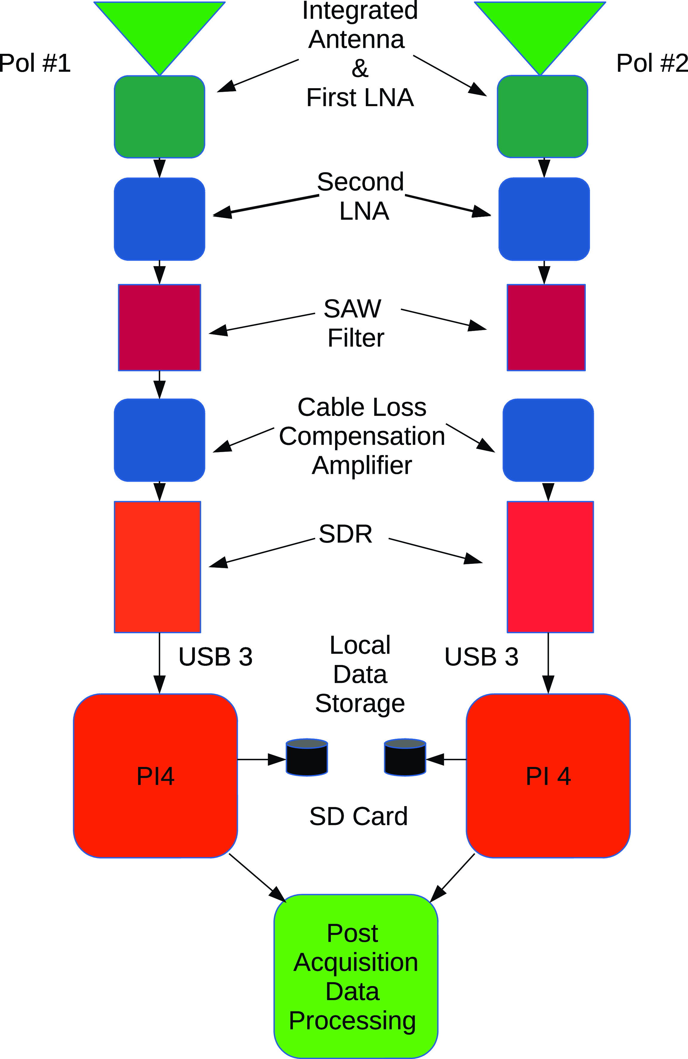
The receiver is a slightly modified version of the ‘Four-leaf clover’ antenna, designed for use at the Molonglo Radio Telescope on its ‘North-South arm’ in the ‘UTMOST-NS’ project (Mandlik et al. 2024). This dual-pole receiver operates in the range 810–860 MHz, using off-the-shelf low-noise amplifiers (LNAs) and surface acoustic wave (SAW) RF filters, available at low cost because of their use in mobile communications (we use a TA1494A SAW chip, centred at 831.5 MHz and with 35 MHz BW). A block diagram of the signal capture, digitisation, and processing chain is shown in Fig. 2.
Block diagram of the signal capture, amplification, digitisation, and processing. The two polarisations are processed separately, via two commerical, off-the-shelf, Software Defined Radios (SDRs).
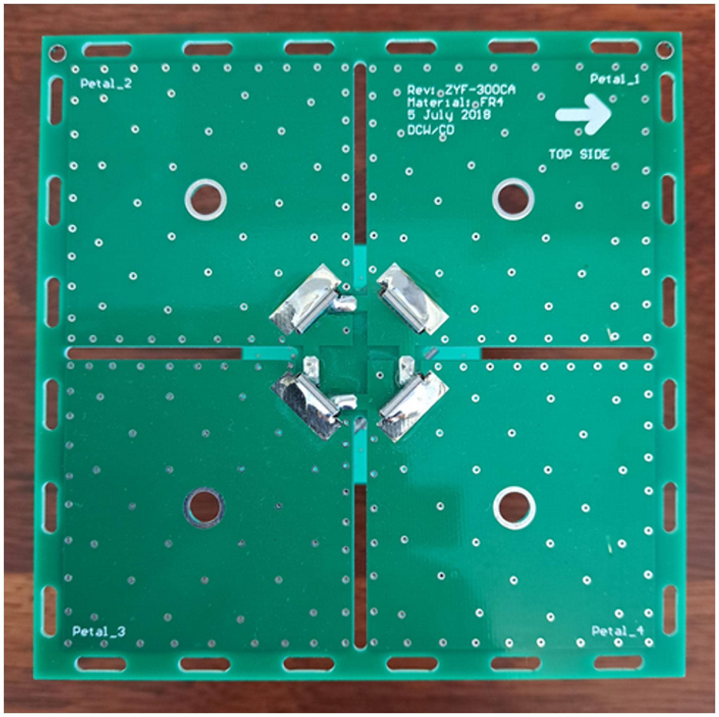
The Four-leaf clover antenna is shown in Figs. 3 and 4. The four patch surfaces of the antenna are coupled pair-wise to provide two polarisations for the RF response. The signal is carried to a baseplate via four stems, constructed as printer circuit boards (PCBs). An amplifier and filter board is attached to the baseplate and is seen with its two polarisation feeds in Fig. 5.
The Four-leaf clover patch antenna, viewed from above. The patch antenna is implemented as a 12.6 × 12.6 cm printed circuit board (PCB). Four square patches of the antenna are seen, with the patches paired to provide response into two orthogonal polarisations.
The Four-leaf clover antenna, in side view. Four stems each include a printed PCB micro-stripline of a matching network, which delivers signal to the baseplate, seen at bottom. The stem design includes slots and grooves along each edge, to provide good mechanical stability when soldered. Stems are 8.8 cm in length.

Amplifier and filter board. This 7.5 × 7.5 cm board attaches to the baseplate of the Four-leaf clover antenna and provides for low-noise amplification (LNA) and impedance matching (50 Ω) to the two coaxial leads. The board is powered via a 5.3 V bias-T through the coaxial leads, drawing approximately 0.35 W.

The signal from the two polarisations are brought via 50 Ω impedance coaxial feeds to two SDR devices, also an off-the-shelf item (SDRPlay RSP2 Pro). These produce 8 MHz 12-bit, unsigned integer, complex sampling of the voltages that are processed and written to a solid-state SD card via the open-source GNU Radio software suite.Footnote a The analogue to digital converter (ADC) is on the MSi2500 chip. The GNU Radio code is run under the real-time option on Raspberry PI4 with 8 GB of storage. The ADC stream is Fast Fourier Transformed (4 000 channels) at 2 000 frames per second, and the complex voltages are squared and decimated to produce 125 channels which are recorded to disc. Importantly, the data acquistion runs unattended. Each Raspberry PI4 is ethernet linked to the observatory’s GPS clock and time server. The PI4 has its own scheduling script that allows independent polarisation data acquisition.
2.3 Digital signal processing
The raw data are converted to filterbank format (van Straten, Demorest, & Oslowski Reference van Straten, Demorest and Oslowski2012) and tools in the psrchive suite (which is widely used in professional radio astronomy) are used to fold the pulsar at its known period using dspsr, to produce archive files, which can be processed with the pdmp to measure the period of the pulsar in each transit observation, both at the Earth (topocentric period) and at the Solar System’s barycenter (barycentric period), that is, pdmp takes into account the position of the observatory in the Earth’s surface and the Earth’s orbit to correct the period to the Solar System barycenter. Archive files are inspected daily, as it may be necessary to remove radio frequency interference (RFI), using tools in the psrchive suite. Generally speaking RFI rarely needs cleaning from the data at Woodchester, because the operating band was chosen carefully in site testing observations during development of the project.
Table 1 shows the digital signal processing software used at Woodchester at each stage in the signal chain.
2.4 Two further 2.4 m systems
The 2.4 m at Woodchester was preceeded by a fully functional demonstrator at the Molonglo Radio Observatory. A 2.4 m satellite dish was also sourced locally at no cost, and a single pole of the UTMOST-NS antenna used as the receiver. The operating frequency was 832 MHz, with a bandwidth of 44 MHz, significantly higher than at Woodchester (8 MHz). We utilised a LimeSDR/Lime SDR Mini for the signal digitisation.Footnote b Vela timing measurements were made on the stronger polarisation (the relevant patch pair on the Four-leaf clover antenna was determined by trial and error). This 2.4 m antenna proved very useful as an independent validator of performance of the 11 × 1.4 m sections of the 1.6 km long North–South arm of the telescope during design, prototyping, construction, and commissioning of the array.
We have also successfully tested the receiver and DSP framework of our design on a fully steerable 2.4 m dish at the CSIRO Division for Radiophysics in Epping, Sydney, Australia, where it had to deal with a hostile RFI environment, due to pervasive mobile handset transmissions, particularly in the range 820-825, 830–835, and 840–845 MHz. We utilised a Tektronix SDR for the signal digitisation. Successful detection and timing of Vela was obtained after careful cleaning of RFI in the daily data.
3. Vela timing data
An example of an observation can be seen in Fig. 6. This is the observation (UTC 2024-04-30) in which a glitch in the Vela pulsar was detected as having taken place since the previous day’s transit observation. The pulse can be seen strongly drifting as a function of time (middle left panel) during the 1 h observation due to the change in the period induced by the glitch.
Software used in the digital signal processing of Vela observations.

A pdmp plot of the integrated pulsar observation during the 1 h transit of UTC 2024-04-30, this being our first observation after the pulsar had glitched. The bottom panel shows the pulsar profile as a function or rotational phase, integrated over time and frequency. We show here the stronger of the two polarisations, which has S/N = 20. The middle panels show the pulse in phase versus time (for 180 sub-integrations of 20 s each) and phase versus frequency. The drift in the pulsar timing due to the glitch is readily apparent in the left panel. The upper panel shows the timing results as a function of dispersion measure (here restricted to a very narrow range around the well-known DM of the pulsar of 67.97 pc cm−3.

Vela timing data in the period January 2024 to July 2024 are shown in Fig. 7. In the upper panel, we show the signal-to-noise, S/N, as a function of Modified Julian Date (MJD), for both polarisations (note that Vela is a highly polarised pulsar). Note that the second (weaker) polarisation was only brought into operation from April 2024. Typically, S/N is between 10 and 20 for the stronger pole, and < 12 for the weaker pole. We only use observations with S/N > 5. Scintilation of the pulsar signal due to the Interstellar Medium is well known to be quite strong for this pulsar (see e.g. Stinebring et al. Reference Stinebring2000 and variation in the signal on time scales of weeks to months, as seen here, is in line with expectation. The middle panel of Fig. 7 shows the difference in the measured barycentric period relative to the first (strong pole) observation, for both poles. The usually steady slow-down of the pulsar is clearly seen as an increasing period with MJD. Note that we have solved for a small offset in the ToAs between the two polarisations of 20 ± 4 μsec and corrected the weaker pole ToAs by this amount. At MJD = 60 430, the data show a sudden decrease in the period, known as a pulsar glitch. Results of a glitch detection algorithm versus MJD are shown in the lower panel of Fig. 7, in which the difference between δ f/f (where f = 1/P0 and P0 is the pulsar period) for each observation relative to the previous transit. The glitch is seen with amplitude of $\approx+2.9 \pm 0.2 \times 10^{-6}$
Hz at around MJD 60430. This is typical for ‘giant glitches’ from Vela (Fuentes, Espinoza, & Reisenegger Reference Fuentes, Espinoza and Reisenegger2019) and demonstrates that glitches of this size are well detectable with this low-cost system. We reported this glitch along with two other facilities as Astronomical Telegrams (Zubieta et al. Reference Zubieta2024; Campbell-Wilson, Flynn, & Bateman Reference Campbell-Wilson, Flynn and Bateman2024, and Palfreyman Reference Palfreyman2024).
$\approx+2.9 \pm 0.2 \times 10^{-6}$
Hz at around MJD 60430. This is typical for ‘giant glitches’ from Vela (Fuentes, Espinoza, & Reisenegger Reference Fuentes, Espinoza and Reisenegger2019) and demonstrates that glitches of this size are well detectable with this low-cost system. We reported this glitch along with two other facilities as Astronomical Telegrams (Zubieta et al. Reference Zubieta2024; Campbell-Wilson, Flynn, & Bateman Reference Campbell-Wilson, Flynn and Bateman2024, and Palfreyman Reference Palfreyman2024).
Vela pulsar timing data in which a glitch was detected, for the period 01/01/2024 to 15/07/2024. The top panel shows Vela S/N in the two measured poles. Only the stronger of the two poles was measured at the start of the timing program, with the weaker pole data processed once dual-pole operation was fully functional. The middle panel shows the change in the pulsar period ΔP0, relative to the period P0 at the start of the program (89.42128194 ms). We correct for a small offset between the ToAs of 20 μsec between the two polarisations, which was measured from 103 observations for which both poles showed S/N > 7. This offset showed no significant change over the observation period. The bottom panel shows the change in consecutive observations of the quantity δf/f, where f = 1/P0. The glitch in Vela is seen as a change in δf/f of order 2.9 ± 0.2 × 10⁻⁶ at MJD 60430.366.

An interesting feature in the ‘glitch detector’ plot (lower panel of Fig. 7 is clear quantisation in the pulse ToAs, seen as discrete values in the quantity Δ(δ f/f. Approximately 10 discreet values are present in the data, with a separation of $\approx+2 \times 10^{-7}$
in units relative to the pulsar frequency, or
$\approx+2 \times 10^{-7}$
in units relative to the pulsar frequency, or $\approx+18 $
ns in absolute units. The two most likely sources of this digital jitter in the timing, which has the same amplitude on each SDR (each pole has an independently operated SDR, cf. Fig. 2). These two sources are firstly, the SDR clock signal (which is a 24 MHz crystal output) and second, the MSi2500 ADC chip doing the analogue to digital conversion. We have ruled out the SDR clock signal using a high-quality reference signal at 24.0 MHz, measuring the clock jitter to be <2.5 ns. We note that the SDR oscillator and the USB discipline are provided by a 24 MHz TCXO (temperature controlled crystal oscillator). We suspect the digital jitter in the pulsar timing arises in the ADC chip, but unfortunately retrieving an ADC chip for testing would destroy the SDR, so this has not been carried out. Instead, we are in the process of upgrading the discipline level to a Rubidium (Rb) standard. Two approaches are being examined: first, a synthesiser based on a 24 MHz VCXO (voltage controlled crystal oscillator) and second, direct digital synthesis (DDS) for the 24 MHz source link to the 10 MHz reference.
$\approx+18 $
ns in absolute units. The two most likely sources of this digital jitter in the timing, which has the same amplitude on each SDR (each pole has an independently operated SDR, cf. Fig. 2). These two sources are firstly, the SDR clock signal (which is a 24 MHz crystal output) and second, the MSi2500 ADC chip doing the analogue to digital conversion. We have ruled out the SDR clock signal using a high-quality reference signal at 24.0 MHz, measuring the clock jitter to be <2.5 ns. We note that the SDR oscillator and the USB discipline are provided by a 24 MHz TCXO (temperature controlled crystal oscillator). We suspect the digital jitter in the pulsar timing arises in the ADC chip, but unfortunately retrieving an ADC chip for testing would destroy the SDR, so this has not been carried out. Instead, we are in the process of upgrading the discipline level to a Rubidium (Rb) standard. Two approaches are being examined: first, a synthesiser based on a 24 MHz VCXO (voltage controlled crystal oscillator) and second, direct digital synthesis (DDS) for the 24 MHz source link to the 10 MHz reference.
4. Cost model and potential improvements
The 2.4 m telescope presented here was built at modest cost, mostly through reuse of existing components available at no cost from other projects, access to a free disused satellite dish, readily available hardware (retired laptops, Raspberry Pis), and 2 × SDR digitisation devices. Total outlay was less than USD 200.
The 2.4 m presently operates at a bandwidth of 8 MHz, and requires of order 1 h to achieve S/N > 10. The obvious improvement is to increase the system bandwidth – for example, dual-pole, 50 MHz bandwidth SDR cards are commercially available for under USD 1000. In principle, system sensitivity can be improved by of order the square root of the ratio of the bandwidths – however, this has to be offset by the changing pulse profile and flux density of the pulsar as a function of frequency, as well as the need to find a region of continuous spectrum as free of RFI as possible. These three factors need to be carefully weighed. For the 8 MHz of bandwidth settled on for this project, we found that 820 MHz was a very effective region to work at, under the three constraints above.
Unfortunately, there are no other Southern Hemisphere sources that are readily detectable without a substantial improvement in sensitivity. Increasing the bandwidth to, for example, 50 MHz would improve the Vela timing substantially but is unlikely to give access to further pulsars. Increasing the dish diameter yields S/N improvements in proportion to the dish area, but dishes larger than the 2.4 m at Woodchester bring other challenges, such as wind load and heavier mounts, and may become too unwieldy for, for example, projects demonstrating pulsar timing for high school or STEM students who would like to build and operate all parts of the system.
5. Summary and conclusions
We demonstrate a low-cost radio telescope using a 2.4 m satellite dish, an inexpensive dual-pole antenna based on printed circuit boards (PCB) and commodity-off-the-shelf (COTS) filters and RF digitiser SDR devices. Total outlay for the telescope was under USD 200. We make use of open-source, professional radio acquisition and pulsar processing software to successfully monitor the Southern Hemisphere pulsar J0835−4510 (aka the Vela pulsar) at Woodchester Observatory in South Australia. Woodchester operates at 820 MHz with 8 MHz of bandwidth, performing 1 h transit observations daily. The system successfully detected a ‘glitch’ in the Vela pulsar in real time. Woodchester represents a good balance of bandwidth, observation time, and cost to achieve scientifically interesting results for amateur radio astronomy and/or STEM outreach projects.
Data Availability Statement
Data from this project will be made available upon reasonable request to the authors.


 Open access