


1. Introduction
In today’s rapidly evolving business laGndscape, continuous methodology development is essential for organisational success. Static approaches quickly become obsolete as market conditions shift, technologies advance, and customer expectations change. Companies that fail to adapt risk losing competitive advantage and relevance. Continuously refining methodologies enables organizations to respond effectively to change and foster innovation. This iterative approach enhances efficiency and improves quality. It also cultivates a learning culture where employees feel engaged and valued, contributing to frontline insights that drive practical improvements.
Treating methodology development as an ongoing commitment—rather than a one-time initiative—positions companies to thrive amid uncertainty. It enables agility, supports talent retention, and creates sustainable competitive advantages that directly impact profitability and long-term viability in an increasingly demanding market. A robust methodology also allows companies to scale efficiently and innovate strategically, rather than relying on improvisation. This paper will highlight and summarises several minor projects within Knowledge-Based Engineering (KBE), Design Automation (DA), and Visual Modelling Environment (Graph based design) that have been conducted in a company environment. With the use of digital twins, development cycle time can be reduced by 10-75% and unplanned maintenance downtime reduction by about 40%, as stated by the AIAA Digital Engineering Integration Committee (2020).
1.1. Knowledge Based Engineering (KBE)
Modifying and tailoring products to various versions and setups are, according to Reference CederfeldtCederfeldt (2007), routine activities in the industry. These tasks, when performed frequently, can result in significant time spent on repetitive and monotonous work. Reference CederfeldtCederfeldt (2007) suggests that by minimising this, engineers can concentrate more on genuine design challenges, such as addressing problems that demand expertise and innovation. He proposes that one method to reduce repetitive tasks for design engineers is to convert manual processes into automated ones, which can be achieved using KBE. Overall MOKA methodology (Reference StokesStokes, 2001) is used in all the work related to geometry and the generation of geometrical models by Effective Parameterization (Reference MunjuluryMunjulury, 2017), the implementation of KBE in the design of an aircraft by Reference Munjulury, Staack, Berry and KrusMunjulury et al. (2016) is utilised as a starting point to the initial work presented in the Section 3.
Reference Chapman and PinfoldChapman and Pinfold (2001) describe the objective of the KBE methodology as “…to capture the best design practices and engineering expertise into a corporate knowledge database”. They define the purpose of KBE as collecting, storing, and processing product information to enable the automation of some or all elements of the engineering design process. Reference Chapman and PinfoldChapman and Pinfold (2001) provide several industry examples where the use of KBE has resulted in substantial time savings in designing and redesigning, as well as navigating through various design cycle activities that influence design requirements. One such example is Textron Aerostructures, which saved 73% of design time by implementing a tooling design application.
1.2. Design Automation (DA)
Reference CederfeldtCederfeldt (2007) describes knowledge transfer mechanisms in DA systems, identifying three key participants: the developer (who encodes expertise), the computational system (which executes programmed logic), and the end-user (who applies outputs to practical design tasks). This framework illustrates how domain knowledge flows through technological systems, transforming from expert understanding into actionable design guidance. Reference Amadori, Tarkian, Ölvander and KrusAmadori et al., (2012) build on this concept by demonstrating how KBE effectively integrates with advanced Computer-Aided Design (CAD) modelling. They establish that by systematically capturing rules and relations during the modelling process, knowledge becomes embedded within digital models, enabling designers to generate variations, produce repetitive geometry, and access supportive information throughout their work. Furthermore, Reference Amadori, Tarkian, Ölvander and KrusAmadori et al. (2012) characterize model flexibility through two dimensions. The morphological level describes geometric transformation capabilities, allowing designers to modify dimensions and shapes while maintaining structural integrity. The topological level addresses spatial relationships and object positioning, encompassing instantiations such as adding, removing, or substituting components at specified locations.
Reference Cederfeldt and SunnersjöCederfeldt and Sunnersjö (2003) emphasize the importance of systematic approaches when developing CAD models for design variability. They identify three distinct modelling strategies suited to different complexity requirements. Dimension-driven parts represent the simplest approach, using parameters to control geometric properties such as length and height. Generic parts with variable topology offer greater sophistication, incorporating feature activation and deactivation mechanisms that allow topology changes beyond simple dimensional adjustment. Modular parts provide a third approach, decomposing complex assemblies into smaller standardized components retrieved from libraries and parametrically configured for specific applications. Reference CederfeldtCederfeldt (2004) classifies design variables by information type and source. Information type divides into geometric interdependencies within CAD environments and computational mechanisms linking design parameters. Information sources comprise established knowledge—including industry standards, technical handbooks, and best practices—and organizational knowledge encompassing experience-based guidelines and proprietary technical findings. This classification system helps practitioners understand how different knowledge types should be captured, stored, and integrated within automated design environments, supporting more systematic DA implementation across organizational contexts.
1.3. Visual modelling environment
Nowadays, most of the available CAD tools have several supported languages/ Application Programming Interface (APIs) that help with the DA. The current notable Graphical programming environments that are available CATIA Visual Scripting by Dassault Systèmes, Dynamo by Autodesk and Grasshopper for Rhino. Visual Programming Languages (VPLs) and Textual Programming Languages (TPLs) are the two main types of languages used in generative design in a design process (Reference Leitão, Santos and LopesLeitão et al., 2012). TPLs are representative of languages like C, C#, Python, or Java employ text-based coding. Because they enable users to alter coding elements graphically rather than textually, VPLs, often referred to as diagrammatic programming languages in CAD software (Reference Celani and VazCelani & Vaz, 2012). These visual scripting tools reduce the need to write several lines of code to perform a design while increase the speed to do the changes could be as easy as moving a scroller bar. The work presented in this paper employed Visual Scripting in 3DExperinence for VPL and Excel’s VBA for TPL.
1.4. Standardisation
The use of standards guarantees the digital thread’s uniformity and continuation (Reference Hällqvist, Munjulury, Braun, Eek and KrusHällqvist et al., 2022); the International Organization for Standardization (ISO) emphasizes that using common and defined formats for the integration of digital artifacts is crucial to ensuring interoperability across collaborative organizations (ISO, 2000). Reference Munjulury, Staack, Berry and KrusMunjulury et al. (2016) demonstrated the use of XML as a centralized database to exchange the information between several disciplines in a conceptual design scenario. Furthermore, the database was connected to Common Language for Aircraft Design - CPACS (Reference Alder, Moerland and JepsenAlder et al, 2020), to enhance the interdisciplinary collaboration and enable automated simulation workflows. While CPACS is used for aircraft design, System Structure and Parameterization (SSP) could be used for complete systems including, Functional Mock-up Interfaces & Functional Mock-up Units and related parameters for components can be exchanged between tools, an example is presented by Reference Hällqvist, Munjulury, Braun, Eek and KrusHällqvist et al. (2022) for an environmental cooling system. After the creation of the detailed geometry, Model-Based Definition (MBD) is extensively used in most of OEM’s enabling the use of same geometrical model from Design to Production (Reference Roth, Aderiani, Morse, Wärmefjord and SöderbergRoth et al., 2025). Ultimately, the objective is to finalize the digital thread by integrating the Quality Information Framework (QIF) standard, thereby ensuring a smooth geometry assurance process (Reference Roth, Aderiani, Morse, Wärmefjord and SöderbergRoth et al., 2025).
1.5. Purpose
The purpose of these theses was to examine how KBE, DA and other newer techniques can be used as support in the product development process, with the generated systems and parts incorporating Saab ’s generic design rules, dimensioning guidelines from different departments, and manufacturing knowledge to facilitate faster and more stringent workflows. The applications must be simple to use and clearly present what information has been processed automatically, so that design engineers can confidently embrace them without doubt about which rules have been activated in automatically generated articles, allowing them to trust the system as genuinely helpful. By successfully building knowledge into a system or component through DA, this would serve as a first proof of concept for implementing e.g., KBE and standardisations in Saab ’s product development, ultimately reducing user errors and lead times in conceptual design creation, while freeing design engineers from tedious routine modelling to focus on ensuring quality in early concept development.
2. Methodology
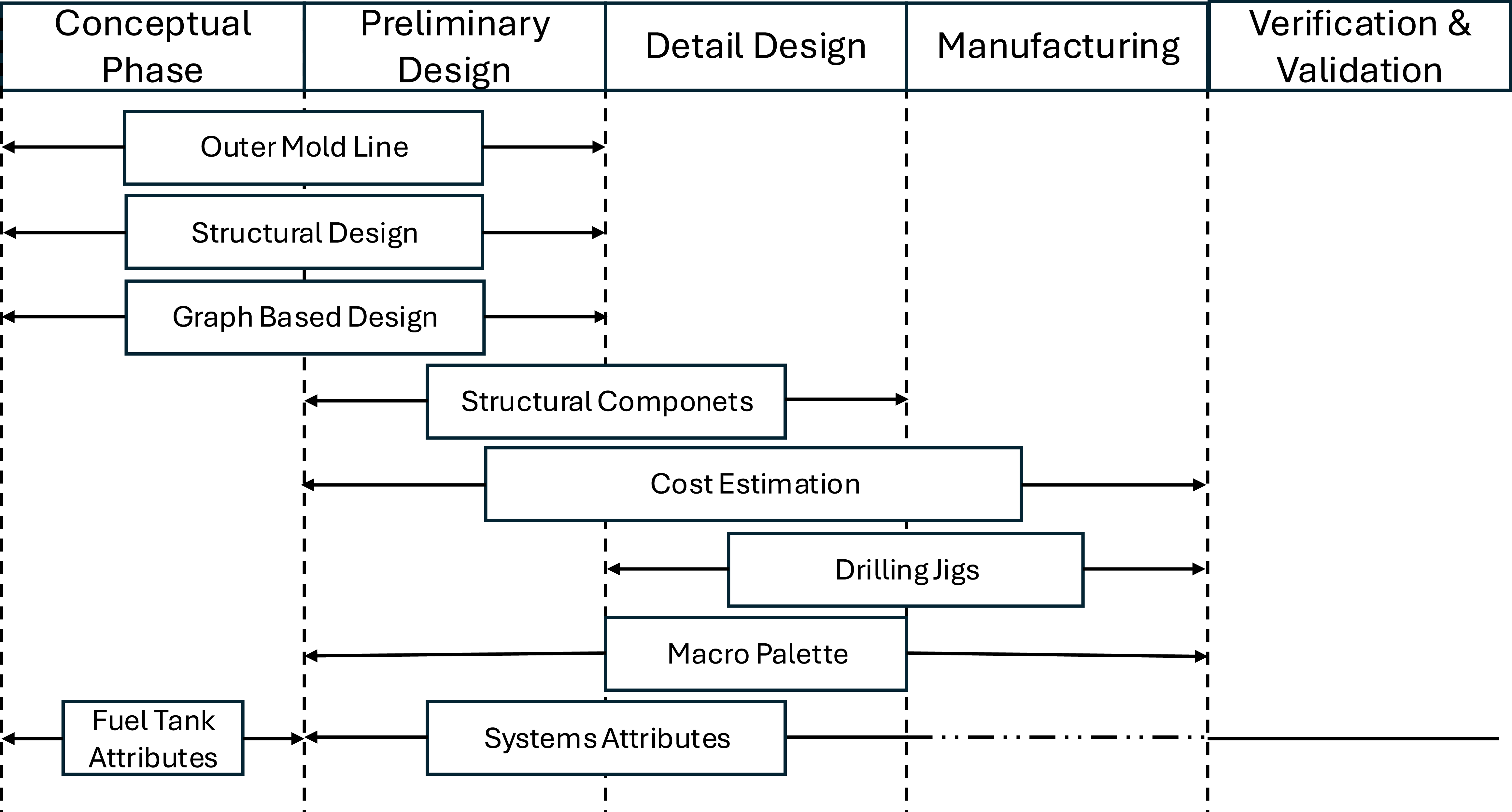
The results from several smaller pilot projects are presented in this paper as shown in Figure 1, these projects have been conducted over the last years. All of them have had the same focus, to further develop the methodology, often by using KBE, DA and standardisation, or supporting the use. In a holistic methodology view it can be seen as applying a Minimum Viable Product (MVP) approach in a methodology development. Creating modules that singlehandedly can give functionality and create value of its own and at the same time build the over-all methodology.
Overview of knowledge-based engineering initiatives implementation
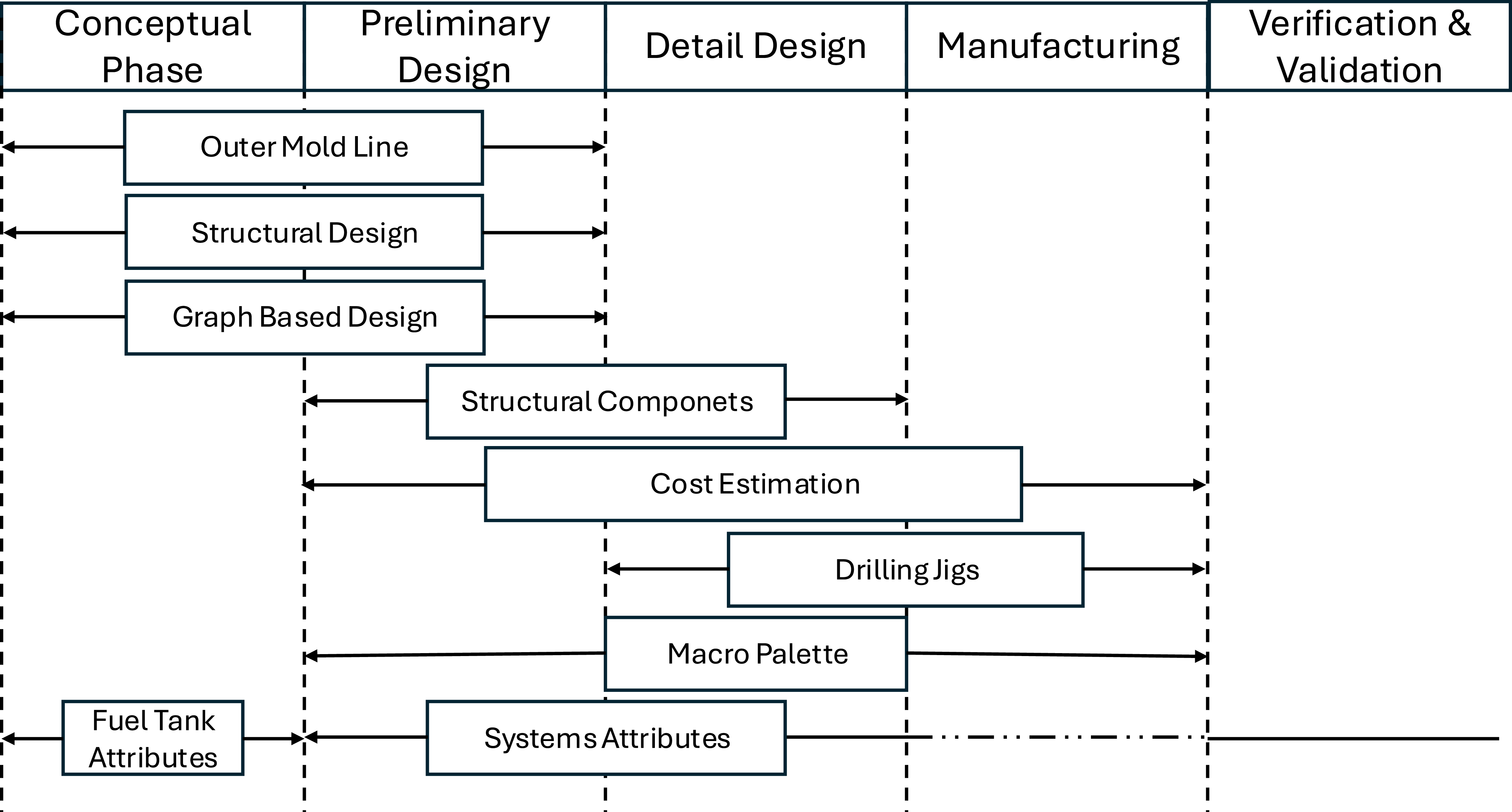
Figure 1 Long description
The flowchart illustrates the stages of a design process, including conceptual phase, preliminary design, detail design, manufacturing, and verification and validation. The process begins with the conceptual phase, which includes outer mold line, structural design, and graph-based design. These steps lead into the preliminary design phase, which involves structural components. The preliminary design phase then flows into the detail design phase, where cost estimation, drilling jigs, and macro palette are considered. The detail design phase transitions into the manufacturing phase, which subsequently leads to the verification and validation phase. Throughout the process, systems attributes and fuel tank attributes are considered, influencing the design and validation steps.
All the different projects have followed the same structure and methodology. Each project spanned an approximate duration of six months and was undertaken as a master’s thesis, involving one to two students under the supervision of company employees. The overall structure involved interviews, literature study (both internal documents and public material). The project outcomes have been transitioned from a sandbox environment to implementation within the intended operational context. The aim has been to find repetitive tasks related to design or to connect more disciplines to give the designer better information in the design process. For details of the individual methodologies and functional descriptions, please refer to the corresponding projects presented in Section 3. Unless explicitly stated otherwise, the reduction in time is measured against the manual design of the respective geometries discussed in this paper.
3. Results
Over the course of several years, various KBE thesis have been initiated to test the capabilities of the methods and tools, as well as to implementing some of the outcomes of the theses. The following section presents all the results obtained from the theses, as mentioned in Figure 1.
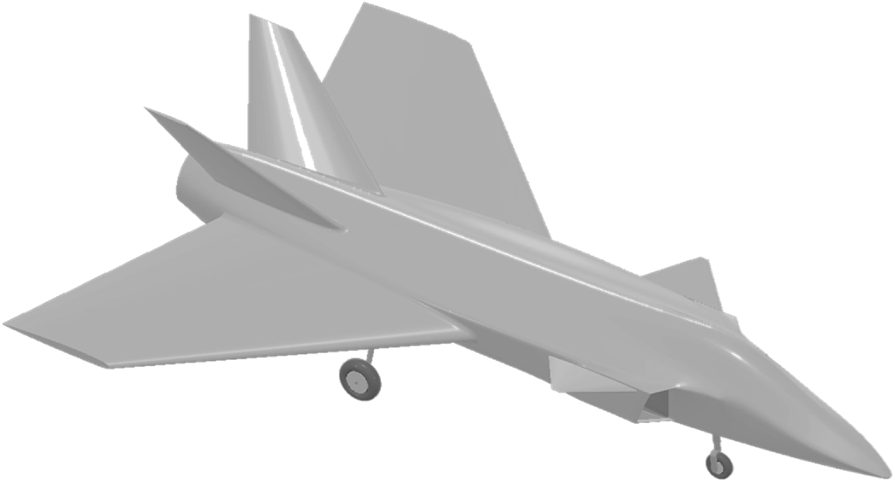
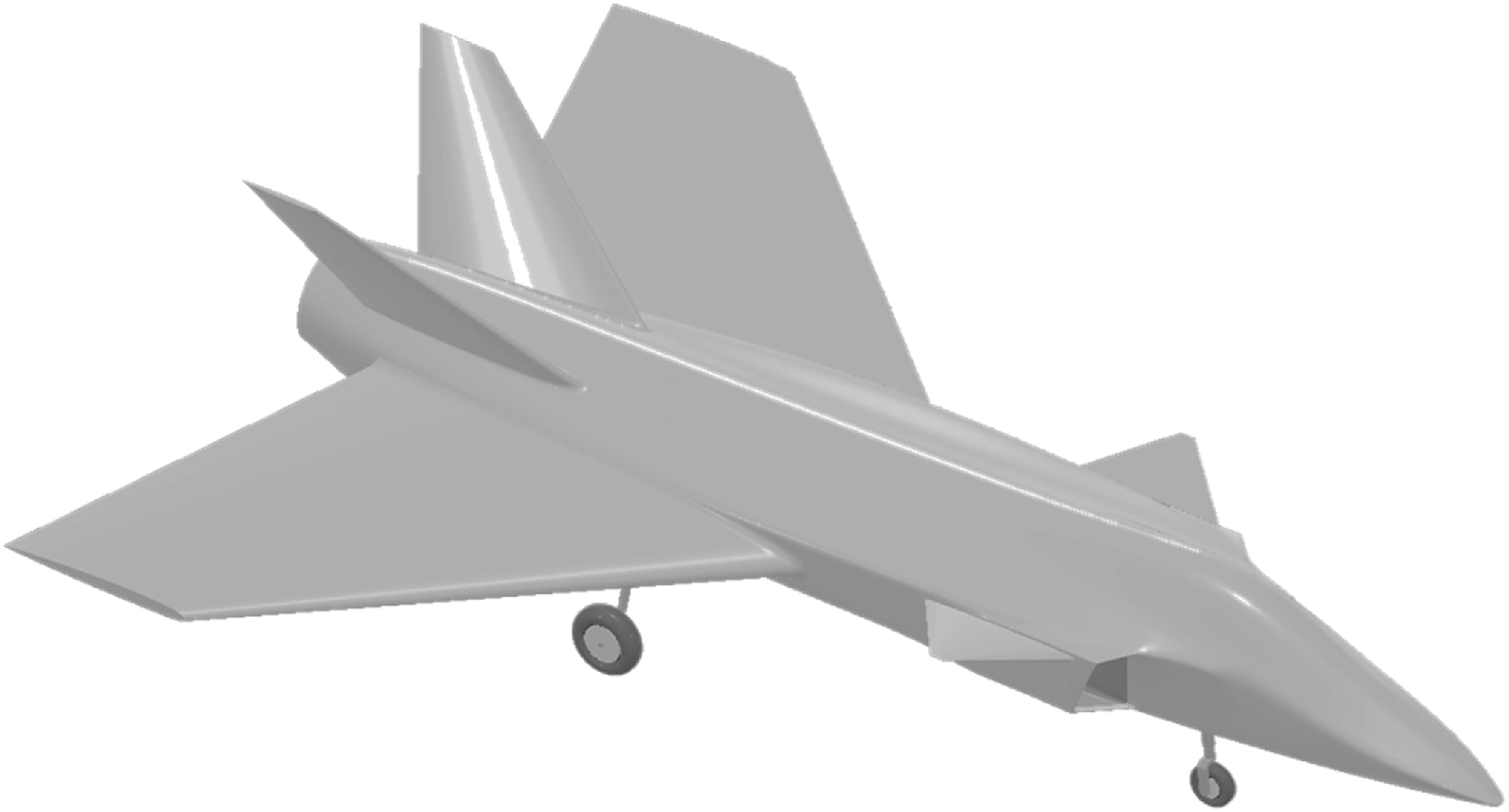
Outer mold line (OML) of complete aircraft
3.1. Outer Mold Line (OML) and structural design
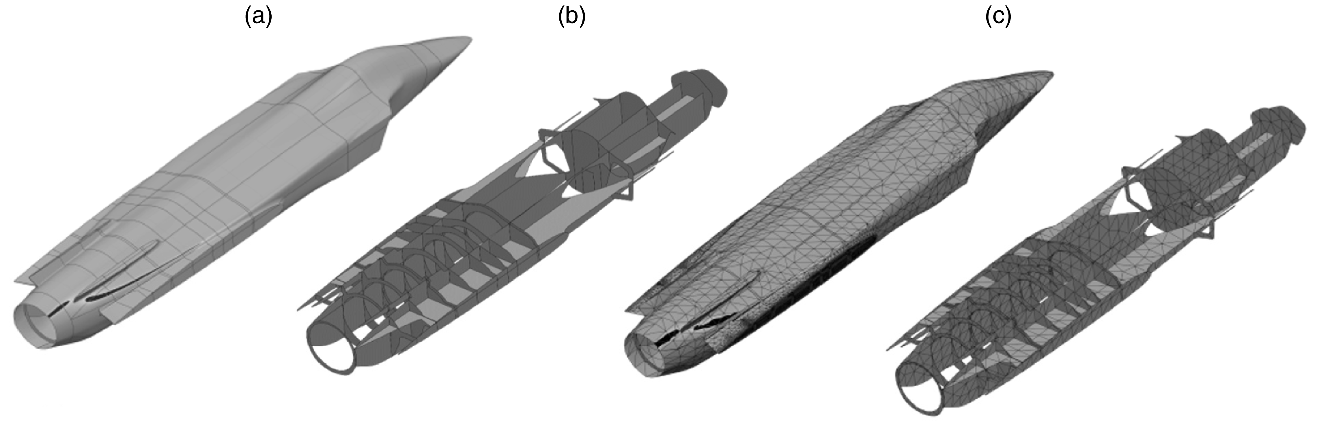
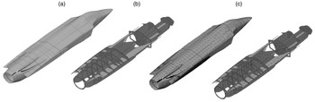
The initial implementation of KBE with 3DExperience began with a small project. The aim was to understand the overall workflow and to observe the complete process from design to analysis that paved the way for the projects mentioned in Sections 3.1 and 3.2. The goal was to integrate Geometry, Finite Element Method (FEM), and Aerodynamics, and complete the loop with an optimisation framework. The first OML was created, and KBE methods were used to automate the wing structure. Unlike conventional fuselage design, the fuselage geometry was developed using subdivision surfaces to achieve better surface continuity (Figure 2). A new approach was developed to ensure that the fuselage geometry is parametric while also integrating all the subdivision surfaces along with the other lifting surfaces. The fuselage geometry developed in this initial project was later utilised in the creation of the structural geometry, removing all the lifting surface (Figure 3(a)).
The structural geometry needs to be automated to swiftly create a new structure and evaluate several concepts to obtain the best possible design. The thickness of each section of a rib or spar are evaluated to determine the best possible structural layout. This work investigates the rapid exploration of design space to identify a suitable foundation for a new concept, including a synchronization between a Structural Layout Model (SLM) (Figure 3(b)) and a Global Finite Element Model (G-FEM) (Figure 3(c)). First, the fuselage SLM is created using the KBE and DA techniques; a script is later used on this model, which generates a G-FEM model, resulting in faster concept generation and design iterations during the development process. The result enabled a faster design iteration to the existing workflow (Reference Brånäs and EnderbyBrånäs & Enderby, 2022).
(a) OML (b) SLM (c) G-FEM of fuselage and structure
3.2. Visual programming/scripting
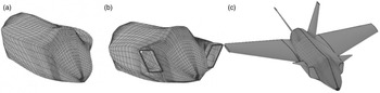
Visual Scripting (VS) significantly enhances the design process, featuring an intuitive and practical interface, VS provides functionalities that lead to a general reduction in the time required for various repetitive tasks in a design process (Reference BarnekowBarnekow, 2024). The initial goal was to observe the capabilities of CATIA Visual Scripting and use it to produce the OML and integrate air intakes on to the aircraft. Some of the limitations were solved in the later releases that helped to recreate a complete OML and structure of the aircraft using VS. Firstly, the use of Imagine and Shape app operations to ensure compete fuselage generation. The work presented by Reference BarnekowBarnekow (2024), shows the generation of initial fuselage using Imagine and shape (Figure 4(a)), later the inlet design as presented by Reference Blixt and SchönningBlixt and Schönning (2023) was used to instantiate the desired inlets needed for the fuselage. Reference BarnekowBarnekow (2024) also presents several examples of aircrafts generated by using VS.
Geometry generated using visual scripting
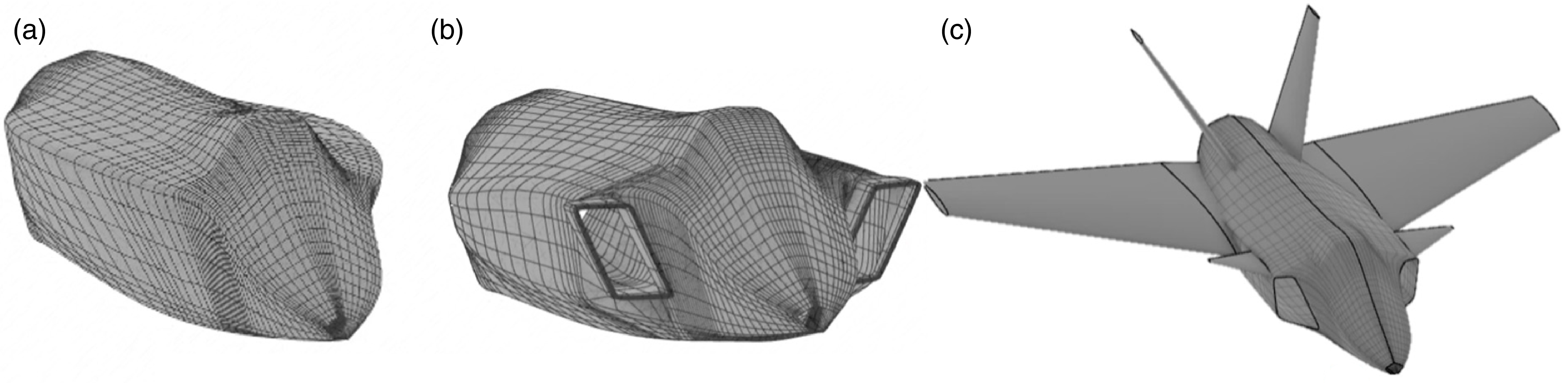
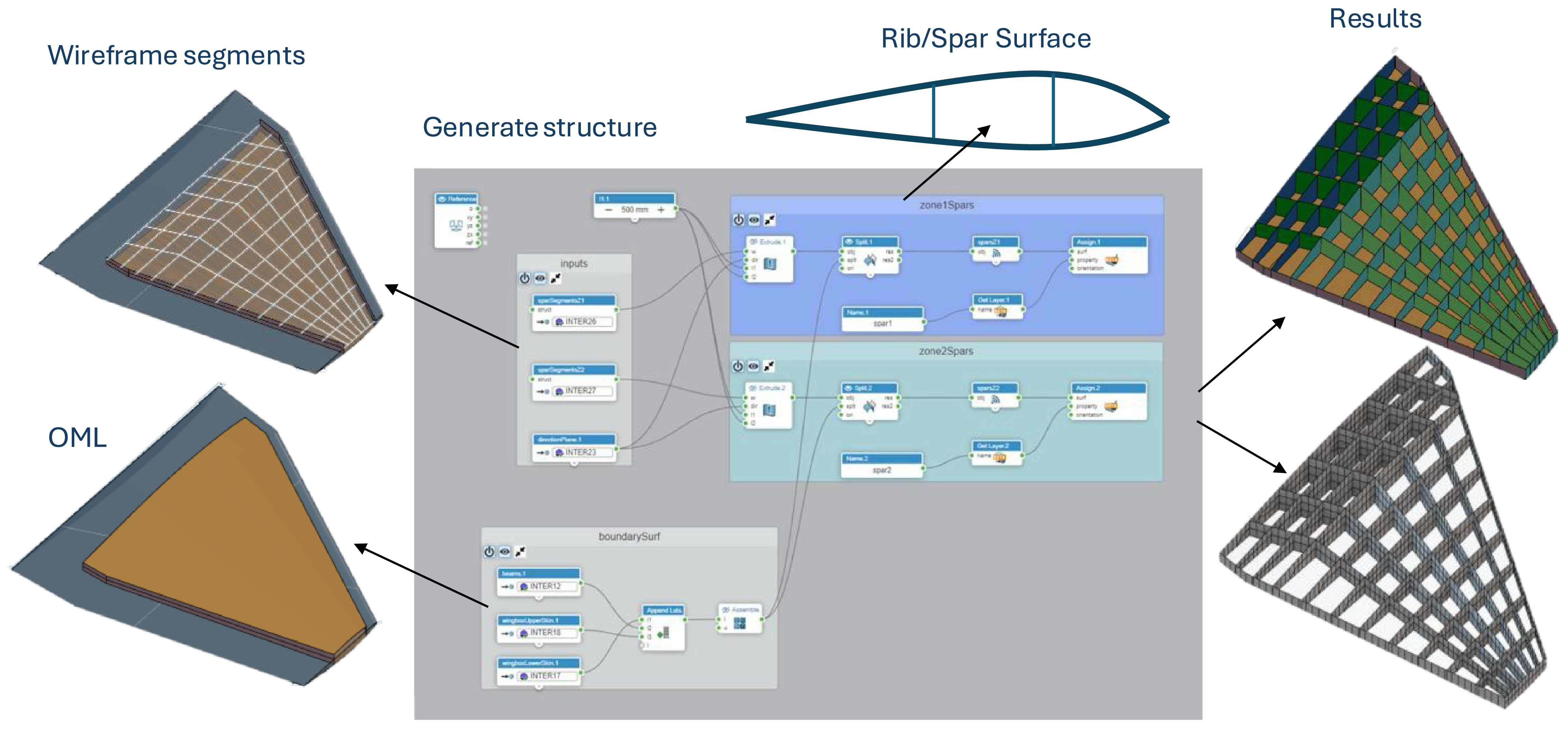
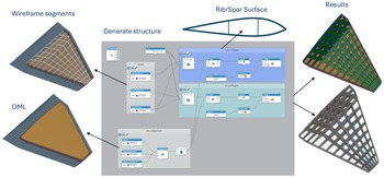
Reference Larsson and MånströmLarsson and Månström (2025) continued this work to generate a complete aircraft structure and integrate it with the geometry by creating a simplified schematic framework from a pre-existing aircraft surface model (Figure 4). Templates were instantiated using 3DExperience Visual Scripting and Enterprise Knowledge Language (EKL), and the resulting geometry was imported into 3DExperience Concept Structure Engineering for subsequent meshing and analysis (Figure 5). Although geometry generation was achieved through a repeatable automated process, limitations within the meshing tool hindered the consistent alignment of intersecting edges and the sharing of mesh nodes. The present study demonstrates the feasibility of automated transitions from geometry generation to analysis using graph-based logic, while also highlighting the necessity for consistent data handling and predefined meshing rules. Future research should prioritize the implementation of rule-based meshing and the enhancement of information sharing to facilitate fully automated workflows.
Wing structure workflow using visual scripting
3.3. Structural design development
The following section presents the works involved in the development of the geometry from design to production deployment.
3.3.1. Structural component
The modern structure of an aircraft is made of machined articles and therefor it has a big potential for the project to help designers with automation. The aim of this project was to see if it was possible to generate geometry for machined articles. A normal machined article has common features such as flanges, stiffener, holes, pockets etc. The project was divided into two different parts. The first part was to create the basic geometry, and the second part was to support holes and fastener configurations to the article. Both these are a result of several similar and repetitive tasks which make them suitable for automation.
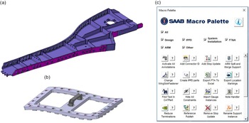
The design must meet the requirements of various disciplines and departments, each contributing their unique input. Consequently, the designer must adhere to a wide range of rules and guidelines to ensure the component aligns with company standards. Furthermore, updating the design across multiple iterations can be repetitive and time-intensive, with designers often receiving minimal support during the modelling process. As a result, the geometry model and the process of designing geometry needed to be slightly changed and several templates were developed that can be instantiated into the skeleton structure. For managing the hole and fasteners a toolbox was developed to help the designers with automation both for designing and redesigning (Reference Agnvall and HjelmqwistAgnvall & Hjelmqwist, 2018) as shown in Figure 6 (a).
a) Structural article b) drilling jig c) macro palette
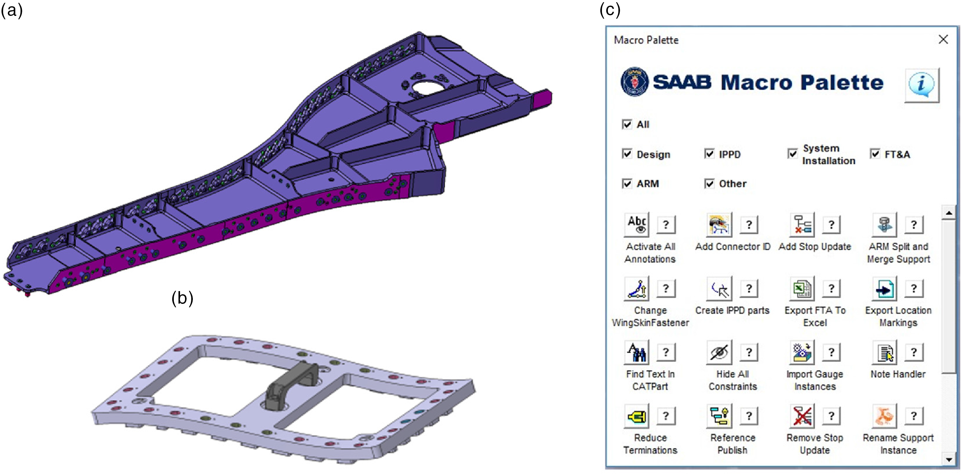
Figure 6 Long description
Panel A: A 3D model of a structural article, likely an aircraft component, with detailed internal and external features. Panel B: A 3D model of a drilling jig, used for precise drilling operations, showing its structural design and components. Panel C: A screenshot of a macro palette interface from SAAB, displaying various design and installation options and tools.
3.3.2. Drilling jigs
In the production of aircraft, there is a significant requirement for the utilisation of manufacturing tools to ensure the productivity and precision of aircraft components. An example of a commonly used jig is a drilling jig, which serves the purpose of securing the workpiece and guiding the drilling operation to achieve the desired hole pattern. At Saab Aeronautics, drilling jigs are modelled in CATIA through manual processes, which often results in a considerable amount of repetitive work for the design engineers responsible for modelling these jigs. This project focused on the application of KBE and DA to reduce repetitive and time-consuming tasks for design engineers creating drilling jigs in CATIA, as well as to implement a standardised modelling process. The primary objective of the thesis is to demonstrate the potential of KBE and DA in a design process to enhance the efficiency and standardisation of modelling activities. This is accomplished through the development of a design tool in Visual Basic for Applications, which guides design engineers and automates modelling actions. The design tool serves as a proof-of-concept, illustrating the possibilities for time and effort savings in the design process of drilling jigs (Reference Rydberg and SchmelingRydberg & Schmeling, 2019) at Saab, see Figure 6 (b). The results show that the time is reduced from 8 hours to 1 hour compared with manually designing the jig, and the quality of the model itself is considerably better.
3.3.3. Automatic development of the In Process Part Definition (IPPD)
The design process for IPPD (In Process Part Definition) is where the article deigned in CATIA becomes manufacturable and prepared for assembly. The IPPD consist of a design article and the Assembly Requirement Model (ARM) and is defined as a MBD object. The process for creating the IPPD can be seen as the interface between design and production. The work started by conducted interviews to identify tasks that have a strong potential for automation. The IPPD development comprises of numerous stages; the tasks identified as monotonous or inefficient were chosen for additional study. Some of the tasks already had macro support, and additional macros were created for the identified tasks to enable a more automated IPPD development. In the end, the new macros showed a great potential in comparison with old macros (Reference Pettersson and MagnussonPettersson & Magnusson, 2019).
3.4. Macro palette
A preliminary investigation from interviews revealed that the primary impediment to the increased adoption of DA was not a scarcity of KBE applications, instead, the lack of effective information dissemination and user-friendly interfaces was identified as the key barrier. The primary objective of this project was to develop a graphical tool designed to facilitate the utilisation of various pre-existing modules by design engineers. Consequently, the project focused on addressing these issues by developing a graphical user interface that provides convenient access to KBE applications. The main outcome of this project is the development of a GUI named the “Macro Palette” as shown in Figure 6 (c) and annotated with the names of the constituent macros. This interface is constructed using user forms and code within the Visual Basic Editor for CATIA. Design engineers can access the Macro Palette directly from CATIA and locate the appropriate KBE applications using various filtering options. The Macro Palette is designed to be customisable for specific work situations or projects, with an automatic update feature that streamlines the maintenance process (Reference Westerlund and WinqvistWesterlund & Winqvist, 2019).
3.5. Systems attributes
The work presented by Reference Hällqvist, Munjulury, Braun, Eek and KrusHällqvist et al. (2022) has been enhanced with a semi-automated framework that connects CATIA V5 geometric models of coolant distribution systems to system-simulation models using the Functional Mock-up Interface (FMI) and SSP standards with pressure-loss coefficient estimation with friction. The approach (Reference DuringDuring, 2023) enables deterministic extraction of simulation parameters, including pressure-loss coefficients, lengths, insulation coverage, and inlet coordinates. Pressure-loss estimation uses deflection-angle analysis to detect bends and applies correction factors for Reynolds number, bend-to-bend interaction, outlet length, and friction. Validation against literature data shows mean error of only a few percent. A user interface separately maps CAD parts to simulation components, allowing flexible aggregation without modifying the geometry. The workflow is integrated into an MBSE development process.
A data-driven methodology for modelling aircraft fuel systems by utilizing geometric data is investigated (Reference SandbergSandberg, 2025). The parameters are exported in both SSP 1.0 (Modelica Association, 2019) and SSP 2.0 (Modelica Association, 2024) formats, emphasizing a shift towards the more recent SSP 2.0 standard. The parameter data undergoes validation and is then utilized in Python to train machine learning models aimed at estimating physical characteristics such as the Center of gravity (CG) and volume. The resulting SSV files, which contain the results from the trained models, are essential outputs for subsequent applications, utilizing Modelica extensions, which guarantee compatibility with the ThermoFluid library and within Dymola. Also, SRMD (Simulation Resource Meta-Data) files, used to store simulation metadata and ensure traceability, are used to document metadata and simulation traceability, adhering to the SSP Traceability specification. This research contributes to the wider application of standardized formats and enhances the development of system-level simulation methods in accordance with Modelica Association standards.
3.6. Cost estimation
A challenge in product development lies in the early estimation of production costs and in the capacity to compare two or more machined components. The aim of this project was to determine whether early estimations could be employed in a selection process for an optimal design. During the initial phases of the design process, a significant portion of the manufacturing costs are determined. However, when designing a component, the costs associated with producing specific features are often unclear. By integrating DA and KBE into the design workflow, design engineers can gain insights into the necessary actions to mitigate costs and reduce overall manufacturing expenses.
A Feature-Based Costing (FBC) method is employed to create the cost estimation process (Reference Molin and VänglundMolin & Vänglund, 2020). FBC leverages the data from features by utilising the distinctive attributes. By applying a standardised framework, using a library of templates as building blocks for the CAD model (outlined in Section 3.3). The library of templates in this thesis work is stiffener, flange, holes, pockets (including weight reductions), pocket analysis, and tree structure. Essential performance metrics for these manufacturing processes come from actual manufacturing data connected to the tools and machines. The model information and performance are incorporated in the cost calculations. The result of the project was macro that helps the designer in a way, so it is possible to distinguish variation in cost and time by adjusting the design of a model. Due to time limitations the application was only developed for a 5-axis CNC machine.
4. Conclusions
Several smaller proof-of-concept projects have been carried out to develop capabilities that can be employed in future applications. Each of these projects shared a common objective: to provide designers with enhanced support in their day-to-day work. A key finding from these endeavours is the importance of maintaining consistency throughout the development process, specifically with respect to standardised working procedures, naming conventions, and uniform methods for constructing geometric models. Artificial intelligence has not been employed in these projects; however, it is expected to become a valuable component in future work.
Methodology development should be regarded as a continuous activity rather than a one-off effort, because markets are constantly evolving and demand that companies continually assess and adapt their approaches. Building upon an existing methodology is a systematic way to refine, extend and adapt it while keeping the proven core principles intact. It involves identifying missing practices, removing redundant steps and spotting opportunities to simplify or enrich the approach. These opportunities facilitate the ongoing refinement and development of existing methodologies. By embedding organizational knowledge into design systems and freeing engineers from repetitive tasks, Saab can create an environment where design expertise focuses on innovation, quality, and strategic problem-solving—essential capabilities for long-term competitiveness.
Acknowledgement
The authors would like to thank the students that conducted the work and Saab for giving the possibility to publish.

 Open access

