


Introduction
Over the last 50 years, lasers have been developing rapidly, and with this development, more applications emerge. Currently, there are petawatt lasers are firing at a rate of the order 1 Hz (Danson et al., Reference Danson, Hillier, Hopps and Neely2015), and terawatt lasers are approaching kHz (Perry and Mourou, Reference Perry and Mourou1994). This creates a lot of options for new science and technology but also presents some problems to be overcome. One of these problems is how to have a high intensity contrast ratio (ICR) at these high repetition rates. The ICR is the ratio between the intensity of the main pulse and the prepulse (energy that is delivered to the target before the main pulse) and can be measured for different amounts of time before. A poor ICR can be due to prepulses generated during amplification or amplified spontaneous emission (ASE) from the amplifier medium. Ultra-short pulses normally have a pulse pedestal (Doumy et al., Reference Doumy, Quéré, Gobert, Perdrix, Martin, Audebert, Gauthier, Geindre and Wittmann2004) that starts on the order of picoseconds before the main pulse, which although several orders of magnitude smaller than the main pulse, due to the high intensities being achieved still cause severe perturbations to the target.
The main perturbation to the target by the prepulse is via ionization. Field ionization (Keldysh, Reference Keldysh1965) occurs an intensity of the order  $10^{14}\, {\rm W/cm}^{2}$ (Kapteyn et al., Reference Kapteyn, Murnane, White, Szoke and Falcone1991), and two photon ionization starts occurring at $10^{12}\, {\rm W/cm}^{2}$ (Ishikawa, Reference Ishikawa2003). Therefore, knowing the maximum intensity that should be achieved by a particular laser system, a required ICR for the experiment can be calculated.
Laser ICR can be improved by pulse cleaning in the laser chain itself (saturable absorbers, nonlinear birefringence, cross-polarized wave generation (XPW)) (Chvykov et al., Reference Chvykov, Rousseau, Reed, Kalinchenko and Yanovsky2006; Fourmaux et al., Reference Fourmaux, Payeur, Buffechoux, Lassonde, St-Pierre, Martin and Kieffer2011; Ramirez et al., Reference Ramirez, Papadopoulos, Pellegrina, Georges, Druon, Monot, Ricci, Jullien, Chen, Rousseau and Lopez-Martens2011), but the pulse pedestal occurs too close in time to the main pulse for these options to work. To improve the contrast in the picoseconds leading up to the main pulse, a device called a plasma mirror can be implemented (Kapteyn et al., Reference Kapteyn, Murnane, White, Szoke and Falcone1991). A plasma mirror works by having an anti-reflective (AR) surface, which allows almost all the light through it, until the intensity reaches the field ionization limit. At this limit, the surface gets ionized in less than one laser cycle (Keldysh, Reference Keldysh1965), and the plasma density at the surface is greater than the critical density, resulting in the laser light now incident on this surface being reflected with an efficiency up to 90% (Kapteyn et al., Reference Kapteyn, Murnane, White, Szoke and Falcone1991). The position of the plasma mirror is chosen so that only the main pulse has a high enough intensity to ionize the surface, and hence, the prepulse is not reflected onto the target. In practice, an anti-reflection dielectric-coated optic is placed in the focusing laser such that the surface transmits the low intensity prepulse. As the main pulse approaches, the laser intensity surpasses the ionization threshold for the dielectric, transforming it into a thin and overcritical (highly reflective) plasma layer which reflects the main pulse. When the position of the dielectric is optimized, the plasma will not have time to expand, and thus, the quality of the focus is preserved. The ICR is improved by a factor of 10–1000, depending on the efficacy of the AR coating. It is also possible to improve the intensity reached on target by using an ellipsoidal plasma mirror (Nakatsutsumi et al., Reference Nakatsutsumi, Kon, Buffechoux, Audebert, Fuchs and Kodama2010; Wilson et al., Reference Wilson, King, Gray, Carroll, Dance, Armstrong, Hawkes, Clarke, Robertson, Neely and McKenna2016; Kumar et al., Reference Kumar, Šmid, Singh, Soloviev, Bohlin, Burdonov, Fente, Kotov, Lancia, Lél, Makarov, Morrissey, Perevalov, Romanovsky, Pikuz, Kodama, Neely, McKenna, Latovika, Starodubtsev, Weber, Nakatsutsumi and Fuchs2019).
Using solid plasma mirrors at kHz or higher repetition rates using mechanical scanning stages has been demonstrated. In this case, debris is always generated during the formation of plasma mirrors, causing the performance of the plasma mirror on the subsequent shots to be impaired. The debris can also cause damage to other optical components near the target (Bobkowski and Fedosejevs, Reference Bobkowski and Fedosejevs1996). Plasma mirrors made from liquid crystal films produced by a wiper (Poole et al., Reference Poole, Krygier, Cochran, Foster, Scott, Wilson, Bailey, Bourgeois, Hernandez-Gomez, Neely, Rajeev, Freeman and Schumacher2016) and liquid films running over a mesh (Panasenko et al., Reference Panasenko, Shu, Gonsalves, Nakamura, Matlis, Toth and Leemans2010) have been investigated with promising results, but due to the rate at which they are refreshed are only suitable for a maximum repetition rate of the order of a Hertz. To our knowledge, prior research into water plasma mirrors has been laminar flowing water over a solid structure to aid the formation of thin films (Panasenko et al., Reference Panasenko, Shu, Gonsalves, Nakamura, Matlis, Toth and Leemans2010) and liquid jets (Backus et al., Reference Backus, Kapteyn, Murnane, Gold, Nathel and White1993). The flow rate of the water films over the solid structure cannot be high enough for kHz operation. Liquid jets used to form a thin liquid gain medium and saturable absorber windows in ultrafast dye lasers of the 1980s (Fork et al., Reference Fork, Greene and Shank1981) have shock-related features that criss-cross their surfaces on intervals of tens of microns.
We propose a different method of creating a regenerating plasma mirror by using a thin film of water, which is produced by impinging two equal cylindrical high flow rate water streams, first demonstrated by Felix Savart (Arago and Gay-Lussac, Reference Arago and Gay-Lussac1841), and now has applications in industrial sprays (Li and Ashgriz, Reference Li and Ashgriz2006; Villermaux et al., Reference Villermaux, Pistre and Lhuissier2013). The film forms in the plane perpendicular to the two jets, shown in Figure 1, and would be circular when the jets are coaxial and leaf shaped otherwise (Fig. 2). This film is free of features over several millimeters, and the surface is continuously refreshed so does not need replacement. The higher flow rate of the liquid optic enables operation at higher repetition rate, which will be required with kHz systems such as the ELI-Alps (Kuhn et al., Reference Kühn, Dumergue, Kahaly, Mondal, Füle, Csizmadia, Farkas, Major, Várallyay, Cormier, Kalashnikov, Calegari, Devetta, Frassetto, Månsson, Poletto, Stagira, Vozzi, Nisoli, Rudawski, Maclot, Campi, Wikmark, Arnold, Heyl, Johnsson, L’Huillier, Lopez-Martens, Haessler, Bocoum, Boehle, Vernier, Iaquaniello, Skantzakis, Papadakis, Kalpouzos, Tzallas, Lépine, Charalambidis, Varjú, Osvay and Sansone2017). In this paper, we make measurements of the properties of these water films as plasma mirrors and evaluate their usefulness for applications.
The experimental setup to create the liquid films, showing the axes we use when talking about the liquid window. The skew of the window was controlled by offsetting the nozzles in Z, and the effect of changing the other axes is negligible in comparison.

The liquid film images on the camera under the same conditions using either 20 and 50  ${\rm \mu }$m inner diameter capillaries, 130 $^\circ$ relative nozzle angle and gas pressure ranging from 600 to 1500 psi. (c) and (e) have poor performance, (b) exhibits fluorescent light interference, and (a) and (d) exhibit a single fish-tail shock pattern common to most flows. (a) and (f) are the best choices for liquid film, being both thin and stable.

Experimental methods and results
Generally, the thin water film target is formed by forcing liquid through two identical capillary nozzles, with an inner diameter ranging from 20 to 100  ${\rm \mu }$m. Figure 1 shows the compact setup to create the film. The two liquid jets collide, and a thin region of fluid film is formed at the interface. Initially, we constructed a liquid film system in atmosphere using various nozzles with the fluid backed by a high-pressure gas as the pump. The films that were produced were imaged with an optical camera to look for a large region of laminar flow. Several different liquid materials were tried at different gas pressures, with different angles of the intersecting jets. In Figure 2, the applied gas pressure to the liquid film system ranges from 600 to 1500 psi, and the relative angle of two 20 or 50 ${\rm \mu }$m nozzles is 130°. In the experiments, water (a), soap water (b), mineral oil (d), and ethylene glycol (f) produced windows free of shock features on the scale of several millimeters. The films were thin enough to make interference fringes appear based on the fluorescent room lights. Pump oil (e) was not adequate for this application due to the nonuniformities generated in the flow. The mixture of 50% water and 50% alcohol (c) did not produce a flow stable enough to reveal fringes. The use of pure water or pure ethylene glycol as the flowing liquid produced the best results for generating a large region of thin uniform liquid film. The pressurizing gas was replaced by a syringe pump to increase the control of the fluid flow rate. This also stopped additional gas dissolving into the liquid, which is important when using in a vacuum chamber.
Laminarity and reflecting surface size measurements
To work as a plasma mirror, the water film must have a laminar area that is of the order 1 mm2 for a terawatt laser, and 1 cm2 for a petawatt. This region must be without droplets, or spray from other parts of the flow passing in front of the window and hence in the path of the laser. The collision dynamics (position, skew, and impingement angle) were important for producing a stable window, as shown in Figure 3.
Size of the water window with a flow rate from the pump set from 6000 to 11,500  ${\rm \mu } {\rm l/min}$; a montage of the water windows formed increasing in flow rate from left to right and top to bottom.

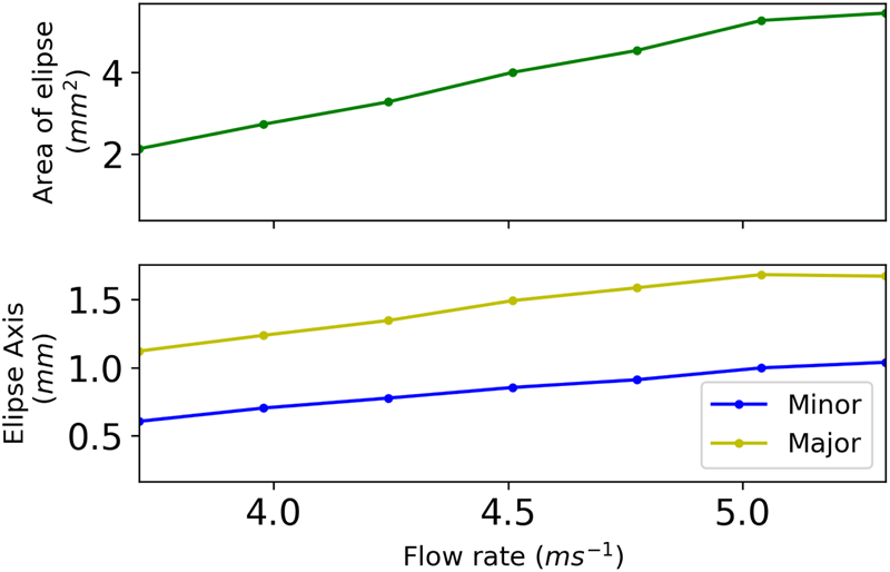
The stable regime had a characteristic rope of water around the edge of it, which stopped the edge breaking up into droplets (Fig. 3). For some angles creating the film skewed allowed the formation of a stable window, whereas a perpendicular film to the plane of the water stream was unstable. An angle of  $128.0 \pm 0.7^\circ$, which was stable for perpendicular and skewed water films, was chosen and used for the later stages of the work. Once this was found, then the flow rate was important for defining the size of the window, as shown in Figures 3 and 4. A linear relation between flow rate and area was found.
Size of the water window with a flow rate from the pump set from 6000 to 11,500  ${\rm \mu } {\rm l/min}$; a linear relation between window size and flow rate was found over the range of exit velocities investigated.
Measurements of surface thickness
The thickness of the pure water film through 100  ${\rm \mu }$m nozzles was measured using the reflection of a white light emitting diode. The light that is reflected of the back surface ( $R_1$) interferes with the light reflected off the front surface ( $R_0$). The refractive index of air is $n_{{\rm air}} = 1.0$ and of water $n_{{\rm water}} = 1.33$.
 $$R = \left\vert {n_1 - n_2\over n_1 + n_2}\right\vert ^2.$$
The reflections calculated from Eq. (1) show the beam reflected from the front surface is  $2\percnt$ of the total incoming beam and from the back surface is $1.97\percnt$. So the value of $R_0 = 2\percnt$ and $R_1 = 1.93\percnt$. Since most of the light is contained in the first transmission, $T_1$, successive reflections can be ignored. The film has AR properties if the reflection $R_0$ destructively interferes with $R_1$. The reflected light is measured with a spectrometer, and the thin film has the properties of an etalon, as the two surfaces of the film are neither fully reflective or transmissive. The spectrum of the light is modified, and the peaks are separated in frequency space by the free spectral range:
 $$\nu_{{\rm FSR}} = {c \over 2 d n}$$
c the speed of light, n is the refractive index, and d is the path through the water, which then relates to the thickness:
 $$t = d\cos\lpar {\rm \theta}\rpar $$
where θ is the angle of incidence on the water film.
Figure 5 shows that the thickness of the water windows created by the 100  ${\rm \mu }$m capillaries was not flow rate dependent for the range of flow rates examined, 3.5–5.5 m/s1. When the film formed normal to the water jets (in the “z” plane from Fig. 1) its thickness was $2.10 \pm 0.06 \, {\rm \mu } {\rm m}$, and a skewed window ( ${\sim }30^{\circ }$ to normal) had a thickness of $1.6\pm 0.3\, {\rm \mu }{\rm m}$.
The thickness measurement of a stable window, showing that the thickness was constant for the different flow rates. The thickness of the skewed window was found to be  $2.10 \pm 0.06\, {\rm \mu }{\rm m}$ (ignoring anomalous points at 10,000) and the normal window, it was $1.59 \pm 0.32\, {\rm \mu } {\rm m}$. The capillaries were changed between these measurements from 10.46 mm and 10.15 mm long to 10.20 mm and 10.32 mm long, which allowed the formation of a stable perpendicular window.

Stability characterization
The pointing stability of the laser after reflection from the plasma mirror is important. A measurement of how much the pointing was fluctuating was taken and is shown in Figure 6. The stability of the window was different in the two characteristic planes of the film. It was measured at  $1.09\pm 0.06$ mrads around the y-axis as indicated in Figure 1 and $0.088 \pm 0.005$ mrads around the z-axis. The large difference in stability in the two axis comes from the fact an offset of the two jets in “z” plane on the order of microns changes the skew angle of the window around the “y” axis. This means any vibrations in the system will reduce the pointing stability in this axis. For a “y” motion, the collision point would move up or down on each stream, which would have a small change in the angle of incidence. However, this angle is far less sensitive to small changes.
The pointing of the probe laser spot after reflecting off the water window. The stability measurement was created from a video with a exposure time of 1/83 s and tracking the main feature of the reflection. The stability is different in the two directions, the Z had a stability of  $1.09 \pm 0.06$ mrad and the Y : $0.088 \pm 0.005$ mrad.

High intensity reflection measurements
High intensity reflection measurement experiments were carried out under a vacuum using the lambda-cubed ( $\lambda ^{3}$) laser at the Center for Ultrafast Optical Science (CUOS) at the University of Michigan. This laser utilizes chirped pulse amplification and delivers 800-nm wavelength laser pulses containing energies up to 20 mJ with a full-width at half-maximum (FWHM) pulse duration around 43 fs at a repetition rate of 500 Hz. Due to the limit of the optical diagnostic system, we decreased the system repetition rate to 83.3 Hz by using a chopper in the system. A half-wave plate/polarizer combination was mounted between the target and the laser system, giving control of the incident intensity of the laser using the computer-controlled rotation stage.
The schematic setup for generating the water film plasma mirror is shown in Figure 7. The incoming laser beam has a Gaussian beam diameter of 22 mm and was focused by a lens with a focal length of 650 mm, producing a focal spot around 30  ${\rm \mu }$m diameter. The average power of the beam before focus is 3 W at the repetition frequency of 83.3 Hz. Thus, the maximum intensity on the target in this work was ${\sim }5 \times 10^{16}$ W/cm2. The water film was positioned at the focus of the lens. When the intensity was great enough the surface of the film was ionized, generating a plasma mirror which reflected the remainder of the pulse. The reflected light was imaged onto a CCD camera ( $640\times 480$ pixels each $5.6 \times 5.6\, {\rm \mu } {\rm m}$) via a partially reflecting wedge, to decrease the delivered energy, and a lens. The nozzles were mounted on three-axis xyz stages, allowing the position of the water film to be changed as well as the incident angles of the colliding jets. The inner diameter of the capillaries was 100 ${\rm \mu }$m, and the water flow rate was 6.5 ml/min. This corresponds to a flow rate of 6.9 m/s out of each nozzle, so the liquid moves ~80 mm between laser pulses. The chamber was under vacuum for the experiment, to avoid the generation of air plasma or laser filamentation. It should be noted that the vapor pressure of water is 20 Torr at room temperature, but the effect of the vacuum on the water film was uncharacterized for this work.
Schematic of the experimental setup for a water film plasma mirror. The laser pulse is focused using a 650-mm focus length lens into a pure water film from two capillary water nozzles having an inner diameter of 100  ${\rm \mu }$m. The reflection of the laser from the water film is attenuated by a wedge and passes through the lens to be imaged onto the CCD. The water film is controlled by a water pump, and the capillaries are mounted on a x-y-z-rotation stage.

The spectrum of the laser before and after the plasma is shown in Figure 8. It is clear that the center wavelength has a blue shift of 60 nm following the plasma mirror. The FWHM of the laser pulse spectrum increases; however, it is unlikely that this indicates any additional pulse compression. Rather, the presence of blueshifting is likely attributable to ionization of the background water vapor (20 Torr) inside the chamber (Hou et al., Reference Hou, Easter, Mordovanakis, Krushelnick and Nees2008). This may also have reduced the transmitted energy measured in the experiments as the “neutral density” filters used were chosen for their spectral dependence in the range from 750 to 820 nm. The other viable liquid for stable films was ethylene glycol which has a lower vapor pressure. This would reduce the background vapor and therefore the blue shift. However, we did not investigate this to avoid introduction of carbon into the vacuum system.
The spectrum of the laser before and after the plasma. The dotted curve shows the spectrum of the main laser beam, as a reference. The solid curve shows the spectrum after the water film plasma mirror. The FWHM of the spectra becomes wider after plasma mirror and there is also a blueshifting.

To characterize the reflectivity of the water plasma mirror, the laser was operated at either at 83.3 Hz or in single-shot mode. The effective reflectivity of the water film as a function of the intensity is shown in Figure 9. The effective reflectivity is measured by taking the ratio of the integrated signal measured on a CCD camera directly before and after the water film. In Figure 9, each data point represents an average result of 500 images obtained from the CCD camera. With the near-normal Fresnel intensity reflection being 2%, reflected by both surfaces of the water film the total relative reflected power without plasma should to be 4%. For future experiments, the thickness of the film should be matched so its thickness is  ${n \lambda }/{4}$, where n in an odd integer, the film should display AR properties and the reflectivity reduced (Hecht and Street, Reference Hecht and Street2010). At an intensity below $7 \times 10^{14}$ W/cm2, the reflectivity was 4% which matching the expected value. The threshold intensity of $7 \times 10^{14}$ W/cm2 is somewhat higher than the damage threshold measurements of a solid target ( $10^{14}$ W/cm2) (Kautek et al., Reference Kautek, Krüger, Lenzner, Sartania, Spielmann and Krausz1996; Ziener et al., Reference Ziener, Foster, Divall, Hooker, Hutchinson, Langley and Neely2003). Above this threshold, the effective reflectivity rises up to 30% at an intensity of about $5 \times 10^{15}$ W/cm2, similar to the intensity with the laminar flow water film claimed by Panasenko et al. (Reference Panasenko, Shu, Gonsalves, Nakamura, Matlis, Toth and Leemans2010). The measured maximum effective reflectivity is lower than those liquid jet experiments.
Assumed reflectivity of the pure water film using a pulse duration of 43 fs and repetition rate of 83.3 Hz. The intensity was varied by rotating the half-wave plate.

The difference in reflection between a single-shot mode and a high repetition rate was investigated. Figure 10 shows the reflectivity trend with intensity for the two operating regimes. This blue-shift modifies the laser to a spectral region where the CCD detector sensitivity is higher and throughput of the optical filter has increased, which compromises the quantitative nature of the measurement (Figure 8). However, since the general trend is consistent with single-shot operations, with the reflectivity for both cases normalized to its maximum value, we conclude that the water film studied may be suitable for use as a plasma mirror.
Comparison of repetition rate and plasma mirror material with water for single-shot data and 83 Hz results.

Reflected beam profile measurements
The beam profile reflected off the mirror is important. Ideally, a spot would remain a spot after reflection, showing that the mirror does not deform the beam profile. A wavefront sensor, Shack–Hartmann design, measured the amount of distortion. The Shack–Hartmann has an array of small lenses which all focus onto the CCD chip on a camera. If a flat wavefront is imaged, the lenslet array will create an evenly spaced array of spots. However, if the wavefront has distortions, the focus point of each individual lenslet is altered, meaning that the bright spots on the CCD move. By tracking this movement, it is possible to calculate what the wavefront would have been.
The probing HeNe beam was measured to have an area of ≈0.5 mm2. An assumption made for this calculation was that the wavefront shape was not changing with respect to time. We saw from the stability measurements an overall motion but no relative motion. This is a positive sign, as theoretically it will be possible to build an optic to correct for the distortion of the spot, therefore making a larger area of the plasma mirror usable. Optics surface flatness is measured in the number of wavelengths shifts per inch and for a good quality optic is greater that  $\lambda / 4$ per inch. Measuring from the center spot to the edge, we see a flatness of ${\approx }900 \lambda$ per inch. The amount of wavefront distortion is far to large for current adaptive optics, such as deformable mirrors, to correct in one go. However, as this is an important problem to solve, it is not unreasonable to assume that an optic could be built to correct for this.
The reflected beam profile had what looked like a severe coma aberration, which might come from a slight curvature of the films surface. The probe beam was reflected of the film in around the Y-axis, due to the lack of space in the Z plane. Therefore, reflecting in a different axis may improve the beam quality.
Conclusion
This work has made measurements assessing the feasibility of a pure water film created by colliding liquid jets for use as a regenerating plasma mirror for high repetition rate (kHz) systems. The flowing water-based plasma mirror has clear potential benefits, including refreshing the surface automatically and avoiding high-Z plasma debris. The maximum plasma mirror reflectivity was 30% which was less than that achieved by the water film produced by Panasenko et al. (Reference Panasenko, Shu, Gonsalves, Nakamura, Matlis, Toth and Leemans2010), but the flow rate is about two orders of magnitude greater. The flexibility of this water film system is enormous: the pressure of the water pump can be controlled and hence the size of the window; the diameter of the nozzles; the relatively angle of the two nozzles; and the film material can be replaced, ethylene glycol being a key candidate.
Comparisons between the regenerating water film in a single-shot mode and a high repetition rate indicate the compatibility of this optic with high repetition-rate laser systems. The stability and thickness measurements show the current setup is close to the required parameters. In addition to improvements to the reflectivity measurements, further work would be to see if changing the capillary size altered the thickness to produce a film with AR properties to improve the ICR.
Acknowledgments
This material is based upon work supported by the Air Force Office of Scientific Research under award number FA9550-16-1-0121, the NSF under grant number 1535628, the Department of Energy under grant number DE-SC0016804, and by the Engineering and Physical Sciences Research Council [EP/K504178/1].


 Open access

