1.0 INTRODUCTION
Morphing wings have been studied since the earliest days of heavier-than-air aviation, no doubt based on the commonplace observation that all birds continuously change the shapes of their wings during flight. The original Wright Flyer used ‘wing warping’ for roll control – a fundamental form of wing morphing. There are many and varied ways that the wings of an aircraft can be altered in shape: the planform can be altered in size or span or sweep, section shapes can be altered, either to change lift magnitude and distribution or to gain vehicle control in pitch, roll, yaw, etc., wings can be twisted to alter effective angles of attack. Aeroelastic effects can be deliberately used to make geometry changes – so-called aeroelastic tailoring. If allowance is made for the activation and deployment of conventional control surfaces, almost all aircraft lifting surfaces change shape in some way or other. One of the key recent drivers in morphing wing technologies has been the adoption of composite materials such as carbon-fibre-reinforced plastics. These have allowed for considerable tailoring of stiffness properties throughout the geometry of the wings so as to allow close control of the shape changes being achieved. In the wings developed here, a careful matching of fibre and foam structural elements is used to govern the shapes taken up by the wing as it morphs.
A good example of what was first seen as a morphing wing development is that of the Grumman F-14 Tomcat built in the 1970s, which was designed to be both an air superiority fighter and a long-range naval interceptor. The first model of this aircraft, the F-14A was built with two different geometry changing mechanisms: a mechanism to change the wing's sweep angle and retractable glove vanes to compensate for adverse pitching moments at high speeds. On the fourth version of the F-14, the F-14D built in 1991, the glove vanes were removed due to their weight and complexity(Reference Baugher1). Since that time many more sophisticated in-flight geometry manipulation systems have been tried and the whole field of ‘morphing aircraft’ has grown enormously, see for example, Refs Reference Maclean, Carpenter, Draper and Misra2-Reference Molinari, Quack, Arrieta, Morari and Ermanni9. Clearly, morphing geometry must not only improve the aerodynamic capabilities of an aircraft, but also cannot have too severe an impact on cost, weight or energy consumption.
Barbarino et al(Reference Barbarino, Bilgen, Ajaj, Friswell and Inman10) provide a comprehensive review of morphing aircraft technology, citing over 300 papers discussing the topic. Vasista et al(Reference Vasista, Tong and Wong11) state that “a morphing wing is a smart, adaptive, active, and reconfigurable wing”. In this article, focus is placed on the deliberate exploitation of the elastic properties of a main wing that is actively deflected between different configurations to provide roll control authority. This concept has been previously studied by Bolinches et al(Reference Bolinches, Keane, Forrester, Scanlan and Takeda12) and can be classified using the scheme of Vasista et al(Reference Vasista, Tong and Wong11) as an out-of-plane morphing wing which uses a change of camber and a compliant mechanism. Bolinches et al manufactured and tested a wing for a 15-kg maximum take-off weight (MTOW) UAV based on finite element analysis and CFD directly controlled by optimisation routines. The wing was designed for the cruise configuration and permitted improvement in drag compared to a conventional wing with active ailerons. Following this, they conducted a study on a wing which included the use of buckled regions to decrease the energy needed for the actuators(Reference Bolinches, Keane and Forrester13). The wing described here has been designed to be mounted on the same 15-kg MTOW Decode Mark IV UAV used in these previous articles(14). Its main characteristics are summarised in Table 1.
DECODE Mark IV UAV characteristics

a Note that the lift/drag ratios are here dominated by parasitic drag elements stemming from undercarriage elements, engine, aerials, etc., which mean that these are worse during cruise than at landing or take-off – essentially the total drag reduction gained by reducing control surface deflection and angle-of-attack after take-off is rather small in such aircraft; the L/D ratios for the wings along, of course, improve during cruise.
2.0 MORPHING WING DESIGN
The wings considered here have been built out of glass-fibre-clad polystyrene foamFootnote † with SLS-nylon 3D-printed inserts acting as ribs, all supported on carbon-fibre spars. In this approach, only the main spar contributes significantly to the overall stiffness of the wing – while this appears at first sight to be structurally inefficient, it has the great benefit of simplicity and allows very low-cost designs to be rapidly designed and built. This significantly speeds up the development cycle for new ideas – no doubt for a production design further effort would be expended on a more sophisticated structural approach, see, for example, Ref. Reference Keane, Sobester and Scanlan15.
The actuator mechanisms used to control the wing shape were also made from SLS nylon. The wing structure has an open slot at the trailing edge to allow the upper and lower trailing-edge surfaces to slide over each other while the sections distort in shape, changing their camber. This shape change is controlled by a series of slotted mechanisms in the trailing edge, one of which is linked to a servo driven actuator mechanism. This system provides overall wing warping much like that achieved in the Wright Flyer via control wires. The wing section shape change is illustrated in Fig. 1. This system develops enough lift variation to control the roll of the aircraft and, crucially, develops less drag than the ailerons of conventional wings.
Superimposed profiles of the morphing wing during movement.
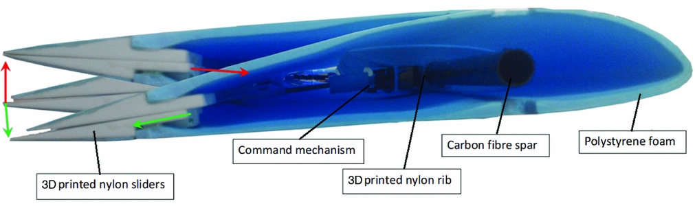
Figure 2 shows the overall layout of the wing – note that the ribs attached to the spar do not join directly to the trailing-edge control slots – this allows the inherent flexibility of the glass-fibre-covered foam wing skins to be exploited as a morphing surface. The wing-tip fence at the outboard end acts to close the trailing-edge slot aerodynamically as well as helping control the tip vortex. The innermost trailing-edge part does not slide but instead provides a slot for a torque reaction peg that is linked to the aircraft fuselage.
CAD model of the morphing wing – Note actuator on fourth rib.
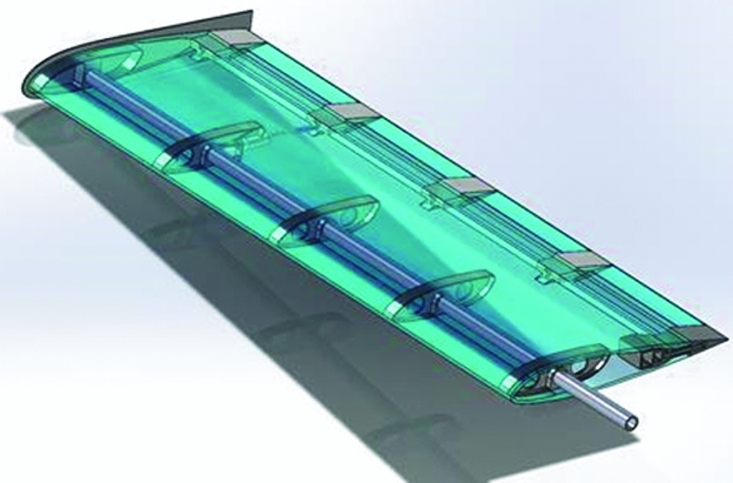
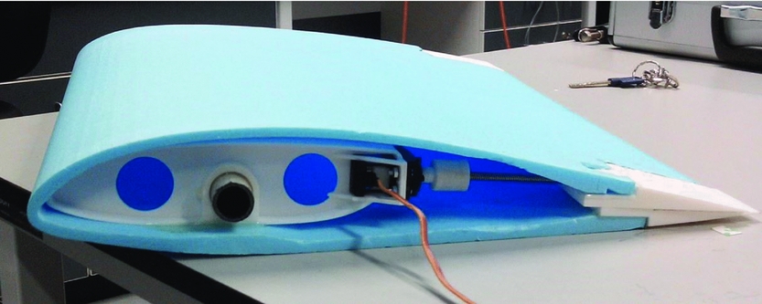
The actuator mechanism consists of a multi-turn servo motor with digital control driving a worm-and-nut system. The worm has a five-way multi-start thread in order to allow a large displacement compared to its diameter and the number of revolutions used. In order to save energy when the servo motor is not activated, the screw is self-locking so it uses no energy at rest, even in deflected positions and when subject to aerodynamic loading – a significant benefit over direct actuating mechanisms such as piezo-electric actuators. The use of selective laser sintering allows the use of a constrained ball socket joint which gives some play to the slider but prevents it from turning along the axis of the screw. The servo motor is mounted on the fourth rib seen in Fig. 2. This position gives the greatest overall wing twist for a given actuator displacement. Figure 3 shows the morphing actuator in situ.
Morphing mechanism in situ in test section.
3.0 OPTIMISATION OF LIFT COEFFICIENT VARIATION
A finite element analysis and CFD based optimisation design search has been carried out to gain the greatest roll control. The goal function used by the optimisation algorithm was the overall lift coefficient of the deformed shape achieved by modifying the thickness of the foam at two positions on the interior of the default wing-section profile. To achieve this MATLAB, Abaqus and the Full potential CFD code, FP were used to construct a response surface surrogate model of the effect of geometry changes on lift. The use of surrogates allows design optimisation studies using expensive analysis codes such as Abaqus to be accelerated towards convergence, see for example, Ref. Reference Forrester, Sobester and Keane16.
3.1 Finite element mechanical analysis model
The mechanical aspects of the design were analysed with the Abaqus FEA 3D code. A plate element approach was not considered here because of the fact that the actuators efforts are parallel to the main fibre of the skin. The principal hypothesis is that the wing skin acts as a linear elastic material within its elastic range. This is important because control action deformations must not permanently deform or break the fibre clad foam skin. Furthermore, the very thin glass fibre cladding is not considered in the modelling, as it is used only to protect the polystyrene foam from fuel damage and minor exterior impacts, and not to change its rigidity.
The wing is made of polystyrene foam for the body of the skin, SLS nylon for the printed parts, and carbon-epoxy for the spar. All these materials are assumed to be homogeneous and isotropic – for the carbon epoxy spar, this is a strong hypothesis, nonetheless the worst yield point and Young's modulus are considered here resulting in an over dimensioning which may be improved in due course. The characteristics assumed for these materials are given in Table 2.
Material properties

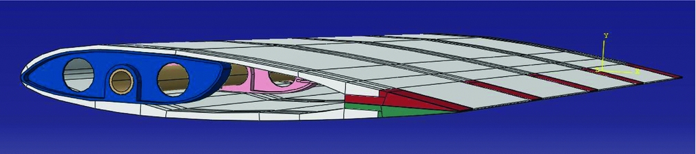
The FEA model is composed of multiple parts, see Fig. 4:
-
1. The foam skin (white);
-
2. The five SLS nylon male sliders (red);
-
3. The five SLS nylon female sliders (green);
-
4. The four SLS nylon normal ribs (blue);
-
5. The SLS nylon rib for the servo (light pink);
-
6. The carbon fibre reinforced epoxy spar (beige).
3D Abaqus model.
The interaction between the different parts – mainly the sliders – is a general self-contact with a friction coefficient of 0.1, added in the first Abaqus analysis step. The sliders are in contact pair-wise and the skin is in contact with the ribs. The normal behaviour is modelled with the default constraint enforcement method. In addition to this contact model, all the different parts are tied together on the surfaces where they will be ultimately be glued during assembly. The only boundary conditions applied are that the extremities of the spar, the first slider edge and the skin which will be in contact with the fuselage are considered fixed (encastre), see, for example, Refs Reference Sellitto, Borrelli, Caputo, Riccio and Scaramuzzino17 and Reference Borrelli, Riccio, Sellitto, Caputo and Ludwig18.
For the purposes of initial testing the actuator mechanism was modelled as a pressure equivalent to a force of 30N on the two parts where the mechanism is fixed (the rib and the upper slider). Subsequently external loads were taken from an aerodynamics analysis calculated using a full potential CFD code.
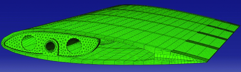
All the different parts were meshed separately (Fig. 5). The foam is the most important part of the model as it generates the aerodynamic characteristics of the wing. It has been meshed with brick elements using at least four elements in the thickness to ensure reasonable accuracy. The other critical parts are the sliders where contact takes place and where the pivot and rail of the sliders must be finely meshed. The remaining parts were meshed with tetrahedral elements due to their geometric complexity.
3D Abaqus mesh.
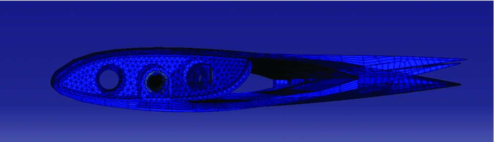
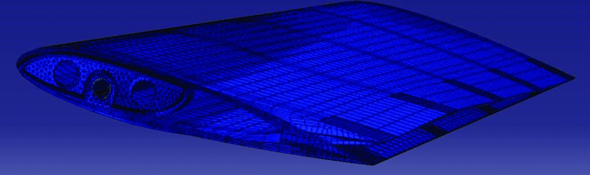
As there were many surfaces in complex contact the resulting model was analysed using the Abaqus explicit method which helps ensure convergence. The results from this analysis, which took nearly 24 hours to converge on a desktop PC, are shown in Figs 6 and 7.
3D deformed and un-deformed wing sections.
3D deformed and un-deformed wing superimposed.
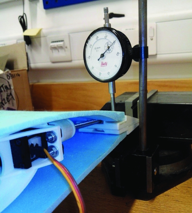
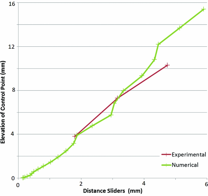
Preliminary comparisons of the computed results with a small test part of only two ribs showed good agreement with the analysis in use (Figs 8 and 9). The numerical results show a non-linearity which may be due to the fact that the complex ribs attachment is not always in contact during the deformation.
Experimental measurement of part deflection on short test section.
Comparison of computational and experimental deflections.
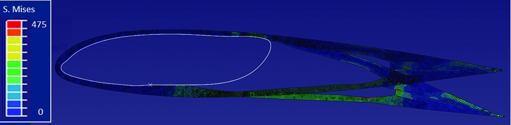
In order to allow a calculation that runs at more reasonable cost, the wing was next considered to have a linearly varying twist deformation along the spar. This allows a two-dimensional approach to be taken during structural analysis. This approximation gives results not too far from the full 3D model, but at a fraction of the computational cost. The geometry definition, meshing and analysis steps for this analysis were coded in Python so as to calculate the deflected shape of the section for a given pressure loading in an automated fashion suitable for use with an optimisation algorithm. The resulting 2D Abaqus model and typical deflected shape are illustrated in Fig. 10.
3D deformed and un-deformed mesh of the Abaqus finite element analysis model.
3.2 Aerodynamic model
Since the morphing wing design considered here fundamentally relies on the elastic flexibility of the structure, it is important to include both actuator and aerodynamic loads when assessing designs. Here, aerodynamic pressure loads are computed using a full potential Computational Fluid Dynamics (CFD) code based on the work of the Engineering Science Data Unit(19). FP is coded in Fortran for calculating the flow field and aerodynamic forces of an isolated wing or a wing-body combination in a subsonic free-stream, including the effect of (weak) shock waves. It uses a relaxation process to solve finite-difference forms of the full nonlinear velocity-potential equation for the inviscid flow around the three-dimensional geometry, optionally followed by empirical viscous boundary-layer corrections. This method has been implemented in MATLAB by Toal (see Appendix E of Ref. Reference Toal20).
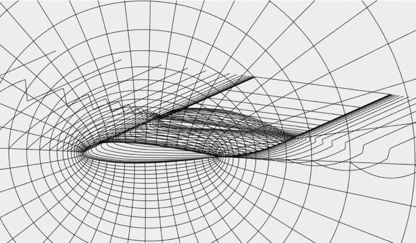
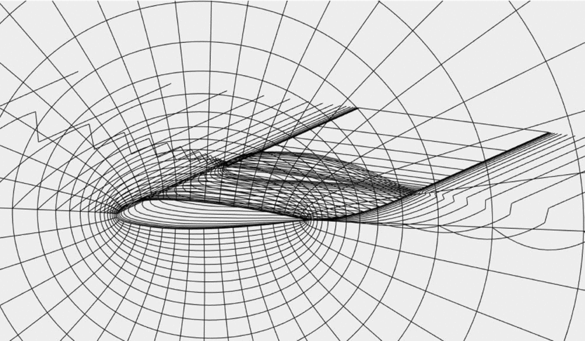
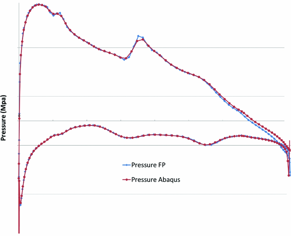
To generate the deformed shape for aerodynamic analysis, the 2D section analysed with Abaqus is assumed to be the part of the wing where the actuator is placed. The area of the wing between the fuselage, where the profile cannot morph, and the section moved by the servo is taken to be a linear interpolation between these two profiles. The servo action is modelled using a linear pressure of 0.2 MPa.mm–1. A kinematic link between the sliders is also added in order to prevent them from disassembling. The rest of the wing is considered to be deformed as per the section with the servo. This deformation distribution is close to that observed on test wings. This allows a more accurate result than just assuming a uniform rate of deformation along the wing. The 3D mesh of the deformed wing used in FP can be seen in Fig. 11. Figure 12 shows a typical pressure plot from an FP solution.
3D mesh of the deformed wing in FP.
Typical pressure plot from FP solution.
3.3 Fluid structure coupling
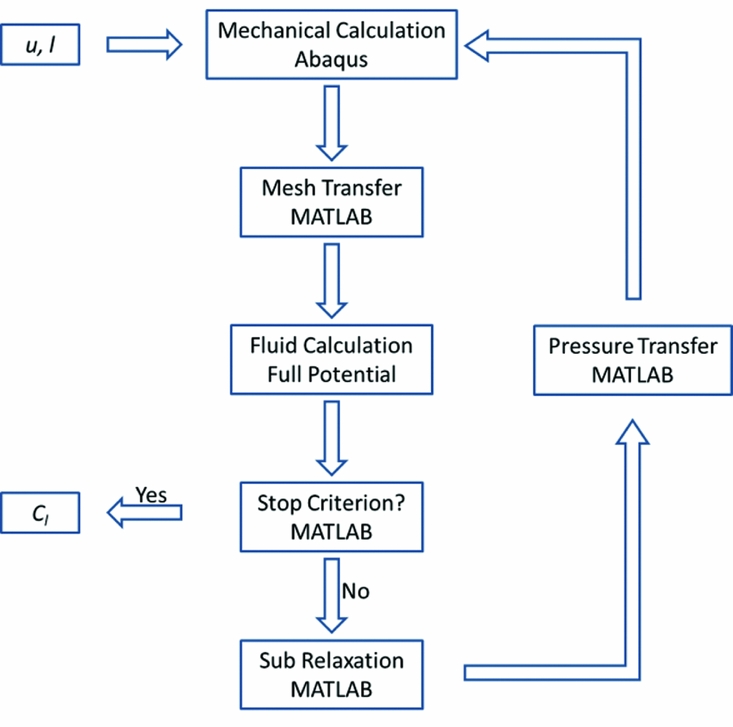
The fluid structure coupling between Abaqus and FP has been implemented in MATLAB and is summarised in Fig. 13. Here u and l are, respectively, the upper and lower thickness variations of the foam skin and Cl is the lift coefficient of the wing. Since changes to the structural model lead to alterations in the loaded shape, which in turn affect the aerodynamic behaviour and consequent pressure loading, a relaxation approach is used when solving for the converged shape to ensure stability. The stopping criterion is that the root mean square of the difference of pressure between Abaqus and FP is below 10–3 MPa.m–1.
Aeroelastic analysis algorithm.
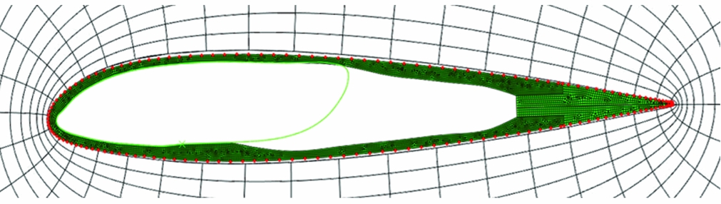
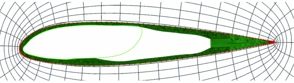
As the structural and aerodynamic meshes differ, a mesh transfer process is used to link the two analysis domains as presented in Fig. 14, where the red spots are the points interpolated from the mechanical mesh to the fluid mesh. Between these points the pressure is linearly interpolated from the fluid mesh to the mechanical mesh.
Abaqus and FP meshes superimposed.
3.4 Optimisation algorithm
The optimisation search has then been carried out using the surrogate-based optimisation toolbox developed in MATLAB by Forrester et al(Reference Forrester, Sobester and Keane16). The initial sampling plan used in surrogate construction was chosen to consist of eleven points placed using the Latin hypercube method. The analysis model described above is then used to evaluate the design at these points. Using these first results, a Kriging model is constructed which is searched for the maximum of the Expected Improvement function with a Genetic Algorithm. A new design is then calculated and added, with this update process being repeated 22 times. The final Kriging model is shown in Fig. 15. A valley of interest clearly appears around a value of lower thickness variation of 0 and of upper thickness variation of 0.4; corresponding to a total lower thickness of 4.4mm and a total upper thickness of 7.5 mm. The resulting Kriging model can be seen in Fig. 15.
Kriging model of the lift coefficient: 3D plot (a) and plan view with sample points (b).

Similar optimisation studies have been carried for a range of angles of attack from 5° to 10° at the desired cruise speed of 24 m/s. The area of best performance appears at the same place in all cases so this design was chosen to build the set of morphing wings for wind-tunnel and flight tests.
4.0 WING CONSTRUCTION AND TESTS
4.1 Wind-tunnel tests
The wing parts were constructed using a hot-wire polystyrene foam cutter and 3D SLS nylon printing machine (Fig. 16). After assembly, they were tested in the R.J. Mitchell wind tunnel at the University of Southampton (Fig. 17). The wind-tunnel dimensions are 3.5 × 2.4 m and the turbulence level is below 0.2% – note the circular plate used to represent the fuselage boundary. No wall corrections were taken into account initially because the surface area ratio of the wing on the test section is lower than 1.5%. The conventional wings, which were designed for the Mark IV UAV and which have a similar area but differing aspect ratio, were also tested in order to directly compare to the results for the morphing wings (see Fig. 17). Both sets of wings were tested for landing, take-off and maximum cruise speed, for different angles of attack from –5° to 10° and for two positions of the roll control mechanism: activated and not. For the conventional wings this corresponds to aileron deflection angles of 15° and for the morphing wings to the maximum deflection calculated using the fluid structure algorithm. This maximum deflection is the one corresponding to a force of 30 N used for the design of the mechanism.
Wing parts under construction: foam parts (a) and SLS nylon parts (b).

Wings in wind tunnel for test: morphing (a) and conventional (b).

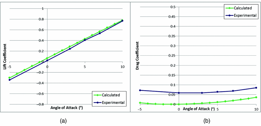
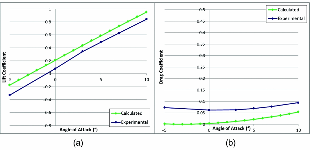
Figure 18 shows a comparison between the experimental and predicted lift (a) and drag (b) coefficients for the morphing wings in the un-activated case, while Fig. 19 is for the case when the morphing is activated. The measured drag is somewhat worse than the prediction due to the fact that in this study the viscous drag option of FP was not used. Further calculations made with the viscous drag option activated for the angle-of-attack of 5° give a drag coefficient of 0.025 which is closer to the experimental result 0.05. The lift, which was the target of the optimisation study, is reasonably well predicted for this first study, particularly in the un-activated case.
Lift (a) and drag (b) coefficient at 24 m/s; no morphing.
Lift (a) and drag (b) coefficient at 24 m/s; morphing activated.
The second set of results compares the morphing and conventional wings. The experimental lift-to-drag coefficient curves of both wings have been plotted for different air speeds and angles of attack, in both un-activated (a) and activated states (b) (see Fig. 20). As the wings do not have the exact same shape, the curves are not directly comparable but some conclusions can already be drawn.
Experimental lift/drag coefficient comparison, un-activated (a), activated (b).
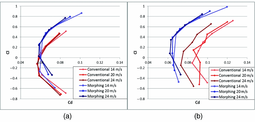
What is most noticeable about these graphs is that the morphing wings give better results than the conventional ones. The activation of the mechanism of course increases the lift of both wings, and it also creates a variation of drag. However, the additional drag created by the morphing wings is much smaller than for the conventional wings, this being the whole aim for adopting this form of control. Clearly, the absence of hinge gaps diminishes turbulence and separation, and so lessens drag. The lift variation could no doubt be improved further with additional servos but is already sufficient for flight tests. This comparison underlines that comparable flying properties can be obtained with the morphing wing design and besides, what is more important, that the relative lift-to-drag variation due to activation is better for the morphing wings than for the conventional ones.
4.2 Flight tests
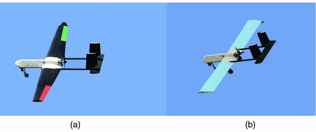
After the wind-tunnel tests, the two sets of wings were tested in flight conditions. The tests consist of measurements of bank angle variation while trying to make the UAV move from maximum to minimum bank angle as rapidly as possible. The data were captured at a frequency of 50 Hz. The UAV was also flown over all its normal flight configurations to ensure it retained full capabilities with the morphing wings. Both wings sets can be seen in flight in Fig. 21 (conventional (a) and morphing (b)).
UAV Mark IV flying with conventional wings (a) and morphing wings (b).
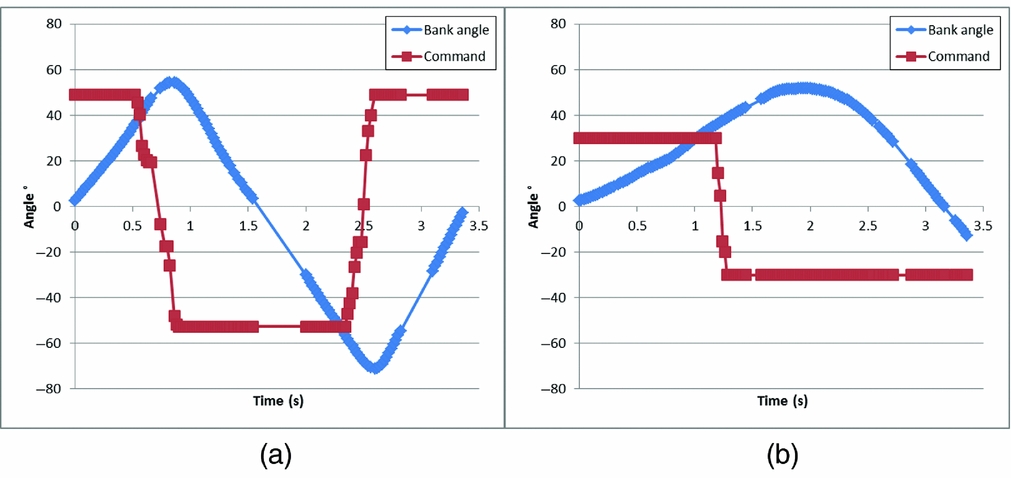
The movements of the morphing UAV were smooth, and as predicted, the morphing-wing variant was slower to respond because of the slower activation speed of the multi-turn servo used to drive the worm gear. However, this did not prevent it from flying in a perfectly acceptable and controllable fashion. Some samples of the data measured during the flight for the conventional wings (a) and for the morphing wings (b) can be seen in Fig. 22. The bank angle of the UAV and the command sent by the pilot to the servo controlling the ailerons or warping the wing are shown. The mean roll rate has been calculated on a period of 0.2 second, leading to the roll rate performance figures detailed in Table 3.
Typical bank and command angle for conventional (a) and morphing wings (b).
Comparison of the extrema roll rates for conventional and morphing wings

Note also that the morphing wings showed a noticeable asymmetry which no doubt arose from the greater complexities experienced in construction and assembly. In future developments, additional care in manufacture should significantly reduce this. To place these roll rates into perspective, note that it only takes 1.5 seconds for the morphing UAV to go from the neutral position to the maximum bank angle tested of 50° for the speed considered, which is quite acceptable for this kind of aircraft. At the same time, the aerodynamic drag of the wings has been significantly reduced during control operation.
5.0 CONCLUSIONS
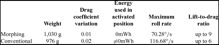
A set of twist morphing wings which use a change of camber and compliant wing covers has been designed for a small 15-kg UAV. These wings provide a smooth and energy-efficient way of providing roll control with a significantly improved lift-to-drag ratio compared to standard wings fitted with conventional ailerons. The morphing wings weigh only 54 g each more than the conventional wings. By using a self-locking drive thread, these wings also allow useful energy saving during flight which can be a non-negligible advantage for long flights.
A numerical optimisation process has been developed and implemented in MATLAB, Abaqus and a Full Potential CFD code to design the shape of wing structure used. This algorithm has been adopted to get the best lift variation possible during activation of the morphing mechanism.
Following design optimisation, a set of morphing wings was built and tested in a wind tunnel and in flight. They provide a slower but sufficient roll control for the operational requirements of the UAV under consideration. An overall comparison between the conventional and morphing wing considered here is summarised in Table 4.
Final comparison between conventional and morphing wings designed to the same load factor of 5 g