


Impact Statement
The high-shear atomizer/gas turbine swirl cup finds application in gas turbine engines such as CFM-56, TALON-X combustors. The fuel delivery nozzles employed are mostly of the simplex-pressure and duplex pressure type (see supplementary figure S1 available at https://doi.org/10.1017/flo.2022.25) to inject the fuel in the form of a hollow cone uniform sheet. These fuel nozzles are highly prone to clogging of orifices and collapse of the hollow cone sheet at high pressure and flow rate. Further, it requires large differential injection pressure, thus work is limited to a narrow air-fuel ratio. These constraints can be avoided with a discrete radial-jet fuel nozzle housed in the present configuration of a high-shear atomizer. The compact recirculation zone and excellent atomization capability achieved in the current atomizer configuration would help in shortening the combustor length, and consequently the weight and cost. The sector-flux distribution of spray in the azimuthal plane shows that the discrete nature of the fuel nozzle can be mitigated, and a uniform distribution of the fuel mixture can be achieved with a discrete radial-jet fuel nozzle, an important parameter to reduce NOx in the rich-quench-lean concept. Overall, the study shows the potential to replace the simplex-pressure-swirl, duplex-fuel nozzle with a discrete radial-jet fuel nozzle with proper atomizer design in the gas turbine industry.
1. Introduction
Liquid fuel is a major power source for most power generating units such as land-based and air-based gas turbine combustors, rocket engines, industrial burners etc. The high energy density per unit volume for liquid fuel makes it a better candidate than gaseous fuel for an air-breathing engine/combustor.
The fuel injection process significantly impacts the proper working of gas turbine engines. The fuel injection technique, its effective atomization, uniform spatial distribution of fuel in the reacting primary zone of the combustor dome control the ignition, exit temperature pattern, liner hot spot region, blow out, NOx, soot and the formation of other pollutants (Reference McVey, Russell and KennedyMcVey, Russell, & Kennedy, 1986). These factors make the fuel injection process a crucial event to achieve good performance of a gas turbine combustor. An airblast atomizer is employed to achieve superior fuel atomization and mixing. The most accepted airblast atomizer is a combination of air swirlers and a fuel injection nozzle in most modern gas turbine engines. This combined pair is well known as a high-shear injector/atomizer.
A fuel atomizer should be capable of generating the desired atomization quality over a wide operating range of an engine with a minimum requirement of fuel injection pressure. The fuel nozzle plays a key role in dictating the resulting atomization quality at the exit of a high-shear injector/atomizer. Reference Cohen and RosfjordtCohen & Rosfjordt (1993) reported that the resultant spray distribution at the high-shear injector's exit largely depends on the fuel nozzle type rather than swirler type. A fuel atomizer using the simplex-pressure-swirl nozzle has limitations. The hollow-cone spray sheet generated by a simplex-pressure-swirl nozzle usually collapses, leading to poor atomization and fuel distribution beyond its rated working pressure and fuel discharge rate. This limitation is overcome by a duplex-fuel (dual-orifice) nozzle, which can work effectively over a wide range of power demands in a gas turbine engine. At low power demand, the primary fuel circuit operates and at higher power load, the secondary fuel line delivers a higher fuel flow rate. Thus, the duplex-fuel nozzle requires a higher differential pressure to deliver the fuel at a high load, since the fuel flow rate is proportional to the square root of the pressure difference. The high-pressure requirement of the fuel nozzle makes the system bulky and costly. The main drawback of a duplex nozzle is the potential plugging of small orifices and passages by containments present in the fuel (Reference LefebvreLefebvre, 1995). The duplex nozzle also has an operating limit since the hollow-cone sheet collapses at high operating pressures of the combustor.
The discrete radial-jet fuel nozzle shows the potential to overcome these limitations. However, some challenges are associated with this kind of fuel nozzle. One of the major challenges is to achieve a uniform azimuthal distribution of the spray. These milestones could be accomplished by using a discrete radial-jet fuel nozzle in combination with the proper design of a high-shear atomizer. All the existing literature shows that most of the experiments concerning high-shear atomizers have been carried out with a simplex-pressure-swirl nozzle i.e. fuel was injected in the form of a hollow sheet over the prefilmer. Hence, it becomes necessary to evaluate the performance of a high-shear atomizer/injector with such a fuel nozzle.
The flow aerodynamics of multiple radial/axial swirlers in a high-shear atomizer dictates the spray characteristics such as the drop size and patternation (Reference Wang, McDonell and SamuelsenWang, McDonell, & Samuelsen, 1993). The strong swirling flow creates a negative pressure gradient at the centre of the rotational axis of flow, which leads to the reversal of a part of the airflow leading to the formation of a central toroidal recirculation zone (CTRZ) (Reference SarpkayaSarpkaya, 1971). A non-dimensional parameter, the swirl number (SN), was introduced to characterize the swirl flow, which is the ratio of the axial flux of azimuthal momentum and the axial flux of axial momentum (Reference Beer and ChighierBeer & Chighier, 1972; Reference Syred and BeérSyred & Beér, 1974). The CRTZ reduces the flame length and stabilizes the flame by recirculating the hot flow against the high-speed incoming air stream (Reference Gupta, Lilley and SyredGupta, Lilley, & Syred, 1984). The CTRZ is believed to be a major player that influences the flow topology of the spray and the associated dynamics of the flow field (Reference Kumar, Malavalli, Chaudhuri and BasuKumar, Malavalli, Chaudhuri, & Basu, 2020; Reference Rajamanickam, Potnis, Kumar and BasuRajamanickam, Potnis, Kumar, & Basu, 2020).
Several experimental studies have been conducted to characterize the high-shear atomizer; most of them were either carried out with only air or with spray using a fuel nozzle that produces a hollow-cone liquid sheet. Now, as mentioned earlier, the discrete radial-jet fuel nozzle can deliver the fuel properly at both the low and high end of the power demand. Hence, evaluating the performance of a high-shear atomizer/injector with a radial-jet fuel nozzle becomes significant. Reference Cohen and RosfjordtCohen & Rosfjordt (1993) examined several configurations of high-shear atomizers with a radial-jet fuel nozzle. However, only spray patternation had been selected as a benchmark to evaluate the performance. Nevertheless, several authors (Reference Mongia, Al-Roub, Danis, Elliott-Lewis, Jeng, Johnson and ViseMongia et al., 2001; Reference Wang, McDonell, Sowa and SamuelsenWang et al., 1992, Reference Wang, McDonell, Sowa and Samuelsen1994) have considered droplet sizing also as one of the major parameters with which to characterize the performance of atomizers. The flow structure generated by swirlers strongly influences the spray characteristics. Hence, information about the spray flow field (such as flow topology, droplet sizes and droplet dispersion) becomes crucial to characterize the performance of the high-shear atomizer housed with discrete jet fuel nozzles.
Strong swirling flows are usually associated with large-scale instabilities such as a precessing vortex core (PVC) and convective vortex shedding, to name a few. The intensity of these instabilities is believed to scale with the size of the CTRZ, swirl strength, mode of fuel entry and burner geometry (Reference SyredSyred, 2006). Further, the size of the CTRZ is influenced by the geometrical parameters of the swirler. From these perspectives, several researchers have extensively attempted to characterize the high-shear injector and subsequently have tried to understand the governing mechanism of the flow thus generated. (Reference Hadef and LenzeHadef & Lenze, 2008; Reference KilikKilik, 1985; Reference Lin, Wang, Estefanos, Tambe and JengLin et al., 2017; Reference Merkle, Haessler, Büchner and ZarzalisMerkle et al., 2003). Recent studies by Reference Shanmugadas, Chakravarthy, Chiranthan, Sekar and KrishnaswamiShanmugadas et al. (2018 on a gas turbine swirl injector equipped with a simplex fuel nozzle report that droplet size and the atomization process are strong functions of the film formation on a venturi/prefilmer wall, crater size formation and rim thickness at the venturi lips. Further, the fuel nozzle type, manufacturing defect and misalignment have more impact on the spray distribution than swirler design parameters (Reference Cohen and RosfjordtCohen & Rosfjordt, 1993). The research also studied the effect of the flare divergence angle on the flow field generated by a high-shear atomizer (Reference Kumar, Chaudhuri and BasuKumar et al., 2019).
The present study continues our previous work (Reference Kumar, Malavalli, Chaudhuri and BasuKumar et al., 2020), where a simplex-pressure-swirl fuel nozzle (see figure 1a) was used to inject liquid inside an atomizer. The current study aims to evaluate the performance of the present atomizer configuration over a wide range of air–liquid mass ratios (ALRs) values of 4–14. We have discussed the flow field, droplet size and spray patternation at ALRs, which can be achieved using a discrete radial-jet fuel nozzle with a high-shear atomizer. Further, we have linked the occurrence of the most dominant spatial eigenmode with the characteristic length scale (W/Df; W, radial width of CTRZ (in mm) and Df, exit diameter of flare (mm)) of the CTRZ.
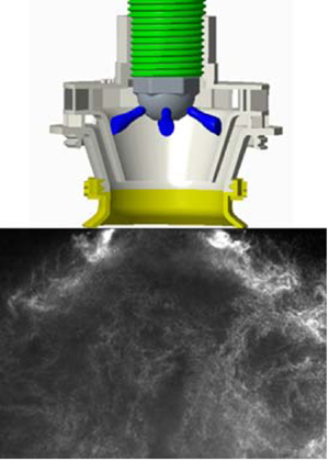
Illustration of fuel injection process in two different fuel nozzles; (a) hollow-cone liquid sheet from simplex-pressure-swirl fuel nozzle, (b) discrete liquid jets from radial-jet fuel nozzle, (c) filming characteristics inside venturi for hollow-cone liquid sheet and (d) filming characteristics inside venturi for discrete liquid jets, ALR ~ 0, (e) high-shear atomizer.
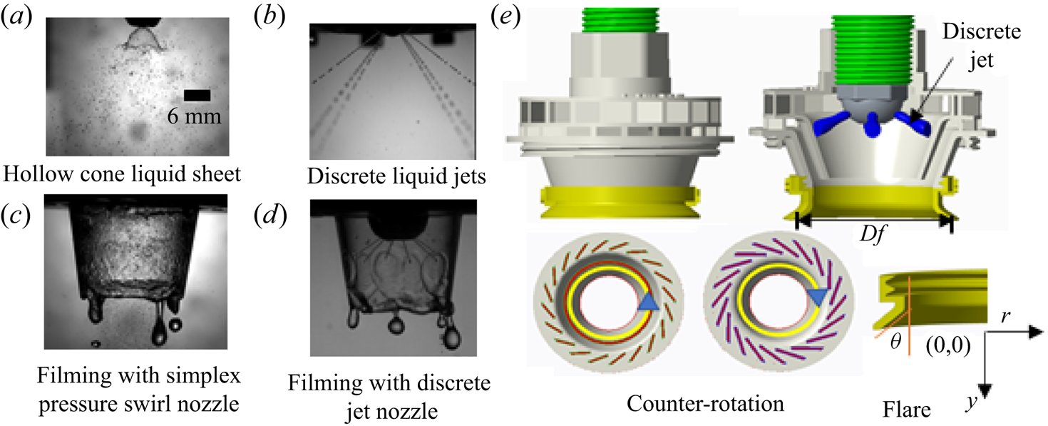
In addition to the potential advantages of the discrete fuel nozzle over the limitation of the simplex-pressure and dual-orifice fuel nozzle, the necessity of the present study lies in the disparity of the film formation and atomization mechanism of high-shear atomizers equipped with discrete jets and a simplex-pressure-swirl fuel nozzle. A pressure-swirl fuel nozzle injects a rotating uniform thin hollow-cone liquid sheet whereas a discrete jet fuel nozzle injects fuel jets, without angular motion with inherent discreteness (see figure 1a,b). The rotation of the liquid sheet provides an additional shearing action to the film and assists in the atomization process in a pressure-swirl fuel nozzle, unlike discrete jets. Discrete radial-jet fuel nozzles inherit non-uniformity in film thickness, whereas the pressure-swirl fuel nozzles offer relatively consistent uniform film over the prefilming surface (see figure 1c,d). Further, the interaction of the airflow and liquid jets resembles jets in cross-flow problems. The liquid jet undergoes different breakup modes based on the co-flow jets’ momentum flux ratio (MR). Below a certain MR, the jet impacts the prefilming surface as a liquid sheet. However, above a critical MR, the jets disintegrate into droplets which subsequently impact over the surface leading to the formation of a film.
2. Experimental methodology
2.1 High-shear atomizer design and description
The high-shear atomizer employed in the present study combines a discrete radial-jet fuel nozzle and a swirl cup (see figure 1e). Detailed descriptions are given in the supplementary material § S2. The design parameters of the swirl cup considered in the present study are listed below, and each term is explained in the supplementary material § 2.
(i) Split ratio (γ).
(ii) Mixing length (η).
(iii) Flare exit angle (θ).
(iv) Swirler configuration: co-rotation (COR) and counter-rotation (CR).
It should be noted here that the fuel nozzle is kept unchanged across the test cases. The swirl cup of the atomizer employed in the present study is a common form that finds application in gas turbine combustion engines (Reference Wang, Hsieh and YangWang et al., 2005; Reference Xiao and HuangXiao & Huang, 2016). The geometric details of the swirl cup are given in table S1 in the supplementary material.
Eight configurations of the swirl cup are developed (see table S2 in the supplementary material) by varying relevant dimensions of the swirlers such as the blade height, flare angle, flare length etc. Case C1 is considered as a reference case and is called the base configuration. The detailed design procedure has been discussed in our previous publication (Reference Kumar, Malavalli, Chaudhuri and BasuKumar et al., 2020).
2.2 Experimental set-up and test conditions
The experiments have been conducted in an open chamber at ambient temperature and pressure conditions. The experimental set-up utilized to conduct the experiments is shown in figure S2 of the supplementary material. The relative position of the fuel nozzle with respect to the venturi exit was kept unchanged. The fuel nozzle had six holes (diameter 0.5 mm) at a certain angle to the nozzle axis. The flow rates of air and water were 3000 slpm and 250 mlpm, respectively, for all cases. In the present experiment, while doing spray particle image velocimetry (PIV), droplets generated in the spray were used as a scattering medium in a longitudinal plane and no seeding particles were introduced into the air. Most droplet (80 %) sizes were less than 13 μm. Consequently, the calculated global stokes number is found to be within 0.8 for the major population of the spray.
Diagnostic techniques such as high-speed PIV, phase doppler interferometry (PDI) and a mechanical patternator were employed to capture the relevant information. The detailed information on the experimental set-up, various diagnostics and related uncertainty are given in supplementary material § S2. The non-dimensional numbers such as SN 5 (swirl number calculated at 5 mm from the exit), the Reynolds numbers of primary (Re)p and secondary swirlers (Re)s, the non-dimensional width and length of the recirculation zone are given in table 1. Further, another parameter representing the interaction of two coaxial jet flows, namely MR, is calculated and is much greater than 1, which shows a strong interaction between the fuel jet and air. A detailed description of the calculation and methodology is given in the supplementary material.
Experimental test cases.

3. Result and discussion
3.1 Global flow field of spray
Flame stabilization is one of the essential parameters that is needed in a gas turbine engine to light up the upcoming fresh reactant mixture over its operating range. Flame holding is achieved through the CTRZ that reverses a fraction of the net flow aerodynamically. As mentioned earlier, swirl flows inherit instabilities such as the PVC whose intensities scale with the size of the CTRZ. Further, it affects the flame stability, combustor length, NOx production etc. Hence, the atomizer must be capable of creating a CTRZ over a range of operating conditions. In this section, the atomizer performance is examined by changing the design parameters while keeping the flow variable (ALR) fixed. Subsequently, we alter the ALR freezing the design parameter as discussed in the following sub-sections.
3.1.1 Flow topologies of spray pertaining to design changes of the atomizer
In this sub-section, we discuss the global flow field of the spray with variations in the design parameters. To characterize the flow topology, the non-dimensional numbers W/Df and L/Df represent the mean width and mean length of the CTRZ. Here, Df (Rf) is the flare exit diameter (radius). We have used the momentum-based swirl number (using (1) in the supplementary material) calculated by using velocity components of the flow field measured from the phase doppler particle analyzer experiment. The momentum-based swirl number will represent the true characteristics of swirling flow, provided the velocity components are measured in the same time domain over a plane in such a complex atomizer. In this study, the swirl number (SN 5) is calculated by using the axial and tangential velocity components acquired simultaneously using three-dimensions PDI measurements at 5 mm from the exit plane.
The streamline contour shown in figure 2 represents the time-averaged flow structure of the CTRZ across all cases. It is noticed in figure 2 that, with a decrease in the flow Reynolds number from the primary swirler, the CTRZ grows spatially. In other words, there is a radial (W/Df) and axial (L/Df) expansion of the CTRZ with a decrease in flow rate through the primary swirler. From the axial velocity contours and profile in figure 3, we notice that a decrease in the air flow rate through the primary swirler results in a drop of the axial velocity of the resultant flow field at the exit. This reduction in axial velocity is more pronounced inside the CTRZ. From the swirl number definition, a decrease in the axial flux of axial momentum will increase the swirl number, as observed in table 1, manifesting as a bigger CTRZ. Comparing cases C1 and C5 (which represents the effect of mixing length), shows that an increase in the mixing length causes shrinkage of the CTRZ in both the radial and axial directions. Further, cases C4 and C5 show that a decrease in flare angle results in the growth of the CTRZ. This elucidates that the size of the CTRZ can be altered through the mixing length or flare angle variation, keeping the internal design of the high-shear atomizer unchanged. It should be noted here that flare is an interchangeable external part of the high-shear atomizer. Thus, flare provides us with more degrees of freedom or feasibility to tune the size of the CTRZ without any modifications to the geometry or design of the atomizer.
Streamline contour of time-averaged velocity over longitudinal plane representing the CTRZ and flow topology; (a) base case, γ = 60 : 40; (b) C2, γ = 50 : 50; (c) C3, γ = 40 : 60; (d) C4, CR  $\varTheta$ = 45°, η = 5; (e) C5, CR $\varTheta$ = 50°, η = 5; ( f) C6, COR $\varTheta$ = 50°, η = 0; (g) C7, COR $\varTheta$ = 45°, η = 5; and (h) C8, COR $\varTheta$ = 50°, η = 5.

Time-averaged axial velocity contours (top row) and profile (bottom row, at y/Rf = 0.75) for base case, C1, γ = 60 : 40; C2, γ = 50 : 50; C3, γ = 40 : 60. The flow topology and functional relations of the length scales of the CTRZ with SN 5 (see supplementary material § 3.1) are similar to what has been reported for the same cases in our previous study (Reference Kumar, Malavalli, Chaudhuri and BasuKumar et al., 2020) with a simplex-pressure-swirl fuel nozzle at ALR = 14.1. This implies that the type of fuel nozzle has a negligible impact on the flow topology in the present design of the atomizer.

Finally, we have introduced the change in relative swirl direction between the two airflows passing through the primary and secondary swirlers to see its effect on the flow topology at the exit of the flare. It should be noted that we have kept the swirl direction of the primary swirler unchanged, and the swirl direction of the secondary swirler has been changed. Comparing case C1 and case C6, it is seen in figure 2 that the relative swirl direction significantly influences the flow topology. It is noticed that, while switching from a counter-rotation to co-rotation swirl motion, there is an increase in swirl number (SN 5), see table 1. The increase in swirl number is due to the increased tangential velocity of the resultant flow in the co-rotating atomizer compared with the counter-rotating one. In a counter-rotating atomizer, the opposite sense of the primary and secondary swirl flows means that they oppose each other compared with the co-rotating swirl flow, where both the swirling air flows have the same rotational sense. Further, in the case of C6, the increase of SN 5 has a pronounced effect on the axial length of the CTRZ compared with the radial length. In other words, on switching the relative rotational sense of the airflow from a counter-rotation to co-rotation atomizer, there is negligible change in the radial expansion of the CTRZ and significant change is registered in the axial length with an increase in swirl number. Researchers (Reference Kumar, Malavalli, Chaudhuri and BasuKumar et al., 2020) have reported similar observations in previous experiments. They attributed the CTRZ topology to the function of the local pressure distribution in radial and axial directions.
3.1.2 Flow topologies of spray at different values of ALR for base case C1
In this subsection, we have focused on the response of an atomizer with the variation of ALR. From a gas turbine engine perspective, it becomes crucial for the engine to stabilize the flame across different load conditions. Hence, an atomizer must create a CTRZ at all operating conditions. The authors believe that the ALR values considered in the present study cover the region of interest for the gas turbine community. Flow topology of spray at selected ALR (4.72; 7.08; 9.44, left to right) conditions is shown in figure 4, which shows that the atomizer is capable of creating the reverse flow zone across a wide ALR range. Interestingly, with an increase in ALR, the CRTZ is stretched radially, left to right, W/Df = 0.74; 0.79; 0.86 and contracted axially, L/Df = 1.183; 1.185; 1.60, respectively. The droplets are small enough, resulting in excellent air/fuel mixing within a short distance of the exit. The rich and uniform mixture is the key point to reduce NOx in rich-quench-lean concept-based combustors (Reference McKinney, Sepulveda, Sowa and CheungMcKinney et al., 2007).
Streamline contour of spray flow field for base case C1 across various ALR values; (a) 4.72, (b) 7.08 and (c) 9.44.

3.2 Droplet size distribution
3.2.1 Droplet characteristics pertaining to design changes in the atomizer.
Droplet lifetime and evaporation rate are strong functions of the drop size which influences the low-emission combustion characteristics. Hence, the study of droplet size is as important as flow structure. In this subsection, we will discuss the effect of the geometrical design parameters of the atomizer on the droplet size distribution at fixed ALR = 14.1. The variation in droplet size in the radial direction is recorded for three axial locations at y/Rf = 0.5, y/Rf = 1.5 and y/Rf = 2.5, as shown in figure 5. Smaller droplets are found near the centre (r/Rf = 0) of the spray, while larger size droplets are found near the spray's edge. This happens since bigger droplets experience larger centrifugal forces than smaller droplets in such a turbulent swirl flow. If we notice the variation in droplet size across the cases at a given axial position, there is not much difference between y/Rf = 0.5 and 1.5 within r/Rf = 1.5. Beyond radial position, r/Rf = 1.5, we observed differences for a few cases. At y/Rf = 2.5, a considerable difference is observed in droplet sizes across all of the cases. This large difference in drop size of 9%–27 % is between the cases C5 and C6, and 2%–26 % for cases C1 and C6 from the centre to the edge. The reason for this can be answered from the streamline contours of cases C5 and C6. If we look at y/Rf = 2.5 for case C5 (see figure 2), the flow surrounding the CTRZ gets merged, which may lead to coalescence of droplets, resulting in an increase of droplet size. The effect of co- and counter-swirl (C6 and C1) is also observed in the study. The difference in drop size is relatively small near the exit, y/Rf = 0.5, and can be considered negligible. However, the difference in droplet size is noticeable at y/Rf = 1.5 and 2.5.
Droplet size at ALR ~ 14.1 across all the test cases C1:C8 for axial positions; (a) y/Rf = 0.5, (b) y/Rf = 1.5 and (c) y/Rf = 2.5.

At y/Rf = 1.5 from the exit of flare, the droplet sizes up to r/Rf = 2 are almost similar and beyond this co-rotation atomizer (C6) yields smaller droplet sizes compared with the counter-rotation atomizer (C1). This could result from the coalescence of droplets in the counter-rotation case. The streamline contours, see figure 2(a–f), clearly show that co-rotation (C6) has radially expanding flow which prevents coalescence, whereas the spray gets coalesced in the counter-rotation case. Finally, at y/Rf = 2.5, the droplet size for co-rotation is relatively smaller than for the corresponding counter-rotation atomizers at all radial locations. The difference in droplet size is more pronounced beyond r/Rf = 1.5. This results from the flow topology (see figure 2a–f) of counter- and co-rotation. Beyond y/Rf = 1.5 downwards, the flow (outer shear layer (OSL)) bends inward and goes straight while the ISL gets merged at y/Rf = 2.25, which may lead to the coalescence of droplets at the centre in counter-rotation. Contrarily, co-rotation leads to diverging flow (OSL and inner shear layer (ISL)), which prevents droplet coalescence.
3.2.2 Droplet size distribution at different values of ALR
In this subsection, we present the effect of ALR on the size of the droplet distribution. It should be noticed that the droplet size variation only for case C1; base case, is carried out at various ALR values. The droplet size variation is measured at three locations, namely y/Rf = 1.5, y/Rf = 2.0 and y/Rf = 2.5 downstream of the flare exit.
The droplet size variation at different ALR is shown in figure 6. At low ALR = 4.72, the droplet size is comparably larger than the other two ALR cases. Further, the variation in droplet size is found to be negligible inside the CTRZ, r/Rf = 1; this is because the finer droplet gets trapped inside it. Across shear layers, there is a considerable difference in droplet size with vertical distance from the flare exit. At y/Rf = 1.5, the droplet size is larger than that at y/Rf = 2.5. This suggests that, in downstream locations, secondary atomization occurs in the flow at ALR = 4.72. Additionally, with an increase in ALR from 4.72 to 9.44, this difference in the Sauter mean diameter (SMD) value of droplets with downstream position (y/Rf) becomes smaller and at ALR = 9.44 becomes negligible. This shows that the location of secondary atomization shifts near to the flare exit with an increase of ALR and no further atomization take place downstream. Furthermore, the maximum droplet size is reduced to 34 μm at ALR = 9.44 and further reduces to 30 μm at ALR = 14.1 (see figure 5b,c: y/Rf = 1.5 and 2.5), at the spray edge for base case C1.
Droplet size variation with ALR, 4.72–9.44, for base case at three axial locations; C1: CR, γ = 60 : 40.

3.2.3 Comparison of droplet size between present atomizer and recent atomizer experiment
The global Sauter mean diameter (GSMD) is presented for base case C1 and compared with the GSMD of the airblast atomizer reported in the literature (Reference Shanmugadas, Chakravarthy, Chiranthan, Sekar and KrishnaswamiShanmugadas et al., 2018) to mark the atomization performance of both the atomizer configurations, see table 2. The ALR studied in the current experiment is 14.1, close to ALR ~ 16 reported in the literature. The GSMD is chosen to represent the overall atomization capability of the atomizer and calculation is based on the volume flux-averaged SMD (Reference Bhayaraju and HassaBhayaraju & Hassa, 2009). The GSMD at an axial location can be defined as the local volume flux-averaged SMD over given radial locations (see (3.1)), where Vi (r, y) is the local volume flux at a radial location, r, and axial location, y, from the atomizer exit. Comparing the GSMD values of both atomizers shows that the present atomizer configuration has excellent overall atomization performance. Further, the SMD of the base case C1 of the present study at ALR ~ 14 and that of atomizer at ALR ~ 16 reported in the literature (Reference Shanmugadas and ChakravarthyShanmugadas & Chakravarthy, 2017) are compared to mark the performance capability of the present configuration of the atomizer with
 \begin{equation}GSMD(\kern0.7pt y) = \frac{{\sum\limits_{i = 1}^n {({V_i}(r,y)SM{D_i}(r,y)} }}{{\sum\limits_{i = 1}^n {{V_i}(r,y)} }},\end{equation}
a discrete jet as shown in figure 7. The SMD values of the present configuration are well below at given positions. It is to be noticed that the SMD reported in the literature (green marker) is at 15 mm from the exit plane and ALR ~ 16. Thus, the comparison of GSMD and SMD of the present atomizer configuration with a similar atomizer for a gas turbine reported in the literature shows that the current design of a high-shear atomizer would be an excellent candidate to achieve desirable atomization in a gas turbine engine. Further, the GSMD of all test cases is given in table S4 and for case C1 at various ALR is given in table S5 of the supplementary material.
Comparison of GSMD of the present study and available in the literature.

Notes: d is the venturi throat diameter, and y/d is the non-dimensional axial locations measured from the exit of the venturi in both the study. The present atomizer is the base case C1.
Comparison of SMD produced by airblast atomizer, base case C1, in the present study (ALR ~ 14) at three axial locations to the location given in the literature (green marker) at ALR ~ 16 (Reference Shanmugadas and ChakravarthyShanmugadas & Chakravarthy, 2017). Note: axial location is measured from exit plane in both the atomizers.

3.3 Spray patternation
Spatial distribution of spray mass/volume flux in the azimuthal plane is of equal importance to drop size in low-emission combustion from an emission point of view in any gas turbine combustor. Failure to achieve a symmetrical volume flux distribution can result in a local region of mixture inhomogeneity (Reference LefebvreLefebvre, 1995). The fuel spray's volume flux distribution controls the engine's temperature distribution, which helps to avoid hot spots inside the combustor liner. Further, the uniform mixing of oxidizer with fuel is necessary to achieve clean and efficient combustion over an engine's complete range of operation.
3.3.1 Azimuthal spray volume distribution with swirl cup design parameters of the atomizer
The distribution of liquid volume across the six jets of the fuel nozzle is measured before spray patternation, see table S6. The standard deviation across six jets is 7.44 % from the mean due to a manufacturing defect. Subsequently, the spray patternation of the atomizer with its various configurations has been tested at 50 mm from the flare to check the consistency of the high-shear atomizer, fitted with a discrete radial-jet fuel nozzle. The volume of liquid collected in each cylinder is normalized by the total volume collected and represented to show the spray distribution in figure 8. Based on the atomizer configuration, the generated spray varies from the hollow cone (case C1) to the solid cone (case C4, C5). This structure of the spray is directly connected to the CTRZ size. The spray with small CTRZ has a downstream stagnation point far above the position where the patternation is carried out. Therefore, the presence of the CTRZ is not reflected in the spray patternation contours for cases C4 and C5.
Azimuthal spray patternation across all the cases at 50 mm downstream of the exit; (a) base case, γ = 60 : 40; (b) C2, γ = 50 : 50; (c) C3, γ = 40 : 60; (d) C4, CR  $\varTheta$ = 45°, η = 5; (e) C5, CR $\varTheta$ = 50°, η = 5; ( f) C6, COR $\varTheta$ = 50°, η = 0; (g) C7, COR $\varTheta$ = 45°, η = 5; and (h) C8, COR $\varTheta$ = 50°, η = 5.

Furthermore, from figure 2(d,e), it is clear that at around 25 mm from the exit in the axial direction, the forward-moving flow merges and behaves similar to the co-flowing spray structure. The patternation results of the spray having a CTRZ size of around 50 mm in the axial direction show a low volume of spray at the centre. Most of the spray volume/mass is collected in the annular region away from the central axis.
To quantitatively discuss the spray patternation of the injectors, the contour of normalized volume is expressed in terms of the sector-wise normalized flux to represent the azimuthal symmetry of the spray. Normalized flux is defined as the normalized volume of spray collecting per unit area over the azimuthal plane. Further, the contour is divided into 36 equal sectors (a detailed explanation is given in the supplementary material, § S4) to find the sector-wise normalized flux. The volume of liquid in each sector and standard deviation across all the sectors have been calculated to represent the azimuthal symmetry; see figure 9. The percentage standard deviation with respect to the mean is calculated and is believed to represent azimuthal symmetry quite well. The percentage standard deviation with respect to the mean varies with atomizer configuration in the 5%–10 % range. Base case: C1 shows the highest azimuthal symmetry with the lowest standard deviation value, while case C3 shows the maximum. Looking closely, four peaks of nearly equal magnitude are found at equal angular intervals, indicating a local high flux in the corresponding sector. The appearance of the four peaks shows that some atomizer configurations, particularly co-rotation atomizers, are not able to mitigate the discrete nature of the fuel nozzle compared with a counter-rotating injector, see figure 9(e–h). Similar peaks are found in the work of Reference Cohen and RosfjordtCohen and Rosfjord (1993), where the six jets retained their coherency as they impinged and filmed on the venturi lip, resulting mild streak in the spray. However, in the present study, only four peaks are present even for some cases (co-rotation cases have greater magnitude), suggesting better atomization in the current atomizer configuration than was the case in former work. However, these four equally spaced local peaks do not reduce the azimuthal symmetry of fuel distribution. Further, spray distribution and azimuthal symmetry are finely resolved at a given radius in figure S12 of the supplementary material.
Sector-wise normalized flux for the respective case; (a) base case, γ = 60 : 40; (b) C2, γ = 50 : 50; (c) C3, γ = 40 : 60; (d) C4, CR  $\varTheta$ = 45°, η = 5; (e) C5, CR $\varTheta$ = 50°, η = 5; ( f) C6, COR $\varTheta$ = 50°, η = 0, 7; (g) C7, COR $\varTheta$ = 45°, η = 5; and (h) C8, COR $\varTheta$ = 50°, η = 5.

3.3.2 Azimuthal spray volume distribution with ALR
The injector must be capable of maintaining the spatial uniformity of the reactant mixture across the required power conditions of the engine to keep the emission within acceptable limits. From this point of view, the azimuthal spray volume distribution at various ALR is studied for base case C1. Figure 10 shows the contours of the normalized volume of spray distribution at ALR 4.72, 7.08 and 9.44, represented on the same scale. It is noticed from the contour at ALR 4.72 that the accumulation of spray is least at the centre compared with other ALR. The spray is collected in the annular region, and this hollowness relates to atomization characteristics. At low ALR, the droplet size is relatively bigger. The bigger drops experience more centrifugal force and tends to fall farther from the centre. Further, in a swirl atomizer, the finer drops get trapped within the CTRZ and are drawn towards the centre while bigger drops are thrown away from the jet axis. The normalized radial flux in the radius range of approximately r/Rf = 2.75–3.5 mm is found to be higher. This flux gets lowered with an increase in ALR. The possible cause for this could be the relatively bigger droplet size and reduction in atomization with a decrease in the ALR, as a consequence of the low shear energy available for atomization.
Spray patternation at different values of ALR for base case C1.

However, ALR does not influence the sector-wise azimuthal flux symmetry very much. The standard deviation of normalized flux across the sectors at all ALR values is within 6 % with respect to the mean. This shows the excellent ability of the atomizer even with a discrete radial-jet fuel nozzle to maintain the azimuthal symmetry within a fair value, which was the most concerning factor among designers related to the application of a discrete radial-jet fuel nozzle in a gas turbine combustor.
4. Dynamical characteristics of the spray flow field
Strong swirl flows are generally known to exhibit various instabilities such as Kelvin–Helmholtz, centrifugal instabilities, vortex breakdown, etc. Another essential feature of swirl flow is the large-scale three-dimensional coherent structure known as the PVC, which plays a major role in heat release rate fluctuation and flame stabilization. This fluctuation induces thermo-acoustic instabilities inside the combustor (Reference Stöhr, Boxx, Carter and MeierStöhr et al., 2011). The intensities of the instabilities are linked to the CTRZ characteristics and swirler geometry (Reference Gupta, Lilley and SyredGupta et al., 1984). A proper understanding of these instabilities is necessary to realize clean and efficient combustion.
In the present study, we have discussed the spatio-temporal behaviour of the flow field linked with dimensions of the CTRZ. A data reduction mathematical algorithm known as proper orthogonal decomposition (POD) based on the method of snapshots is implemented over instantaneous velocity vectors to extract the most dominant coherent structures of the flow. The detailed working of POD can be found in the literature (Reference Lumley, Berkooz, Holmes and LumleyLumley et al., 2017; Reference SirovichSirovich, 1987). The first four most energetic spatial eigenmodes of the selected cases (C1, C6, C2 and C3) are shown in figure 11(a–d). The effect of relative swirl sense of primary and secondary swirlers, counter (C1) and co-rotation (C6), on the dynamics of the atomizer is shown in figures 11(a) and 11(b), respectively. The most dominant mode (M1) remains similar, vortex shedding (axisymmetric modes, m = 0; azimuthal wavenumber) and the ranking of shear modes (M2, figure 11a) and a helical mode (M3, figure 11a) is swapped. The shear mode shifted to M3, and helical modes moved to a higher position (M2). The least contributing mode, M4, remains similar.
Vorticity contours of spatial eigenmodes showing the effect relative swirl sense (a,b) and spit ratio (a,c,d) of primary and secondary swirlers of the atomizer on the dynamics of coherent structures for (a) C1, CR split ratio 60:40; (b) C6, COR split ratio 60:40; (c) C2, CR split ratio 50:50; and (d) C3, CR split ratio 40:60.

The dynamical behaviour is found to be linked with the CTRZ size, a function of swirl cup design parameters. Comparing the effect of split ratio (C1, C2 and C3) on the flow field's dynamical response, taking case C1 as reference, reveals something interesting. The change in split ratio from 60:40, 50:50 to 40:60 causes expansion of the CTRZ and, consequently, it has an impact on the dominant coherent modes. For instance, on changing the split ratio from 60:40 to 50:50 (see figures 11a and 11c) it can be observed that centrifugal instability/axial shear instability modes become most dominant while the vortex shedding mode slips down to the third position (M3) from the first position (M1) with relatively low energy contribution. With a further change in split ratio from 50:50 to 40:60 that causes further expansion of the CTRZ, it is found that the first two dominant modes (centrifugal instabilities) have remained similar and make a greater energy contribution to flow. However, the length scale of vortices is increased. The asymmetric mode (helical mode) has jumped to a relatively higher position (figure 11c; M4 to figure 11c; M3).
The instabilities with lower and higher length scale vortices, generally, are known to oscillate at higher and lower frequency band spectra, respectively. The same behaviour is witnessed in the present frequency spectrum extracted through fast Fourier transform, as shown in figure 12. The vortex shedding mode oscillates at a higher frequency band with relatively lower length scale vortices. For example, the vortex shedding modes, M1 and M4, for base case 1 (figure 12a) oscillate at frequencies around 800–900 Hz. The helical modes and centrifugal instabilities have a lower frequency band, 0–300 Hz, oscillation. It is noticed that for  $W/Df\mathrm{\ \mathbin{\lower.3ex\hbox{$\buildrel> \over {\smash{\scriptstyle\sim}\vphantom{_x}}$}}\ }1$, the centrifugal instability/axial shear instability modes become the most dominant structures with a low frequency of oscillation, (see figures 11 and 12c,d), whereas for W/Df < 1, the vortex shedding mode remains most dominant with a high frequency of oscillation (figures 11 and 12a,b). This transition of modal energy can be linked to the level of interaction of PVC with shear layers and its rotational frequency. The rotational frequency of PVC for $W/Df\mathrm{\ \mathbin{\lower.3ex\hbox{$\buildrel> \over {\smash{\scriptstyle\sim}\vphantom{_x}}$}}\ }1$ would be comparatively smaller and less intense; thus, strong interaction with shear layers resulting in vortex shedding would be lower. However, W/Df < 1 would imply intense rotational frequency of the PVC and thus its strong interaction with the shear layer leading to dominant shedding and induction of higher-order oscillations in the flow (Reference Rajamanickam, Potnis, Kumar and BasuRajamanickam et al., 2020).
Frequency spectra of the cases; (a) C1, CR split ratio 60:40; (b) C6, COR case; (c) C2, CR split ratio 50:50; and (d) C3, CR split ratio 40:60.

The above discussion shows that the spatio-temporal behaviour of the high-shear atomizer with discrete jets is similar to that of the high-shear atomizer with a simplex-pressure-swirl fuel nozzle discussed in the literature (Reference Kumar, Malavalli, Chaudhuri and BasuKumar et al., 2020). In other words, the discrete jet fuel nozzle does not have a considerable effect on the dynamical behaviour of the flow field, and the swirl cup design dictates the dynamics of the flow.
5. Summary and conclusions
The present study aims to evaluate the performance of a high-shear atomizer/injector employing the discrete radial-jet fuel nozzle to overcome the limitations (narrow working range, sheet collapse, orifice clogging, etc.) associated with the simplex and duplex-fuel nozzle. The approach to assess the present atomizer with discrete radial-jet fuel nozzle is shown in figure S11 of the supplementary material.
We noticed from the present and our previous study (Reference Kumar, Malavalli, Chaudhuri and BasuKumar et al., 2020) that the incorporation of a discrete radial-jet fuel nozzle has minimal effect on the flow topology. The difference in the size of the CTRZ for an injector housing a discrete fuel nozzle and a simplex fuel nozzle is negligible. Further, the size of the CTRZ is a relatively linear function of the experimental swirl number. The droplet size observed with a discrete jet fuel nozzle at three axial locations is within 35 μm, which is reasonably satisfactory. The spray patternation data represent azimuthal symmetry with standard deviations of the sector-wise flux distribution ranging from 5 % to 10 % of mean value across all the atomizer configurations for a fixed ALR of 14.1. The droplet size data for the base case only show that with a decrease in ALR from 9 to 4, the size (SMD) of the droplet increases. The change is more pronounced in the outer region of the spray. The biggest droplet size generated is ~70 μm at low ALR near the exit of the swirler, which reduces to 50 μm as we move down from the swirler exit.
The GSMD and SMD comparison with that of the available atomizer reported in the literature shows the excellent atomization performance of the present configuration. The spray patternation data show that the injector can produce well the desired azimuthal symmetry (standard deviation of sectors-wise flux distribution <6 %) at various ALR. Further, the dynamic characteristic of the atomizer shows that, for W/Df < 1, vortex shedding modes will be dominant and for  $W/Df\gtrsim1$, the centrifugal instability dominates the flow field energetically.
Finally, the spray characteristics of the atomizer at various design parameters and comparison of this atomizer with spray characteristics of the atomizer with a simplex fuel nozzle in § S6 for the base case C1, show that the present atomizer has the potential to replace the simplex fuel nozzle and avoid the limitations of the high-pressure requirement, sheet collapse at high discharge rate and orifice/passage clogging, of the simplex and duplex-fuel nozzle. Furthermore, the present atomizer configuration shows the ability to broaden the operating range (ALR) of a gas turbine engine with excellent performance.
Supplementary material
The supplementary text is provided to get more details about the work and procedures.
Supplementary materials are available at https://doi.org/10.1017/flo.2022.25.
Acknowledgements
The authors acknowledge the grant received from the project under head DRDO 1-C-5-4. The authors thank Professor Sivakumar for providing the PDI facility at NCCRD, ICER.
Declaration of interests
The authors report no conflict of interest.


 Open access