

INTRODUCTION
Understanding the mechanisms by which radiocarbon (14C) can be released from different types of radioactive wastes under final storage conditions (organic, inorganic, dissolved or gaseous species) can be a crucial aspect in the design of the facilities themselves. The objective of this work is to determine the behavior of 14C in activated 304 Stainless Steel considering two different scenarios: firstly, one in which the leaching solution, NaOH solution of pH ca. 12, in aerobic conditions, simulates the expected conditions in a cement-based surface repository over long time periods, and secondly, using an acid solution of 1M H3PO4, which has been proven as a high efficiency chemical removal agent of 14C in graphite within the EU EURATOM FP7 CARBOWASTE program (Piña et al. Reference Piña, Arsene, Capone, Gascón, Jones, McDermott and Vulpius2013).
MATERIALS AND METHODS
Reagents and Standards Solutions
Ultrapure water: 18.2 MΩcm and total organic carbon (TOC)≤2 ppb
Hydrochloric acid pure, pharma grade, Panreac 37%
Nitric acid technical grade, Panreac 65%
Sodium hydroxide PRS Panreac
Phosphoric acid PRS Panreac 85%
Synthetic air Praxair (21% O2 and 79% N2)
CO standard: 5000 mg/L±2%; k=2
Methanol Fluka GC/MS analysis of volatile organics ≥99.9%
Ethanol Sigma Aldrich G ChromasolV, absolute, for gradient elution ≥99.9%
Formaldehyde solution ACS reagent, 37wt% in H2O, contains 10–15% methanol as stabilizer (to prevent polymerization)
Acetaldehyde Sigma Aldrich ACS reagent, ≥99.5%
Propionaldehyde Sigma Aldrich Reagent grade 97%
KOH Dionex EGCIII eluent generator
Sodium acetate trihydrate Sigma Aldrich PA, >99.5 %
Sodium formate Sigma Aldrich PA, >98%
Sodium oxalate Sigma Aldrich PA, >99.5%
Malonic acid Sigma Aldrich Reagent Pure, >99%
Copper oxide (II), nickel oxide (III), silver vanadate and platinum catalyzers
CO2 absorber: Oxysolve C-400, Zynsser Analytic
Instagel Plus and Hionic Fluor cocktails, Perkin Elmer
3H standard solution supplied by the Ionizing Radiation Metrology Unit (CIEMAT) and 14C standard solution (DL-Tartaric acid-1,4-14C) from Amersham
Equipment and Analytical Methods
High-pressure stainless steel reactors with Teflon inserts (material recommended for its chemical inertness) (Berghof Company).
Gas chromatograph coupled to a mass spectrometer: GC-MS instrumentation consisted of Agilent GC serie 7890B/MSD serie 5977A Turbo inert EI with an autosampler CTC Combi-PAL and Headspace. The injector temperature was set at 150°C and injections were made in the split/splitless mode. The GC transfer line was set at 250°C, the MS ion source temperature at 230°C and MS Quadrupole at 150ºC. All the mass spectra were collected in scan and sim mode. MassHunter software was used for data acquisition and processing.
The assays to analyze CO were carried out with a Molsieve 5A column,1 mL of injection volume, in isothermal conditions (70ºC) and a Split Flow of 50 mL/min (ratio 43.5:1).
The assays to analyze alcohols and aldehydes were carried out with a DB-624UI (L=60 m; ID=0.25 mm and F=1.40 μm) column, with the following gradient of temperature: 40ºC (2 min); 1ºC/min to 45ºC (5 min.); 1ºC/min to 50ºC (5 min) and 50ºC (2 min) with a Split 100:1. In this case, the technique of headspace sampling was used with 30 sec of incubation time at 40ºC.
Ion chromatograph: The chromatography system used was Dionex ICS-900 by Thermo Scientific with an AS40 autosampler. Separation was accomplished with a Dionex Ion Pac AS-11-HC anion separator column (4×250 mm) and IonPac AG-11-HC guard column (4×50 mm). The eluent was KOH at 1 mL/min. The eluent concentration was prepared in situ by an eluent generator by Thermo Scientific Dionex Reagent Free Controller (RFC-30). Suppression was accomplished with a Dionex AERS-500 operated in the autosuppression recycle mode. The simple size was 50 µL and the separation was performance at room temperature. The AS-11-HC column is specifically designed to resolve a large number of inorganic anions and organic acid anions (short chain carboxylic acids) from a single sample injection in one gradient using hydroxide eluent systems. The detection was performed with a conductivity detector (digital range: 0–1000 μS/cm). Chromeleon SE Software was used for data acquisition and processing.
The assays to analyze short chain carboxylic acids (acetate, formate and oxalate) were carried out with a gradient of concentrations 1.5 mM KOH (0–8 min); 25 mM KOH (8–30 min) and 1.5 mM KOH (30–40 min) and a flow of 1 mL/min.
OX-500 biological material oxidizer: an oxidation system for both single and dual radiolabelled samples containing 3H and 14C for use in liquid scintillation counting (LSC). This equipment was used for the separation of 14C in the samples.
Catalytic furnace Nabertherm (Germany): an oxidation system with Ni2O3/Pt as a catalyzer for the conversion of carbonaceous compounds to CO2.
Liquid scintillation counter: 1220 Quantulus from PerkinElmer. It is a dedicated environmental counter with proven performance measuring extremely low concentrations of human-made, cosmogenic and other natural radionuclides. Counting efficiency of 14C for unquenched samples is ≥95%. All samples of 14C were measured for 300 min.
Gamma spectrometer: Gamma spectrometer for high gamma ray measurements. Canberra System BEGe 3830 HPGe detector, typical relative efficiency ≥34%, resolution at 1332 keV: 1.90 keV. The analysis of 60Co was carried out by gamma spectrometry
Stainless Steel Samples
The activation history of the stainless steel studied in this paper was obtained via the appropriate authorities from a Spanish nuclear power plant (NPP):
1. José Cabrera NPP was operated from June 30, 1968 to April 30, 2006, a total of 13,818 days, with 29 cycles of operation.
2. The load factor accumulated during the operational life of the plant is the 70.97%.
3. Therefore, the days of irradiation, obtained by multiplying the number of days that the core has been in operation (13,818 days) by the load factor, was 9807.
4. The degree of maximum spent fuel burning was 45,000 MWd/tU and enrichment at least 3.15% in weight of 235U.
5. Finally, the composition was calculated allowing for decay to a reference date of January 7, 2011.
With this information and using the Origen-S software, the radiochemical composition of the samples was obtained. The data, expressed as a fraction of the 60Co content, are shown in Table 1. The theoretical value corresponding to 14C is highlighted.
Radiochemical composition of 304 Stainless Steel as a fraction of 60Co (modeled values with Origen-S for reference date 01/07/2011).
The samples used in the leaching experiments on activated stainless steel come from reactor internals of José Cabrera NPP, which is being currently dismantled by the Spanish organization ENRESA. The pieces, as they arrived at CIEMAT facilities, and their radiological data, are shown in Figure 1 and Table 2
Radiological data from the interior of the José Cabrera NPP reactor (reference date 15/01/2014).

.
Fragments of stainless steel.
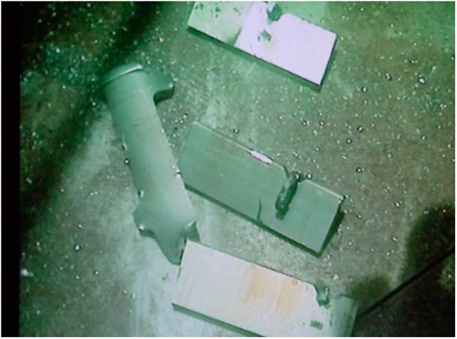
The Radiological Protection Department of CIEMAT (RPD) performed wipe tests over the sample surface and detected 60Co and 241Am contamination. As a result of this, the RPD requested the decontamination of the sample before giving permission to cut the fragments into smaller pieces compatible with dimensions of the leaching containers. The decontamination was performed by dipping the piece in a solution with 2% EDTA in an ultrasonic cleaning bath (35 KHz) for 15 min. The cutting of the pieces was carried out with a cutting machine in a glove box using a silicon carbide disc. A coolant was used to minimize the alteration of the structure of the material in the cutting area. The samples were cut and identified in three directions. 11 pieces were obtained for use in dissolution experiments in order to characterize the pieces, and 4 pieces for leaching experiments. The contact dose rate ranged between 25 and 60 μSv/hr.
Radiological Characterization of Initial Sample
In order to characterize five stainless steel pieces, first it was necessary to dissolve them. The process is shown in Figure 2.
Methodology for the initial steel characterization.
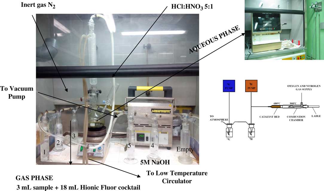
The dissolution of the samples was carried out with a mixture of HCl and HNO3 acids in a ratio 5:1 at 100ºC. The solution was purged with N2 and stirred for four hours, in this step the inorganic carbonaceous fraction was released as CO2 and trapped in washing bottles number 1, 2, and 3 containing 5M NaOH. Other carbonaceous compounds such as CO and CH4, released during the acid stripping, were oxidized in a catalytic furnace to CO2 (using nickel oxide (III)/platinum as a catalyzer and at 200ºC). This CO2 was trapped in washing bottles number 4 and 5, also containing 5M NaOH. Bottle number 1 was discarded due to its acidification and the rest of the washing bottles were collected; in this case, 3 mL of sample was mixed with 18 mL of Hionic Fluor cocktail and 14C analyzed by LSC. To complete the characterization of the initial sample, an aliquot of the solution obtained was introduced in the OX-500 oxidizer, where the sample was combusted to 900ºC in an oxygen stream to constituent water vapor and carbon dioxide; using this process achieved physical separation of 3H and 14C radionuclides into two separate counting vials. The gases formed passed through a catalyst bed (copper oxide [II], platinum and silver vanadate), where the carbon compounds were converted to CO2 that was absorbed in Oxysolve C-400. Instagel Plus was added as the 14C liquid scintillator. Finally, the cocktail vial obtained was analyzed by LSC. The solution obtained in the process was measured by gamma spectrometry to determine the activity of 60Co present in the initial sample.
Leaching Process
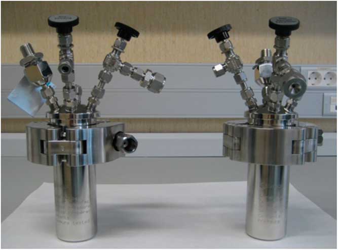
After cutting the sample pieces, the leaching process started with two samples and was performed in high pressure stainless steel reactors with Teflon inserts at room temperature (Figure 3).
High-pressure steel reactors.
The leaching test procedure was based on the standard procedure ISO 6961 (International Organization for Standardization. 1982(E)) and was carried out in the following way:
1. Before using the containers, they were cleaned with ultrapure water and the stainless steel pieces were cleaned with acetone and ultrapure water.
2. The value of the surface area exposed to the leachant was 14E-4 m2. The leach tests were conducted at room temperature and the losses of leachant by vaporization were insignificant.
3. The specimen was suspended in 120 mL of leachant by means of a Teflon thread and surrounded by at least 1 cm of liquid in all directions.
4. NaOH pH=12 and 1M H3PO4 were used as leachants. A synthetic mixture of N2 and O2 (21% oxygen, 79% nitrogen) was introduced in the containers to ensure that the leaching process takes place under aerobic conditions. The pressure vessels were 1 bar.
5. The gas and the leachate were replaced after 14, 28, 56, 90, 180, and 280 days. After each period, first of all the gas samples (volatile species) were collected by means of a gas tight syringe and immediately injected into the GC-MS system.
6. After completing the previous step, the containers were opened, the specimens were removed from the leachant, and the leachates were transferred to a bottle, which were labelled and stored for later analysis.
7. After storing the leachates, the Teflon inserts were rinsed with ultrapure water, refilled with fresh leachant, the specimens immersed in the liquid and after purging with synthetic air, the reactors were closed.
The leachate samples corresponding to all steps were analyzed for 14C with a low background LSC, gamma emitters with a Canberra BEGe 3830 HPGe detector, the gas and leachate volatile species with a GC-MS and the organic dissolved species (carboxylic acids) with an IC system.
RESULTS AND DISCUSSION
Radiological Characterization of the Initial Sample
The results of 14C obtained in the aqueous and gas phase and the total activity of 14C, corresponding to 5 pieces, are shown in Table 3. It is observed that 14C practically remains in the aqueous phase as organic carbon, which is in agreement with the studies carried out by other authors (Hardy et al. Reference Hardy and Gillham1996; Deng et al. Reference Deng, Campbell and Burris1997), who proposed a mechanism of hydrocarbon formation through processes similar to Fischer-Tropsch synthesis.
Results of 14C and 60Co of the stainless steel pieces (reference date April 16, 2017).

The solutions of the samples (aqueous phases) were analyzed by gamma spectrometry and the values of the activities of 60Co are shown in Table 3. The ratio between 14C and 60Co was determined for all samples.
The expanded uncertainty, U, of the results is k*uc, where k=2 is the coverage factor that defines an interval having a level of confidence of approximately 95%, and uc is the combined uncertainty obtained by the law of propagation of uncertainty.
Leaching Process and Speciation Using NaOH pH=12 as Leachant
14C and 60Co Results
The 60Co activity of the sample A-CAST-12 measured by gamma spectrometry, and used for the leaching process, was 6.03E03 Bq/g±6%. This measurement was in the range of the mean value (5.45E03±9.62E2 Bq/g) obtained from the determinations by dissolution of five pieces adjacent to the sample used for this leaching study. In accordance with these data, it was assumed that the 60Co was homogeneously distributed in the piece. Using the ratio between 14C and 60Co, the 14C present in the piece of stainless steel was estimated to be approximately 4 Bq/g.
The results of 14C and 60Co obtained in the different steps, once the leaching process finished, are indicated in Table 4.
Results of 14C and 60Co in the NaOH pH=12 leachate (volume=120 mL).

As the sample weight was 19.4650 g, in 120 mL of leachant, if all carbon were leached, this would lead to 6.62E-01 Bq/mL of 14C. This means that, in the first step (15 days), 3.6% of the total 14C in the piece was leached. Although the value of the first step was higher than limit of quantification (LOQ), the rest of steps were below LOQ.
Results for 60Co were determined for all steps. The amount of stainless steel leached was calculated from 60Co data, since it was assumed 60Co (6.03E3 Bq/g) was homogeneously distributed in the stainless steel piece and that the amount of 60Co present could provide information regarding the amount of 14C present. To calculate the corrosion rate R c (nm/year), an equation used is similar to that used by other authors (Sakuragi et al. Reference Sakuragi, Yoshida, Kato and Tateishi2016a, Reference Sakuragi, Yoshida, Kinugasa, Kato and Tateishi2016b):
 $$R_{{\rm c}} {\equals}{{A_{{{\rm ss}}} \cdot 10^{9} } \over {\rho _{{{\rm ss}}} \cdot t}}$$
where A ss is the cumulative mass amount of stainless steel leached per unit surface area (g/m2), ρ is the stainless steel density (7.9E06 g/m3), and t is the test time (years). The surface area of the sample used in the leaching process was 14E-04 m2. The data for the corrosion rate obtained from cumulative stainless steel leaching versus the time of leaching are shown in the Figure 4.
Corrosion rate of stainless steel leached as a function of time.
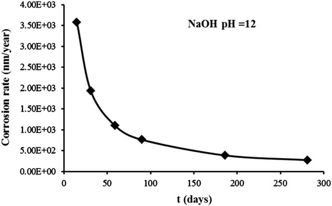
The corrosion rate was estimated to be approximately 274 nm/year after 281 days, and can be considered constant over time. This value is in a good agreement with a determination (100 nm/year) obtained by other authors (Blackwood Reference Blackwood, Gould, Naish, Porter, Rance, Sharland, Smart, Thomas and Yates2002; Kursten Reference Kursten2014), and therefore the level of 60Co will be adequate to calculate the corrosion rate. On the other hand, this value (274 nm/year) obtained in aerobic conditions is higher than the one obtained by Sakuragi et al. (Reference Sakuragi, Yoshida, Kato and Tateishi2016a) (0.4 nm/year) using the hydrogen measurement under the anaerobic condition.
Organic Carbon Compounds Results
∙ Organic carbon dissolved species by ion chromatography
The results of the different leachates are shown in Table 5.
Results obtained in the different steps from NaOH leachates.

As can be observed, all values are less than LOQ, therefore it is not possible to draw any conclusions.
∙ Gas and leachate volatile species by gas chromatography-mass spectrometry
The CO results produced in the different steps of the process are shown in Table 6. Alcohols and aldehydes were not detected in any step of the leaching process.
Results of carbon compounds in NaOH pH=12 leachate (volume=120 mL).

Leaching Process and Speciation Using 1M H3PO4 as Leachant
14 C and 60 Co Results
The 60Co activity of the sample A-CAST-13 measured by gamma spectrometry, and used for the leaching process, was 6.32E03 Bq/g±6%. According with the ratio between 14C and 60Co, the 14C present in the piece of stainless steel would be approximately 4 Bq/g.
The results of 14C and 60Co obtained in the different steps, after the experimental leaching process was finished, are indicated in Table 7. On the other hand, although CO was detected, it was not possible to determine 14C present because a technique to trap the gas samples was not implemented in our laboratories.
Results of 14C and 60Co in the 1M H3PO4 leachate (volume=120 mL).

As the weight of the piece was 19.5389 g, in the 120 mL of leachant, if all carbon were leached, it would lead to 6.97E-01 Bq/mL of 14C. This means that in the first step (15 days), 5.7% of the total 14C in the piece was leached.
The values obtained for the leaching of 14C using both a NaOH or a H3PO4 medium were above the LOQ only at the beginning of the leaching process, and it could be a consequence of 14C distribution in the piece. According to some authors (Sakuragi et al. Reference Sakuragi, Yamashitab, Akagib and Takahashi2016c; Ueda et al. Reference Ueda, Sakuragi, Fujii and Owada2017), in the case of Zircaloy, 14C specific activity in the external oxide layer that might be activated from nitrogen impurity (14N(n,p)14C reaction) and oxygen (17O(n, α)14C reaction) was approximately 3 times higher than that in base Zircaloy.
As before, the results of 60Co were determined. The amount of stainless steel leached was calculated from 60Co data (6.32E03 Bq/g). The corrosion rate (calculated by Equation 1) is approximately 2.01E04 nm/year after 263 days, and this is expected to be constant over time. The data of the corrosion rate obtained from cumulative stainless steel leaching versus the time of leaching are shown in the Figure 5.
Corrosion rate of stainless steel obtained as a function of time.
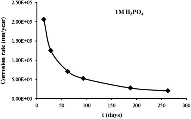
The corrosion rate both in NaOH and H3PO4 aerobic conditions decreases with time to a low value, as observed in Figures 4 and 5. This behavior is similar to the one observed in anaerobic conditions (Smart et al. Reference Smart, Blackwood, Marsh, Naish, O’Brien, Rance and Thomas2004) where there is a built-up a layer of corrosion product that controls the corrosion rate evolution.
Organic Carbon Compounds
∙ Organic carbon dissolved species by ion chromatography
The analyses were performed in the same conditions as mentioned for NaOH leachate. However, in this case it was necessary to dilute the sample to be analyzed due to a high phosphate concentration, which interfered in the signal of oxalate. As a consequence of this prepared dilution, although the LOQ was higher than in the case of NaOH leachate, the oxalate could be measured, since its value was above the LOQ. The results obtained in the different steps of leaching are indicated in Table 8.
Results obtained in the different steps from H3PO4 leachates.

In the first step (14 days) of leaching, oxalate was the compound where 14C was detected (5.7% of the total 14C).
According to the carbon composition data of the 304 Stainless Steel (either 0.035 % C max. or 0.08 % C max.), either 3.6% max. or 1.3% max. of the total carbon was leached respectively.
∙ Gas and leachate volatile species by gas chromatography-mass spectrometry
The analyses were performed in the same conditions as mentioned for NaOH leachate.
The results of CO produced in the different steps of the process are shown in Table 9. Alcohols and aldehydes were not detected in any step of the leaching process. On the other hand, although CO was detected, it was not possible to determine the 14C present, because the technique to trap the gas samples was not implemented in our laboratories.
Results of carbon compounds in H3PO4 leachate (volume=120 mL).

CONCLUSIONS
1. Only the first step of leaching processes presents a value of 14C higher than the LOQ. These values correspond to a 3.6% of total 14C in the case of NaOH and to a 5.7% in the case of H3PO4.
2. The corrosion rate, calculated by 60Co in the experiments with NaOH, was found to be approximately 2.74E02 nm/year after 281 days, whereas in the experiments with H3PO4 the value obtained was 2.01E04 nm/year after 263 days. Both corrosion rates may be constant over time.
3. Oxalate was found as organic carbon dissolved in all steps of the leaching process using H3PO4 as leachant.
4. Neither alcohols nor aldehydes were found in the leachates.
5. CO was determined in the gas phase of the leaching process; the methodology to determine 14C in this kind of sample was not implemented in our laboratories.
ACKNOWLEDGMENTS
The project has received funding from the European Union’s European Atomic Energy Community’s (Euratom) Seventh Framework Programme FP7/2007-2013 under grant agreement no. 604779, the CAST project.


 Open access