


1. Introduction
Additive manufacturing (AM) enables the realization of complex geometries (Reference Tok and FedaiTok & Fedai, 2025) and multifunctional components (Reference Brenner, Dickmann, Helm, Mitteneder, Schlick, Lehmann, Jugert, Nedeljkovic-Groha, Dollinger and MayerhoferBrenner et al., 2025). However, in laser-based powder bed fusion of metals (PBF-LB/M), manufacturing costs rise with geometrical complexity due to the need for additional support structures and post-processing (Reference Lachmayer, Ehlers and LippertLachmayer et al., 2024). Moreover, limitations such as restricted build volumes and requirements regarding the removal of residual powder restrict the maximum dimensions and geometrical complexity of PBF-LB/M components (Reference Reichwein and KirchnerReichwein & Kirchner, 2021). An effective way to improve economic efficiency and to overcome manufacturing constraints is the use of a differential design approach within a hybrid manufacturing framework. This involves decomposing a geometrically complex component into subcomponents that are easier to manufacture additively, which are subsequently joined to reconstitute the original structure (Reference Reichwein, Geis, Rudolph and KirchnerReichwein et al., 2022).
Adhesive bonding is a well-suited joining process for AM components, as it imposes minimal constraints on the geometry or the material of the adherends (R.D.S.G. Campilho, 2025). To ensure structural integrity, adhesive joints must provide sufficient bonding surface area, and the adhesive should be subjected to shear rather than peel stress (Reference Akkasali, Biswas, Sen and AnithaAkkasali et al., 2024). Numerous studies have explored ways to leverage the geometric design freedom of AM processes to improve the bond strength of adhesive joints. These approaches include the incorporation of lattice structures (Reference Freund, Koch, Watschke, Stammen, Vietor and DilgerFreund et al., 2021), as well as grooved (Reference Moritz, Götze, Schiefer, Stepien, Klotzbach, Standfuß, López, Brückner and LeyensMoritz et al., 2021), sawtooth-shaped (Reference Spaggiari and DentiSpaggiari & Denti, 2021), or auxetically structured (Reference Kemiklioğlu, Demir and YükselKemiklioğlu et al., 2024) bonding surfaces. Since these studies have focused on lap joints between AM components and conventionally manufactured adherends, the scope of optimization has been limited to the bonding surface of the AM part, thereby falling short of the potential achievable through complementary shape optimization of the bonding surfaces of multiple AM adherends. Furthermore, lap joints are hardly suitable for joining of AM subcomponents, as achieving adequate overlap requires the utilization of additional substrate volume, which increases the dimensions of the individual subcomponents, substantially limiting the design potential of hybrid-manufactured structures. While butt joints (BJs) offer only a small bonding surface and are prone to high peel stresses, the performance of scarf joints (SJs) depends on the scarf angle (Reference Ribeiro, Campilho and RochaRibeiro et al., 2025). A larger scarf angle reduces peel stress and enlarges the bonding surface area, at the cost of an increased substrate volume. Whereas conventionally manufactured SJs are tapered only in one or two planes, the design freedom offered by AM enables the realization of a three-dimensional (3D) scarf geometry which is generated on the planar bonding surface of the positive and imprinted complementarily into the bonding surface of the negative adherend (Reference Ascher and SpäthAscher & Späth, 2024).
The objective of this paper is to quantify a 3D SJ concept designed to maximize bond strength and minimize substrate volume, enabling to increase manufacturing efficiency and enhance design freedom through hybrid manufacturing. Since the triangular pyramid (tetrahedron) provides a superior ratio of lateral surface (bonding surface) to base surface area compared to other scarf geometries (e.g., square pyramid, cone), geometry samples featuring positive and negative PBF-LB/M pyramids made of AlSi10Mg and Ti6Al4V were manufactured and geometrically measured (Section 2). The comparison between nominal and actual dimensions was used to derive measures for improved accuracy of fit between positive and negative pyramids (Section 3). Finally, bonded samples were subjected to static tensile tests to compare the bond strength of 3D SJs with that of 1D SJs and BJs (Section 4).
2. Geometric measurement of pyramid geometry samples
Depending on the manufacturing system, process parameters, and materials used, components produced by PBF-LB/M are subject to constraints such as limited dimensional accuracy and increased surface roughness, which negatively affect the accuracy of fit between positive and negative pyramids. To quantify these manufacturing constraints, PBF-LB/M geometry samples made of aluminium alloy AlSi10Mg and titanium alloy Ti6Al4V were geometrically measured. The nominal dimensions of the examined pyramids, the manufacturing process, the measuring equipment and evaluation methods are described in Section 2.1. A comparison of nominal and actual dimensions, along with an analysis of surface roughness, is presented in Section 2.2.
2.1. Materials and methods
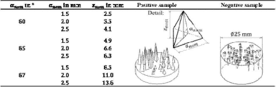
The pyramids featured by the geometry samples exhibit varying nominal scarf angles
 $${\alpha _{nom}} \in \left\{ {80^\circ ;85^\circ ;87^\circ \} } \right.$$
and nominal base edge lengths
$${\alpha _{nom}} \in \left\{ {80^\circ ;85^\circ ;87^\circ \} } \right.$$
and nominal base edge lengths
 $${a_{nom}} \in \left\{ {1.5\;{\rm{mm}};2.0\;{\rm{mm}};2.5\;{\rm{mm}}\} } \right.$$
(Table 1, left). For geometrical measurement, a computer tomograph (VTOME XL 300) with a voxel size of
$${a_{nom}} \in \left\{ {1.5\;{\rm{mm}};2.0\;{\rm{mm}};2.5\;{\rm{mm}}\} } \right.$$
(Table 1, left). For geometrical measurement, a computer tomograph (VTOME XL 300) with a voxel size of
 $$12\;{\rm{\mu m}}$$
was used, resulting in a surface mesh representation of the geometry samples with an average mesh edge length of
$$12\;{\rm{\mu m}}$$
was used, resulting in a surface mesh representation of the geometry samples with an average mesh edge length of
 $$12.6\;{\rm{\mu m}}$$
. For statistical reasons, three pyramids with identical nominal dimensions were placed on each geometry sample, each rotated by
$$12.6\;{\rm{\mu m}}$$
. For statistical reasons, three pyramids with identical nominal dimensions were placed on each geometry sample, each rotated by
 $$120^\circ $$
around the pyramid’s vertical axis (Table 1, right).
$$120^\circ $$
around the pyramid’s vertical axis (Table 1, right).
Nominal dimensions (left) and geometrical features (right) of PBF-LB/M geometry samples featuring positive and negative pyramids made of AlSi10Mg and Ti6Al4V

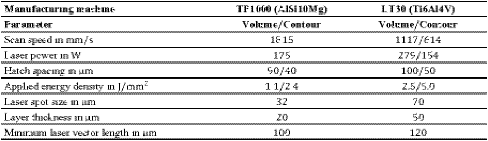
The geometry samples made of AlSi10Mg were manufactured in an upright orientation (pyramid vertical axis parallel to the build direction) using a Trumpf TruPrint 1000 (TP1000) PBF-LB/M machine and metal powder with a particle size between
 $$20$$
and
$$20$$
and
 $$63\;{\rm{\mu m}}$$
(Eckart EN-AC 43000). The Ti6Al4V geometry samples were manufactured in identical build orientation using a DMG Mori Lasertec 30 (LT30) PBF-LB/M machine and metal powder with a particle size between
$$63\;{\rm{\mu m}}$$
(Eckart EN-AC 43000). The Ti6Al4V geometry samples were manufactured in identical build orientation using a DMG Mori Lasertec 30 (LT30) PBF-LB/M machine and metal powder with a particle size between
 $$15$$
and
$$15$$
and
 $$53\;{\rm{\mu m}}$$
(Tekna Ti64-53/15-CS1). The corresponding process parameters are listed in Table 2.
$$53\;{\rm{\mu m}}$$
(Tekna Ti64-53/15-CS1). The corresponding process parameters are listed in Table 2.
Manufacturing machines and parameters used to produce PBF-LB/M geometry samples

To determine the actual mounting height z, the distance between the highest/lowest point of a positive/negative pyramid and a reference plane was measured. The reference plane was defined as a best-fit plane based on the topography of the planar upper surface of the geometry sample using the method of least squares. Accordingly, each pyramid yields a single measurement value characterizing the actual mounting height z. The actual base edge length
 $$a$$
was determined by similarly defining three auxiliary planes on the lateral surfaces of the pyramids and intersecting them with the reference plane. The intersection points of the resulting cut lines describe the vertices of the equilateral triangle at the base of the pyramid. By measuring the distances between these vertices, three measurement values per pyramid were obtained, characterizing the actual base edge length a. The acute supplementary angles between the three auxiliary planes and the reference plane define the actual scarf angle α, again providing three measurement values per pyramid. The surface roughness of the PBF-LB/M pyramids was characterized using the maximum profile peak height
$$a$$
was determined by similarly defining three auxiliary planes on the lateral surfaces of the pyramids and intersecting them with the reference plane. The intersection points of the resulting cut lines describe the vertices of the equilateral triangle at the base of the pyramid. By measuring the distances between these vertices, three measurement values per pyramid were obtained, characterizing the actual base edge length a. The acute supplementary angles between the three auxiliary planes and the reference plane define the actual scarf angle α, again providing three measurement values per pyramid. The surface roughness of the PBF-LB/M pyramids was characterized using the maximum profile peak height
 $${S_P}$$
, which represents the distance between the highest elevation of the lateral pyramid surfaces and the corresponding auxiliary planes.
$${S_P}$$
, which represents the distance between the highest elevation of the lateral pyramid surfaces and the corresponding auxiliary planes.
2.2. Results and discussion
Figures 1 and 2 depict the relative deviations of the actual base edge lengths a, and the actual mounting heights
 $$z$$
of positive and negative pyramids from their respective nominal values as a function of the nominal base edge length
$$z$$
of positive and negative pyramids from their respective nominal values as a function of the nominal base edge length
 $${a_{nom}}$$
. A graphical presentation of the deviations between actual and nominal scarf angles was omitted, as these deviations were negligibly small (
$${a_{nom}}$$
. A graphical presentation of the deviations between actual and nominal scarf angles was omitted, as these deviations were negligibly small (
 $$\!\le 1.1\;\% $$
). The plotted data points represent the arithmetic means of the relative deviations, calculated from
$$\!\le 1.1\;\% $$
). The plotted data points represent the arithmetic means of the relative deviations, calculated from
 $$n = 9$$
measurement values for
$$n = 9$$
measurement values for
 $$a$$
and
$$a$$
and
 $$n = 3$$
measurement values for
$$n = 3$$
measurement values for
 $$z$$
per data point. The shaded areas indicate the positive and negative standard deviation.
$$z$$
per data point. The shaded areas indicate the positive and negative standard deviation.
Relative deviations between actual and nominal base edge lengths of PBF-LB/M pyramids with nominal scarf angles of
 $$80^\circ $$
(left),
$$80^\circ $$
(left),
 $$85^\circ $$
(middle) and
$$85^\circ $$
(middle) and
 $$87^\circ $$
(right)
$$87^\circ $$
(right)

Figure 1 Long description
Three line graphs depict the relative deviations between actual and nominal base edge lengths of PBF-LB/M pyramids with nominal scarf angles of 80 degrees (left), 85 degrees (middle), and 87 degrees (right). Each graph has the nominal base edge length (a_nom) in millimeters on the horizontal axis, ranging from 1.5 to 2.5 millimeters, and the relative deviation ((a/a_nom) - 1) in percent on the vertical axis, ranging from -10 percent to 5 percent. The graphs compare two materials: AlSi10Mg and Ti6Al4V, each with negative and positive pyramids. AlSi10Mg negative pyramids are represented by red squares, AlSi10Mg positive pyramids by blue squares, Ti6Al4V negative pyramids by red circles, and Ti6Al4V positive pyramids by blue circles. The shaded areas around the lines indicate the variability or uncertainty in the measurements. In all three graphs, the relative deviations for AlSi10Mg positive pyramids (blue squares) are generally higher than those for AlSi10Mg negative pyramids (red squares), Ti6Al4V positive pyramids (blue circles), and Ti6Al4V negative pyramids (red circles). As the nominal scarf angle increases from 80 degrees to 87 degrees, the relative deviations for all pyramid types tend to decrease slightly.
Relative deviations between actual and nominal mounting heights of PBF-LB/M pyramids with nominal scarf angles of
 $$80^\circ $$
(left),
$$80^\circ $$
(left),
 $$85^\circ $$
(middle) and
$$85^\circ $$
(middle) and
 $$87^\circ $$
(right)
$$87^\circ $$
(right)

The relative deviations of the base edge lengths decrease with increasing nominal base edge length, with negative pyramids exhibiting larger deviations than positive ones. The nominal scarf angle has no discernible effect on these deviations. For identical nominal geometries, positive pyramids exhibit larger actual base edge lengths than negative pyramids (
 $${a_ - } \lt {a_{nom}} \lt {a_ + }$$
).
$${a_ - } \lt {a_{nom}} \lt {a_ + }$$
).
For both positive and negative pyramids, the actual mounting heights remain below the nominal values. The deviations increase as the nominal base edge length decreases, with negative pyramids showing larger deviations than the positive pyramids (
 $${z_ - } \lt {z_ + } \lt {z_{nom}}$$
). For positive AlSi10Mg pyramids, the scarf angle has no influence on the deviations of the actual mounting heights. In contrast, for positive Ti6Al4V pyramids, the deviations double between
$${z_ - } \lt {z_ + } \lt {z_{nom}}$$
). For positive AlSi10Mg pyramids, the scarf angle has no influence on the deviations of the actual mounting heights. In contrast, for positive Ti6Al4V pyramids, the deviations double between
 $${\alpha _{nom}} = 80^\circ $$
(Figure 2, left) and
$${\alpha _{nom}} = 80^\circ $$
(Figure 2, left) and
 $$87^\circ $$
(Figure 2, right) reaching up to
$$87^\circ $$
(Figure 2, right) reaching up to
 $$ - 15\% $$
. For negative pyramids, the scarf angle has a strong effect on the deviations for both Ti6Al4V and AlSi10Mg pyramids. Between
$$ - 15\% $$
. For negative pyramids, the scarf angle has a strong effect on the deviations for both Ti6Al4V and AlSi10Mg pyramids. Between
 $${\alpha _{nom}} = 80^\circ $$
(Figure 2, left) and
$${\alpha _{nom}} = 80^\circ $$
(Figure 2, left) and
 $$85^\circ $$
(Figure 2, middle), the increase in deviations is moderate, with extreme values rising from
$$85^\circ $$
(Figure 2, middle), the increase in deviations is moderate, with extreme values rising from
 $$ - 27\% $$
to
$$ - 27\% $$
to
 $$ - 30\% $$
(AlSi10Mg) and from
$$ - 30\% $$
(AlSi10Mg) and from
 $$ - 23\% $$
to
$$ - 23\% $$
to
 $$ - 26\% $$
(Ti6Al4V). However, at
$$ - 26\% $$
(Ti6Al4V). However, at
 $${\alpha _{nom}} = 87^\circ $$
(Figure 2, right) the deviations increase disproportionately, reaching up to
$${\alpha _{nom}} = 87^\circ $$
(Figure 2, right) the deviations increase disproportionately, reaching up to
 $$ - 38\% $$
(AlSi10Mg) and
$$ - 38\% $$
(AlSi10Mg) and
 $$ - 53\% $$
(Ti6Al4V).
$$ - 53\% $$
(Ti6Al4V).
The deviation behavior can be attributed to the thermal characteristics of the PBF-LB/M process. At small geometric feature sizes, part contours are scanned with compact laser paths of short vector lengths, resulting in locally increased heat input. Although the selected hatch spacing (see Table 1) partially compensates for this effect, it does not fully meet the locally varying melt pool dimensions. As a result, melt flow beyond the nominal contour leads to a reduced base edge length of negative pyramids and an increased base edge length of positive pyramids. For the same reason, the actual mounting heights of positive pyramids are systematically larger than those of their negative counterparts. Close to the pyramid tip, the melt pool dimension approaches the scale of the scan vectors, preventing the formation of sharply defined part contours. In positive pyramids, this leads to a continued increase in mounting height, while the pyramid contours progressively transition towards a cylindrical shape. In negative pyramids, the melt can entirely cover the part contour, leading to a reduction in negative mounting height. This effect is further amplified in Ti6Al4V due to the higher energy density (see Table 1).
The profile peak height
 $${S_P}$$
at the lateral pyramid surfaces decreases with increasing scarf angle, with maximum values of
$${S_P}$$
at the lateral pyramid surfaces decreases with increasing scarf angle, with maximum values of
 $${S_P} = 141\;{\rm{\mu m}}$$
(AlSi10Mg) and
$${S_P} = 141\;{\rm{\mu m}}$$
(AlSi10Mg) and
 $${S_P} = 180\;{\rm{\mu m}}$$
(Ti6Al4V) at
$${S_P} = 180\;{\rm{\mu m}}$$
(Ti6Al4V) at
 $${\alpha _{nom}} = 80^\circ $$
.
$${\alpha _{nom}} = 80^\circ $$
.
3. Measures for improved accuracy of fit
The dimensional discrepancies between the actual base edge lengths of positive and negative pyramids (
 $${a_ - } \lt {a_{nom}} \lt {a_ + }$$
), the limited manufacturing resolution at the pyramid tips (
$${a_ - } \lt {a_{nom}} \lt {a_ + }$$
), the limited manufacturing resolution at the pyramid tips (
 $${z_ - } \lt {z_ + } \lt {z_{nom}}$$
), and the high surface roughness of the lateral pyramid surfaces (
$${z_ - } \lt {z_ + } \lt {z_{nom}}$$
), and the high surface roughness of the lateral pyramid surfaces (
 $${S_p} \gt 50\;{\rm{\mu m}}$$
) restrict the accuracy of fit between positive and negative PBF-LB/M pyramids. If the adherends cannot be fully engaged, bonding surface area and joint precision are reduced. Accordingly, design and manufacturing measures to improve the accuracy of fit were derived from the deviations between actual and nominal pyramid geometries. The resulting measures and the associated challenges are summarized in Figure 3.
$${S_p} \gt 50\;{\rm{\mu m}}$$
) restrict the accuracy of fit between positive and negative PBF-LB/M pyramids. If the adherends cannot be fully engaged, bonding surface area and joint precision are reduced. Accordingly, design and manufacturing measures to improve the accuracy of fit were derived from the deviations between actual and nominal pyramid geometries. The resulting measures and the associated challenges are summarized in Figure 3.
Design and manufacturing challenges (top) affecting the accuracy of fit between positive and negative PBF-LB/M pyramids, with corresponding measures for improvement (bottom)

Figure 3 Long description
Panel A: A triangle representing accuracy challenges with labels indicating nominal, upper, and lower bounds for the gap. Panel B: A curve representing resolution challenges with labels indicating nominal, upper, and lower bounds for resolution. Panel C: A triangle with a detailed surface representing surface roughness challenges, with a sphere indicating a roughness threshold. Panel D: A triangle representing allowance measures for accuracy, showing reduced gap. Panel E: A curve representing allowance measures for resolution, showing reduced bounds. Panel F: A triangle with a smoothed surface representing surface smoothing measures, with a label indicating a smoothness threshold.
For all investigated nominal base edge lengths
 $${a_{nom}}$$
, the actual base edge length of positive pyramids (
$${a_{nom}}$$
, the actual base edge length of positive pyramids (
 $${a_ + }$$
) is smaller than that of the negative pyramids (
$${a_ + }$$
) is smaller than that of the negative pyramids (
 $${a_ - }$$
), preventing full engagement of positive and negative pyramids (Figure 3, top left). This incomplete fit leads to a reduction of the actual bonding surface area (decreasing bond strength) and gap formation between the adherends (compromising joint precision). To mitigate gap formation, the nominal base edge length of positive pyramids (
$${a_ - }$$
), preventing full engagement of positive and negative pyramids (Figure 3, top left). This incomplete fit leads to a reduction of the actual bonding surface area (decreasing bond strength) and gap formation between the adherends (compromising joint precision). To mitigate gap formation, the nominal base edge length of positive pyramids (
 $${a_{nom, + }}$$
) can be reduced relative to
$${a_{nom, + }}$$
) can be reduced relative to
 $${a_{nom, - }} = {a_{nom}}$$
according to Equation 1. Here,
$${a_{nom, - }} = {a_{nom}}$$
according to Equation 1. Here,
 $${{\rm{\beta }}_0}$$
and
$${{\rm{\beta }}_0}$$
and
 $${{\rm{\beta }}_1}$$
denote the regression coefficients obtained from a linear regression analysis
$${{\rm{\beta }}_1}$$
denote the regression coefficients obtained from a linear regression analysis
 $$\left( {{{\rm{R}}^2} \gt 0,99} \right)$$
of the dependent variable
$$\left( {{{\rm{R}}^2} \gt 0,99} \right)$$
of the dependent variable
 against the independent variable
 $${a_{nom}} = {a_{nom, - }}$$
.
$${a_{nom}} = {a_{nom, - }}$$
.

As the scarf angle exerts only a negligible influence on the relative deviations, the regression coefficients obtained at
 $$87^\circ $$
can be considered valid for all scarf angles within the investigated range. Consequently, by adjusting the nominal base edge length of positive pyramids
$$87^\circ $$
can be considered valid for all scarf angles within the investigated range. Consequently, by adjusting the nominal base edge length of positive pyramids
 $${a_{nom, + }}$$
according to Equation 1, the actual base edge lengths of positive and negative pyramids can be well aligned (
$${a_{nom, + }}$$
according to Equation 1, the actual base edge lengths of positive and negative pyramids can be well aligned (
 $${a_ + } \approx {a_ - }$$
according to Figure 3, bottom left).
$${a_ + } \approx {a_ - }$$
according to Figure 3, bottom left).
The actual mounting height of negative pyramids (
 $${z_ - }$$
) is lower than that of positive pyramids (
$${z_ - }$$
) is lower than that of positive pyramids (
 $${z_ + }$$
). This likewise leads to gap formation between the adherends and an increased adhesive fill gap thickness (Figure 3, top middle). Due to the reduced manufacturing resolution associated with negative part contours, achieving an ideal accuracy of fit (
$${z_ + }$$
). This likewise leads to gap formation between the adherends and an increased adhesive fill gap thickness (Figure 3, top middle). Due to the reduced manufacturing resolution associated with negative part contours, achieving an ideal accuracy of fit (
 $${z_ + } \approx {z_ - }$$
) requires reducing the nominal mounting height of the positive pyramids
$${z_ + } \approx {z_ - }$$
) requires reducing the nominal mounting height of the positive pyramids
 $${z_{nom, + }}$$
relative to
$${z_{nom, + }}$$
relative to
 $${z_{nom, - }} = {z_{nom}}$$
. To maintain a constant scarf angle
$${z_{nom, - }} = {z_{nom}}$$
. To maintain a constant scarf angle
 $$\alpha $$
,
$$\alpha $$
,
 $${z_{nom, + }}$$
(Equation 2) represents the nominal mounting height of a truncated pyramid with
$${z_{nom, + }}$$
(Equation 2) represents the nominal mounting height of a truncated pyramid with
 $$\alpha = {\alpha _{nom}}$$
. Omitting the pyramid tips increases the minimum geometric feature size, and the deviations between nominal and actual mounting heights are therefore expected to be negligible (
$$\alpha = {\alpha _{nom}}$$
. Omitting the pyramid tips increases the minimum geometric feature size, and the deviations between nominal and actual mounting heights are therefore expected to be negligible (
 $${z_ + } \approx {z_{{{nom}}, + }}$$
). The regression coefficients
$${z_ + } \approx {z_{{{nom}}, + }}$$
). The regression coefficients
 $${{\rm{\beta }}_0}$$
and
$${{\rm{\beta }}_0}$$
and
 $${{\rm{\beta }}_1}$$
were obtained from a linear regression analysis
$${{\rm{\beta }}_1}$$
were obtained from a linear regression analysis
 $$( {{{\rm{R}}^2} \gt 0,\!99} )$$
of the dependent variable
$$( {{{\rm{R}}^2} \gt 0,\!99} )$$
of the dependent variable
 $${z_{nom, + }}\; \raise -1pt{\mathop {=} \limits ^{\rm def}} \;{z_ - }$$
against the independent variable
$${z_{nom, + }}\; \raise -1pt{\mathop {=} \limits ^{\rm def}} \;{z_ - }$$
against the independent variable
 $${a_{nom}} = {a_{nom, - }}$$
.
$${a_{nom}} = {a_{nom, - }}$$
.
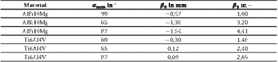
 $${z_{nom, + }}\;\raise -1pt{\mathop {=} \limits ^{\rm def}} \;{z_ - } \approx {\beta _0} + {\beta _1}{a_{nom}}\quad\quad\quad\quad\quad\quad\quad\quad\quad\quad\quad\quad\quad $$
 $${\beta _0} \;{\rm and}\; {\beta _1}\; {\rm for}\;1.5\;{\rm{mm}} \le {a_{nom}} \le 2.5\;{\rm{mm}}\; {\rm according\; to\; Table\; 3} $$
Regression Coefficients
 $${\beta _0}$$
and
$${\beta _0}$$
and
 $${\beta _1}$$
used to determine the nominal mounting height
$${\beta _1}$$
used to determine the nominal mounting height
 $${z_{nom, + }}$$
of a truncated positive pyramid in accordance with Equation 2
$${z_{nom, + }}$$
of a truncated positive pyramid in accordance with Equation 2

Consequently, by adjusting the nominal mounting height of positive pyramids
 $${z_{nom, + }}$$
according to Equation 2 (using
$${z_{nom, + }}$$
according to Equation 2 (using
 $${z_{nom, - }} = {z_{nom}}$$
), the actual mounting heights of positive and negative pyramids can be matched closely (
$${z_{nom, - }} = {z_{nom}}$$
), the actual mounting heights of positive and negative pyramids can be matched closely (
 $${z_ + } \approx {z_ - }$$
according to Figure 3, bottom middle).
$${z_ + } \approx {z_ - }$$
according to Figure 3, bottom middle).
If the positive and negative pyramids exhibit identical base edge lengths (
 $${a_ + } = {a_ - }$$
), scarf angles (
$${a_ + } = {a_ - }$$
), scarf angles (
 $${\alpha _ + } = {\alpha _ - }$$
), and mounting heights (
$${\alpha _ + } = {\alpha _ - }$$
), and mounting heights (
 $${z_ + } = {z_ - }$$
), the maximum profile peak height
$${z_ + } = {z_ - }$$
), the maximum profile peak height
 $${S_p}$$
of the lateral pyramid surfaces defines the minimum achievable adhesive fill gap thickness
$${S_p}$$
of the lateral pyramid surfaces defines the minimum achievable adhesive fill gap thickness
 $${h_{min}}$$
(Figure 3, top right). Since many structural adhesives exhibit optimal strength for
$${h_{min}}$$
(Figure 3, top right). Since many structural adhesives exhibit optimal strength for
 $$h \geq 0.05\;{\rm{mm}}$$
, the maximum profile peak height of the pyramid lateral surfaces should satisfy the condition
$$h \geq 0.05\;{\rm{mm}}$$
, the maximum profile peak height of the pyramid lateral surfaces should satisfy the condition
 $${S_p} \le 50\;{\rm{\mu m}}$$
(Figure 3, bottom right). Abrasive blasting with glass beads is a suitable post-processing method for reducing the surface roughness of the lateral pyramid surfaces, owing to the adjustable abrasiveness and fine grain size of the blasting medium. By abrasive blasting of the AlSi10Mg and Ti6Al4V geometry samples with glass beads (grain size
$${S_p} \le 50\;{\rm{\mu m}}$$
(Figure 3, bottom right). Abrasive blasting with glass beads is a suitable post-processing method for reducing the surface roughness of the lateral pyramid surfaces, owing to the adjustable abrasiveness and fine grain size of the blasting medium. By abrasive blasting of the AlSi10Mg and Ti6Al4V geometry samples with glass beads (grain size
 $$200$$
to
$$200$$
to
 $$300\;{\rm{\mu m}}$$
) at a pressure of
$$300\;{\rm{\mu m}}$$
) at a pressure of
 $$4.5\;{\rm{bar}}$$
, the condition
$$4.5\;{\rm{bar}}$$
, the condition
 $${S_p} \le 50\;{\rm{\mu m}}$$
was met for all investigated scarf angles. The resulting maximum profile peak heights of the lateral pyramid surfaces after blasting are
$${S_p} \le 50\;{\rm{\mu m}}$$
was met for all investigated scarf angles. The resulting maximum profile peak heights of the lateral pyramid surfaces after blasting are
 $${S_p} = 35\;{\rm{\mu m}}$$
(AlSi10Mg) und
$${S_p} = 35\;{\rm{\mu m}}$$
(AlSi10Mg) und
 $${S_p} = 48\;{\rm{\mu m}}$$
(Ti6Al4V) at
$${S_p} = 48\;{\rm{\mu m}}$$
(Ti6Al4V) at
 $${\alpha _{nom}} = 80^\circ $$
.
$${\alpha _{nom}} = 80^\circ $$
.
4. Static tensile tests
To evaluate the influence of bonding surface topography on bond strength, static tensile tests were performed on adhesively bonded butt joints (BJs), 1D scarf joints (1D SJs), and 3D scarf joints (3D SJs). The adherend geometry, manufacturing process, and testing parameters are detailed in Section 4.1, while the results are presented in Section 4.2.
4.1. Materials and methods
The static tensile tests were performed in accordance with DIN EN 15870:2009-08. The tensile samples consisted of either two PBF-LB/AlSi10Mg or two PBF-LB/Ti6Al4V cylinders with a nominal outer diameter of
 $${D_{nom}} = 10\,{\rm{mm}}$$
, which were bonded using a two-component epoxy-based structural adhesive (3M Scotch-Weld DP490). The topography of the bonding surfaces was designed as planar (
$${D_{nom}} = 10\,{\rm{mm}}$$
, which were bonded using a two-component epoxy-based structural adhesive (3M Scotch-Weld DP490). The topography of the bonding surfaces was designed as planar (
 $${\alpha _{nom}} = 0^\circ $$
), 1D-scarfed (
$${\alpha _{nom}} = 0^\circ $$
), 1D-scarfed (
 $${\alpha _{nom}} = 70^\circ /75^\circ $$
), or 3D-scarfed (
$${\alpha _{nom}} = 70^\circ /75^\circ $$
), or 3D-scarfed (
 $${\alpha _{nom}} = 75^\circ /80^\circ /85^\circ )$$
.
$${\alpha _{nom}} = 75^\circ /80^\circ /85^\circ )$$
.
For the 3D SJs, two configurations were investigated: a standard configuration (SC) and a manufacturing-optimized configuration (MOC). In SC, the pyramids were arranged edge-to-edge on the end face of the cylinder, with positive and negative pyramids featuring identical nominal base edge lengths
 $${a_{nom}} = {a_{nom, + }} = {a_{nom, - }} = 1.5\,{\rm{mm}}$$
and nominal mounting heights
$${a_{nom}} = {a_{nom, + }} = {a_{nom, - }} = 1.5\,{\rm{mm}}$$
and nominal mounting heights
 $${z_{nom}} = {z_{nom, + }} = {z_{nom, - }} = f( {{a_{nom}},{\alpha _{nom}}} )$$
. The selection of
$${z_{nom}} = {z_{nom, + }} = {z_{nom, - }} = f( {{a_{nom}},{\alpha _{nom}}} )$$
. The selection of
 $${a_{nom}} = 1.5\;{\rm{mm}}$$
ensured a minimum nominal mounting height among the pyramid geometries considered in Section 2., while maintaining the same nominal bonding surface area as 1D or other 3D SJs with an identical scarf angle. In MOC, the measures for improved accuracy of fit described in Section 3 were implemented. Accordingly, the scarf geometry of the positive adherend was manufactured as a truncated pyramid with a reduced nominal base edge length of
$${a_{nom}} = 1.5\;{\rm{mm}}$$
ensured a minimum nominal mounting height among the pyramid geometries considered in Section 2., while maintaining the same nominal bonding surface area as 1D or other 3D SJs with an identical scarf angle. In MOC, the measures for improved accuracy of fit described in Section 3 were implemented. Accordingly, the scarf geometry of the positive adherend was manufactured as a truncated pyramid with a reduced nominal base edge length of
 $${a_{nom, + }} = 1.30\,{\rm{mm}}$$
according to Equation 1 and a reduced nominal mounting height
$${a_{nom, + }} = 1.30\,{\rm{mm}}$$
according to Equation 1 and a reduced nominal mounting height
 $${z_{nom, + }} = f( {{a_{nom}},{\alpha _{nom}}})$$
according to Equation 2. The negative adherend retained a regular pyramid geometry with
$${z_{nom, + }} = f( {{a_{nom}},{\alpha _{nom}}})$$
according to Equation 2. The negative adherend retained a regular pyramid geometry with
 $${a_{nom, - }} = {a_{nom}} = 1.5\,{\rm{mm}}$$
and
$${a_{nom, - }} = {a_{nom}} = 1.5\,{\rm{mm}}$$
and
 $${z_{nom, - }} = {z_{nom}} = f( {{a_{nom}},{\alpha _{nom}}} )$$
.
$${z_{nom, - }} = {z_{nom}} = f( {{a_{nom}},{\alpha _{nom}}} )$$
.
An additional manufacturing constraint arises when multiple adjacent pyramids are produced. In an edge-to-edge arrangement of negative pyramids, the wall thickness separating individual cavities decreases to a critical minimum at the pyramid base, leading to a local increase in energy density and a widening of the melt pool. Both effects further reduce the actual mounting height and base edge length of the negative pyramids. To mitigate these effects and improve the accuracy of fit, a minimum spacing between adjacent pyramids was maintained, corresponding to a multiple of the melt pool width (Reference Gibson, Rosen, Stucker and KhorasaniGibson et al., 2021). Based on the hatch spacing provided in Table 1, the spacing was set to
 $$240\;{\rm{\mu m}}$$
for AlSi10Mg and
$$240\;{\rm{\mu m}}$$
for AlSi10Mg and
 $$300\;{\rm{\mu m}}$$
for Ti6Al4V pyramids in MOC. Additionally, incomplete pyramids along the cylinder contour were excluded, and the nominal cylinder diameter was reduced to
$$300\;{\rm{\mu m}}$$
for Ti6Al4V pyramids in MOC. Additionally, incomplete pyramids along the cylinder contour were excluded, and the nominal cylinder diameter was reduced to
 $${D_{nom}} = 8.1\,{\rm{mm}}$$
. The different adherend configurations are compared in Figure 4.
$${D_{nom}} = 8.1\,{\rm{mm}}$$
. The different adherend configurations are compared in Figure 4.
Nominal Dimensions and number of bonded tensile samples
 $$n$$
(left) with varying adherend configurations (right)
$$n$$
(left) with varying adherend configurations (right)

Figure 4 Long description
The table compares nominal dimensions and the number of bonded tensile samples for different adherend configurations. It has three main sections: Butt Joint (BJ), 1D Scarf Joint (1D SJ), and 3D Scarf Joint (3D SJ). Each section lists the nominal angle, nominal depth, and the number of samples for different materials. The materials include AlSi10Mg and Ti6Al4V. The table provides specific values for each configuration and material. For example, in the Butt Joint section, AlSi10Mg has 14 samples at a nominal angle of 0 degrees, while Ti6Al4V has 6 samples at the same angle. The 1D Scarf Joint section lists values for nominal angles of 70 and 75 degrees, with varying depths and sample numbers for each material. The 3D Scarf Joint section includes nominal angles of 75, 80, and 85 degrees, with different depths and sample numbers for each material and configuration. The table also includes a visual representation of the square alignment base and the different joint configurations.
The adherends were manufactured in an upright orientation using the machines and process parameters described in Section 2.1. After printing, the MOC adherends were surface treated by abrasive blasting with glass beads (grain size
 $$200$$
to
$$200$$
to
 $$300\;{\rm{\mu m}}$$
) at a pressure of
$$300\;{\rm{\mu m}}$$
) at a pressure of
 $$4.5\;{\rm{bar}}$$
. All adherends were then cleaned in an ultrasonic bath with isopropyl and rinsed with deionized water. A custom fixture was used to ensure precise alignment of the adherends during bonding. The fixture consists of a 90° prism, in which the cylinders are placed on their lateral surfaces with bearing blocks attached to a square alignment base (
$$4.5\;{\rm{bar}}$$
. All adherends were then cleaned in an ultrasonic bath with isopropyl and rinsed with deionized water. A custom fixture was used to ensure precise alignment of the adherends during bonding. The fixture consists of a 90° prism, in which the cylinders are placed on their lateral surfaces with bearing blocks attached to a square alignment base (
 $$\square\; {\rm{}}6\;{\rm{mm}}$$
). One bearing block is fixed to the prism, while the other can be adjusted using a micrometer screw. The longitudinal spacing between then adherends
$$\square\; {\rm{}}6\;{\rm{mm}}$$
). One bearing block is fixed to the prism, while the other can be adjusted using a micrometer screw. The longitudinal spacing between then adherends
 $${z_{LS}}$$
was set to achieve a nominal adhesive fill gap thickness of
$${z_{LS}}$$
was set to achieve a nominal adhesive fill gap thickness of
 $${h_{nom}} = 50\;{\rm{\mu m}}$$
(Equation 3).
$${h_{nom}} = 50\;{\rm{\mu m}}$$
(Equation 3).
 $${z_{LS}} = {h_{nom}}/\cos {\alpha _{nom}}$$
Due to variations in surface roughness and the accuracy of fit, the actual adhesive fill gap thickness varies between joint configurations. For BJs, 1D SJs, and 3D SJs in MOC the actual fill gap thickness ranged from
 $$50$$
to
$$50$$
to
 $$100\;{\rm{\mu m}}$$
, whereas for 3D SJs in SC,
$$100\;{\rm{\mu m}}$$
, whereas for 3D SJs in SC,
 applies. After joining, excess adhesive was manually removed and the aligned adherends were cured at 60 °C for one hour, followed by a two-day conditioning period in standard climate (
 $$23\;^\circ {\rm{C}}/50\;\% $$
RH).
$$23\;^\circ {\rm{C}}/50\;\% $$
RH).
The static tensile tests were performed on a servo-hydraulic testing machine (Instron 8801) equipped with a 50 kN load cell (Instron MTM 1433). The tensile samples were fixed concentrically to the loading direction using prismatic wedge clamps. To fracture the adhesive joints within a duration of
 $$\left( {60 \pm 20} \right)\;{\rm{s}}$$
, the tensile force increased continuously at a constant traverse speed of
$$\left( {60 \pm 20} \right)\;{\rm{s}}$$
, the tensile force increased continuously at a constant traverse speed of
 $$0.018\;{\rm{mm}}/{\rm{min}}$$
(DIN EN 15870:2009-08). The test was terminated when the force signal dropped to 60 % of the maximum force
$$0.018\;{\rm{mm}}/{\rm{min}}$$
(DIN EN 15870:2009-08). The test was terminated when the force signal dropped to 60 % of the maximum force
 $${F_{max}}$$
. The bond strength
$${F_{max}}$$
. The bond strength
 $${\sigma _{max}}$$
was calculated by relating
$${\sigma _{max}}$$
was calculated by relating
 $${F_{max}}$$
to the cross-sectional area of the cylinders
$${F_{max}}$$
to the cross-sectional area of the cylinders
 $${A_{Cyl}}$$
, which was determined from the nominal cylinder outer diameter
$${A_{Cyl}}$$
, which was determined from the nominal cylinder outer diameter
 $${{\rm{D}}_{nom}}$$
(Equation 4).
$${{\rm{D}}_{nom}}$$
(Equation 4).
 $${\sigma _{max}} = {F_{max}}/{A_{Cyl}} = {F_{max}}/\left( {{D_{nom}}^2\pi /4} \right)$$
The nominal outer diameter of the 3D-scarfed cylinders in the MOC is
 $${D_{nom}} = 8.1\,{\rm{mm}}$$
, while for all other adherend configurations
$${D_{nom}} = 8.1\,{\rm{mm}}$$
, while for all other adherend configurations
 $${D_{nom}} = 10.0\,{\rm{mm}}$$
applies.
$${D_{nom}} = 10.0\,{\rm{mm}}$$
applies.
4.2. Results and discussion
Figure 5 compares the bond strength
 $${\sigma _{max}}$$
of adhesively bonded PBF-LB/AlSi10Mg and PBF-LB/Ti6Al4V adherends featuring 1D-scarfed (
$${\sigma _{max}}$$
of adhesively bonded PBF-LB/AlSi10Mg and PBF-LB/Ti6Al4V adherends featuring 1D-scarfed (
 $${\alpha _{nom}} = 70^\circ /75^\circ $$
), 3D-scarfed (
$${\alpha _{nom}} = 70^\circ /75^\circ $$
), 3D-scarfed (
 $${\alpha _{nom}} = 75^\circ /80^\circ /85^\circ $$
), and planar (
$${\alpha _{nom}} = 75^\circ /80^\circ /85^\circ $$
), and planar (
 $${\alpha _{nom}} = 0^\circ $$
) bonding surface topographies. The 3D SJs correspond to the SC described in Section 4.1, in which positive and negative pyramids share identical nominal dimensions. The data points of each column are assumed to follow a normal (Gaussian) distribution.
$${\alpha _{nom}} = 0^\circ $$
) bonding surface topographies. The 3D SJs correspond to the SC described in Section 4.1, in which positive and negative pyramids share identical nominal dimensions. The data points of each column are assumed to follow a normal (Gaussian) distribution.
Bond Strength
 $${\sigma _{max}}$$
of adhesively bonded PBF-LB/M cylinders featuring different bonding surface topographies (BJ/1D SJ/3D SJ) and scarf angles (
$${\sigma _{max}}$$
of adhesively bonded PBF-LB/M cylinders featuring different bonding surface topographies (BJ/1D SJ/3D SJ) and scarf angles (
 $$70^\circ /75^\circ /80^\circ /85^\circ $$
)
$$70^\circ /75^\circ /80^\circ /85^\circ $$
)

When comparing BJs made from AlSi10Mg and Ti6Al4V adherends, it becomes evident that the bond strength of titanium joints is
 $$43\;\% $$
lower than that of aluminum joints. A similar trend is observed for 1D SJs, although the strength difference decreases to
$$43\;\% $$
lower than that of aluminum joints. A similar trend is observed for 1D SJs, although the strength difference decreases to
 $$11\;\% $$
. For 3D SJs with a scarf angle of
$$11\;\% $$
. For 3D SJs with a scarf angle of
 $${\alpha _{nom}} = 75^\circ $$
, the influence of the adherend material on the bond strength becomes negligible. This behavior indicates a reduced adhesion capability of Ti6Al4V surfaces, which affects bond strength depending on the adhesive stress state. In BJs, high peel stresses dominate, making bond strength highly dependent on surface adhesion properties. In SJs, peel stress decreases as the adhesive stress state is shifted towards shear stress for acute scarf angles, thereby reducing the influence of the adherend surface adhesion properties on the bond strength.
$${\alpha _{nom}} = 75^\circ $$
, the influence of the adherend material on the bond strength becomes negligible. This behavior indicates a reduced adhesion capability of Ti6Al4V surfaces, which affects bond strength depending on the adhesive stress state. In BJs, high peel stresses dominate, making bond strength highly dependent on surface adhesion properties. In SJs, peel stress decreases as the adhesive stress state is shifted towards shear stress for acute scarf angles, thereby reducing the influence of the adherend surface adhesion properties on the bond strength.
In apparent contrast to this trend, the strength difference between 3D SJs made from AlSi10Mg and Ti6Al4V increases again at scarf angles
 $${\alpha _{nom}} \gt 75^\circ $$
, with the bond strength of titanium joints being
$${\alpha _{nom}} \gt 75^\circ $$
, with the bond strength of titanium joints being
 $$30\;\% $$
lower at
$$30\;\% $$
lower at
 $${\alpha _{nom}} = 80^\circ $$
and
$${\alpha _{nom}} = 80^\circ $$
and
 $$40\;\% $$
lower at
$$40\;\% $$
lower at
 $${\alpha _{nom}} = 85^\circ $$
. As discussed in Section 2.2, this behavior can be attributed to the reduced manufacturing resolution when processing Ti6Al4V, which restricts the realizable bonding surface area and consequently increases the adhesive stress. This effect becomes particularly evident when comparing the bond strength of 3D SJs fabricated from the same adherend material but with varying scarf angles. For aluminum adherends, bond strength increases steadily with increasing scarf angle. In contrast, for titanium adherends, the strength gain stagnates at scarf angles
$${\alpha _{nom}} = 85^\circ $$
. As discussed in Section 2.2, this behavior can be attributed to the reduced manufacturing resolution when processing Ti6Al4V, which restricts the realizable bonding surface area and consequently increases the adhesive stress. This effect becomes particularly evident when comparing the bond strength of 3D SJs fabricated from the same adherend material but with varying scarf angles. For aluminum adherends, bond strength increases steadily with increasing scarf angle. In contrast, for titanium adherends, the strength gain stagnates at scarf angles
 $${\alpha _{nom}} \geq 75^\circ $$
, as the fine tips of the negative pyramids cannot be realized.
$${\alpha _{nom}} \geq 75^\circ $$
, as the fine tips of the negative pyramids cannot be realized.
When comparing the bond strength of 1D and 3D SJs with identical nominal scarf angles and nominal bonding surface areas, it becomes evident that the bond strength of 3D SJs is
 $$50\;\% $$
lower than that of the 1D SJs. In addition to the reduced accuracy of fit associated with 3D SJs in SC, the dominant cause of this behavior is the substantial loss of bonding surface area resulting from the longitudinal spacing between the adherends. For an exemplary nominal adhesive fill gap thickness of
$$50\;\% $$
lower than that of the 1D SJs. In addition to the reduced accuracy of fit associated with 3D SJs in SC, the dominant cause of this behavior is the substantial loss of bonding surface area resulting from the longitudinal spacing between the adherends. For an exemplary nominal adhesive fill gap thickness of
 $${h_{nom}} = 0.2{\rm{\;mm}}$$
, both SJ concepts yield an identical longitudinal adherend spacing of
$${h_{nom}} = 0.2{\rm{\;mm}}$$
, both SJ concepts yield an identical longitudinal adherend spacing of
 $${z_{LS}} = 0.8{\rm{\;mm}}$$
at
$${z_{LS}} = 0.8{\rm{\;mm}}$$
at
 $${\alpha _{nom}} = {75^ \circ }$$
(Equation 3). Due to the large nominal mounting height of the 1D SJ (
$${\alpha _{nom}} = {75^ \circ }$$
(Equation 3). Due to the large nominal mounting height of the 1D SJ (
 $${z_{nom}} = 37.3{\rm{\;mm}}$$
), the planar overlap between the adherend bonding surfaces is reduced by only
$${z_{nom}} = 37.3{\rm{\;mm}}$$
), the planar overlap between the adherend bonding surfaces is reduced by only
 $$2.5\;\% $$
. In contrast, for the 3D SJs, the bonding surface area is distributed over
$$2.5\;\% $$
. In contrast, for the 3D SJs, the bonding surface area is distributed over
 $$n = 80$$
individual pyramids with a nominal mounting height of
$$n = 80$$
individual pyramids with a nominal mounting height of
 $${z_{nom}} = 1.6{\rm{\;mm}}$$
. Using the same longitudinal spacing of
$${z_{nom}} = 1.6{\rm{\;mm}}$$
. Using the same longitudinal spacing of
 $${z_{LS}} = 0.8{\rm{\;mm}}$$
, the resulting loss in bonding surface area exceeds
$${z_{LS}} = 0.8{\rm{\;mm}}$$
, the resulting loss in bonding surface area exceeds
 $$59\;\% $$
of the nominal value.
$$59\;\% $$
of the nominal value.
Since the nominal mounting height of the SJ directly determines the required substrate volume for realization, it represents a key factor influencing both the design potential and economic efficiency in hybrid manufacturing. To evaluate the bonding performance of 1D and 3D SJs under this constraint, the bond strength
 $${\sigma _{max}}$$
can be normalized by the nominal mounting height
$${\sigma _{max}}$$
can be normalized by the nominal mounting height
 $${z_{nom}}$$
. Figure 6 compares
$${z_{nom}}$$
. Figure 6 compares
 $${\sigma _{max}}/{z_{nom}}$$
for 1D and 3D SJs made from AlSi10Mg adherends, with the 3D SJs in SC and MOC featuring identical nominal mounting heights
$${\sigma _{max}}/{z_{nom}}$$
for 1D and 3D SJs made from AlSi10Mg adherends, with the 3D SJs in SC and MOC featuring identical nominal mounting heights
 $${z_{nom}} = {z_{nom, - }}$$
.
$${z_{nom}} = {z_{nom, - }}$$
.
Bonding performance
 $${\sigma _{max}}/{z_{nom}}$$
of adhesively bonded PBF-LB/AlSi10Mg cylinders featuring different bonding surface topographies (1D SJ/3D SJ SC/3D SJ MOC)
$${\sigma _{max}}/{z_{nom}}$$
of adhesively bonded PBF-LB/AlSi10Mg cylinders featuring different bonding surface topographies (1D SJ/3D SJ SC/3D SJ MOC)

The results show that the performance of the 1D SJ, due to its significantly larger nominal mounting height, is on average
 $$83\;\% $$
lower than that of the 3D SJ in SC and
$$83\;\% $$
lower than that of the 3D SJ in SC and
 $$87\;\% $$
lower than that of the 3D SJ in MOC. A direct comparison of 3D SJs in SC and MOC with identical scarf angles further reveals that the bonding performance in MOC is approximately
$$87\;\% $$
lower than that of the 3D SJ in MOC. A direct comparison of 3D SJs in SC and MOC with identical scarf angles further reveals that the bonding performance in MOC is approximately
 $$25\;\% $$
higher than in SC, owing to the improved accuracy of fit between the adherends.
$$25\;\% $$
higher than in SC, owing to the improved accuracy of fit between the adherends.
The bonding performance of both 1D and 3D SJs decreases with increasing scarf angle, as the corresponding mounting height increases disproportionately relative to the achievable bond strength. While the optimization potential of the 1D SJs is largely exhausted, the performance of the 3D SJs can be further enhanced by increasing the nominal base edge length
 $${a_{nom}}$$
. Although this adjustment also increases the nominal mounting height, the resulting gain in bond strength outweighs the added height, as the loss of bonding surface area due to deviations between the actual and nominal pyramid geometries (see Section 2.2) can be substantially reduced.
$${a_{nom}}$$
. Although this adjustment also increases the nominal mounting height, the resulting gain in bond strength outweighs the added height, as the loss of bonding surface area due to deviations between the actual and nominal pyramid geometries (see Section 2.2) can be substantially reduced.
To further enhance the bonding performance of 3D SJs, the adhesive layer thickness should be minimized, as this ensures a minimal loss of actual bonding surface area caused by the prescribed adherend spacing. Achieving this requires a structural adhesive with high strength at low thickness (e.g., acrylic adhesives) and an optimum accuracy of fit between the adherends.
5. Conclusion
The 3D SJ represents an effective compromise between bond strength and mounting height, and in this respect, proves superior to the bonding surface optimization approaches presented in Section 1. Previous solutions, due to their reduced geometric complexity, are either associated with a significantly increased mounting height (Reference Freund, Koch, Watschke, Stammen, Vietor and DilgerFreund et al., 2021) or enable only marginal improvements in bond strength (Reference Kemiklioğlu, Demir and YükselKemiklioğlu et al., 2024; Reference Spaggiari and DentiSpaggiari & Denti, 2021). These concepts are therefore unsuitable in a hybrid manufacturing framework, as the increased mounting height entails a larger substrate volume and, consequently, greater dimensions of the individual AM subcomponents, substantially limiting the design potential, economic efficiency, and overall performance of hybrid-manufactured structures.
The 3D SJ fully exploits the geometric design freedom of AM by realizing an optimized bonding surface topography complementarily into both adherends. In addition to the demonstrated benefits in bond strength and mounting height, this joint design is also expected to exhibit high resistance to torsional and bending loads, as the corresponding reaction forces can be transmitted through mechanical interlocking. Furthermore, the uniform orientation of the lateral pyramid surfaces enables an efficient determination of the adhesive stress using analytical or numerical calculation methods. These characteristics make the 3D SJ particularly suitable for novel large scale hybrid manufacturing applications, such as the modular assembly of AM components in space (Reference Jonckers, Tauscher, Thakur and MaywaldJonckers et al., 2022) or hybrid tooling systems (Reference Kirchheim, Katrodiya, Zumofen, Ehrig and WickKirchheim et al., 2021), where an effective compromise between bond strength and mounting height is essential.
However, the specific bonding surface geometry also implies that the bonding performance of the 3D SJ is largely governed by the manufacturing constraints inherent to the AM process. To maximize the bonding performance of the 3D SJ, process-specific characteristics must be carefully considered during both the design phase and the manufacturing implementation.
Acknowledgement
This research was funded by “dtec.bw—Digitalization and Technology Research Center of the Bundeswehr” (project: FLAB-3Dprint), which we gratefully acknowledge. dtec.bw is funded by the European Union
 $$ - $$
NextGenerationEU.
$$ - $$
NextGenerationEU.

 80∘
80∘ 85∘
85∘ 87∘
87∘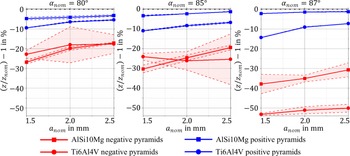
 80∘
80∘ 85∘
85∘ 87∘
87∘
 β0
β0 β1
β1 znom,+
 n
n
 σmax
σmax 70∘/75∘/80∘/85∘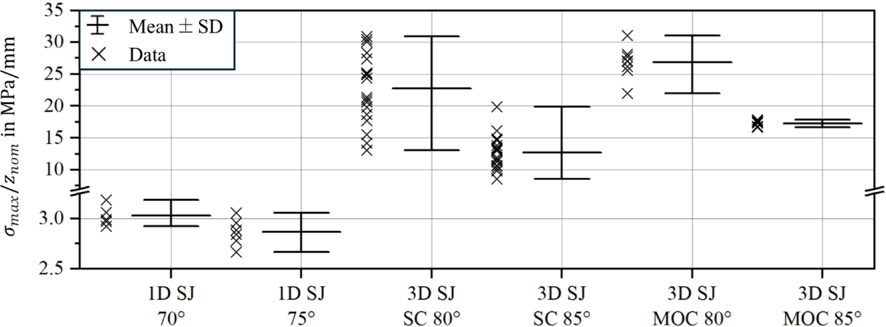
 σmax/znom
 Open access

