


1. INTRODUCTION
For Global Navigation Satellite Systems (GNSS), it is well known that modulation design has a significant effect on accuracy. The first generation GNSS signals employ Phase Shift Keying (PSK) modulation with conventional rectangular (non-return to zero) spreading symbols (referred to here as PSK-R). To deal with the restrictions brought by PSK-R, such as signal vulnerability, bandwidth limitations and the difficulties of further development of accuracy, Binary Offset Carrier (BOC) modulation was adopted (Betz, Reference Betz2002). BOC modulation can provide spectral isolation from heritage signals modulated in the same carrier frequency as well as offering performance advantages. Though BOC modulation can be seen as a more advanced modulation being complementary to PSK-R, there are also two problems existing in current modulations for GNSS. One is the extremely low transmission rate of navigation messages. For example, each Global Positioning System (GPS) satellite broadcasts its navigation messages at only 50 bits per second, and so 30 seconds are required to send the essential navigation data. But a clear 30 second window is not likely in a challenging environment, such as an urban canyon. Signal breaks inevitably happen or enhancement technologies are needed (Pratap and Enge, Reference Pratap and Enge2006). The other problem is that both the modulation schemes have no obvious advantages in solving signal distortion caused by multipath. Multipath effects could lead to unknown pseudorange errors, which can dominate other sources of error. As a result, it may be necessary to design a new GNSS signal system to obtain better performance.
In this paper, Orthogonal Frequency Division Multiplexing (OFDM) modulation is proposed to be used in the design of new GNSS signal systems. OFDM has been studied intensively over many years. It is a parallel transmission technique that transmits a large block of data symbols in parallel using numerous orthogonal subcarriers. As a broadband transmission scheme, high transmission rate can be achieved and the transmission quality is also ensured. Furthermore, OFDM is attractive as it has the benefit of separating the transmission into multiple narrowband subchannels that brings great robustness against unwanted multipath propagation effects. OFDM is highly spectrally efficient and allows for a low-complexity receiver implementation (Cho et al., Reference Cho, Kim, Yang and Kang2010). OFDM used as a modulation scheme in GNSS has been investigated over the past few years (Dai et al., Reference Dai, Wang, Wang and Yang2010; Del Peral-Rosado et al., Reference Del Peral-Rosado, Lopez-Salcedo, Seco-Granados, Zanier and Crisci2012; Diez et al., Reference Diez, de Castro, Palomo and Tossaint2010; Emmanuele and Luise, Reference Emmanuele and Luise2010; Gentner et al., Reference Gentner, Sand and Dammann2012; Mensing and Dammann, Reference Mensing and Dammann2008; Paonni et al., Reference Paonni, Mateu, Issler, Eissfeller, Ries, Boulanger, Mulassano, Caporale, Germaine, Guyomard, Bastide, Godet, Hayes, Serant, Thevenon, Julien, Pratt, Rodriguez, Wallner and Hein2010; Shahmansoori et al., Reference Shahmansoori, Montalban, Lopez-Salcedo and Seco-Granados2014; Zanier and Luise, Reference Zanier and Luise2008). However, to the best of our knowledge, research so far has been mainly concentrated in the use of an OFDM signal (or other multicarrier signal) as a ranging signal. From our perspective, the principal advantages of OFDM modulation are the high data rate, excellent anti-multipath performance and low computational complexity, not the ranging capability. Whatever Time Of Arrival (TOA) estimation methods with OFDM signal are in use, the performance is synthetically lower than that of the current ranging code modulated by PSK-R or BOC according to the present literatures. So considering an OFDM signal as a potential ranging signal for future generations of GNSS is not a good choice. Taking full advantage of OFDM modulation and considering the quality of the current modulation schemes, a novel GNSS signal system is proposed in this paper. In the new signal system, navigation messages are modulated by OFDM for high transmission rate and conventional ranging codes are still transmitted by PSK-R or BOC modulation for precise ranging. Both the signal components complement each other: Due to OFDM signals and PSK-R or BOC signals sharing the same frequency spectrum, the channel estimation results carried out by the OFDM component can be used in the processing procedure of ranging code to improve the anti-multipath performance. Using the estimated values of Doppler frequency shift and signal propagation delay coming from the PSK-R or BOC component, OFDM could obtain timing and frequency synchronisation without any synchronisation overhead, such as the insertion of pilot symbol or processing delay. Simulation results show that using the proposed GNSS signal system, stable and high transmission quality as well as high transmission efficiency for navigation data can be achieved. Also, anti-multipath performance is significantly improved compared with the current GNSS signal system.
The remainder of this paper is organised as follows. In Section 2, the basic principle of OFDM modulation is presented. Section 3 describes the proposed signal system and the approach for receiver signal processing is investigated. In Section 4, simulations are carried out to confirm the validity of the proposed signal system. Finally, conclusions are made in Section 5.
2. OFDM MODULATION
OFDM is a block modulation scheme. Figure 1 shows the typical block diagram of a baseband OFDM modulator. The serial data bits are first modulated resulting in the symbol vector S k = [S k [0], S k [1], …, S k [M − 1]], where the subscript k is the index of an OFDM symbol (spanning the M subcarriers). Note that in principle it is possible to use different modulations (e.g. Binary Phase Shift Keying (BPSK) or Quadrature Phase Shift Keying (QPSK)) on each subcarrier. After Serial to Parallel (S/P) conversion, the vector of data symbols S k then passes through an Inverse Fast Fourier Transform (IFFT) resulting in a set of N complex time domain samples [s k [0], s k [1], …, s k [N − 1]] T . In a practical OFDM system, the number of processed subcarriers is greater than the number of modulated subcarriers (i.e. N ≥ M), with the unmodulated subcarriers being padded with zeros (Sesia et al., Reference Sesia, Toufik and Baker2009. P.117). The output of the IFFT is then Parallel-to-Serial (P/S) converted and forms an OFDM symbol x k (x k = [x k [0], x k [1], …, x k [N − 1]]).
OFDM modulation by means of IFFT processing.

The above-described process can be expressed as (Dahlman et al., Reference Dahlman, Parkvall, Sköld and Beming2007)
 $$\eqalign{x_k [n] &= x_k [nT_s ] = \sum\limits_{m = 0}^{M - 1} {x_k^m [nT_s ] = \sum\limits_{m = 0}^{M - 1} {S_k [m]e^{\,j2\pi m\Delta fnT_s}}} \cr &= \sum\limits_{m = 0}^{M - 1} {S_k [m]e^{\,j2\pi mn/N} = \sum\limits_{m = 0}^{N - 1} {S^{\prime}_k [m]e^{\,j2\pi mn/N} = {\rm IDFT}[S^{\prime}_k [m]]}}} $$
where
 $$S^{\prime}_k [m] = \left\{ {\matrix{ {S_k [m],} & {0 \le m \lt M} \cr {0,} & {M \le m \lt n} \cr}} \right.$$
T s is the sampling time, the reciprocal of sampling frequency f s ; Δf is the subcarrier spacing. The relationship between f s and Δf can be described as
 $$f_s = N \cdot \Delta f = 1/T_s $$
The next key operation in the generation of an OFDM signal is the creation of a guard period at the beginning of each OFDM symbol, to eliminate the remaining impact of inter-symbol interference caused by multipath propagation. The guard period is obtained by adding a Cyclic Prefix (CP) at the beginning of the symbol x k (Van Nee and Prasad, Reference Van Nee and Prasad2000). The CP is generated by duplicating the last G samples of x k and appending them at the beginning. After CP insertion, the OFDM modulation is completed.
In the time domain, a basic OFDM signal x
k
[n] during the time interval kT
u
≤ nT
s
< (k + 1)T
u
can be indicated as Equation (1). In this equation, $x_k^m [nT_s ]$
is the mth modulated subcarrier with frequency f
m
= m · Δf and S
k
[m] is the modulation symbol applied to the mth subcarrier during the kth OFDM symbol interval. OFDM transmission is thus block-based, implying that, during each OFDM symbol interval, M modulation symbols are transmitted in parallel, which is the reason for the high data transmission efficiency of OFDM modulation.
$x_k^m [nT_s ]$
is the mth modulated subcarrier with frequency f
m
= m · Δf and S
k
[m] is the modulation symbol applied to the mth subcarrier during the kth OFDM symbol interval. OFDM transmission is thus block-based, implying that, during each OFDM symbol interval, M modulation symbols are transmitted in parallel, which is the reason for the high data transmission efficiency of OFDM modulation.
In the frequency domain, OFDM converts the available transmission bandwidth into a parallel collection of orthogonal, overlapping, narrow band subcarriers, and per-subcarrier spectrum is sinc-shaped (sinc(x) = sin (x)/x), as illustrated in Figure 2. To avoid carrier leakage, all the centre frequencies of subcarriers are distributed at the two sides of the carrier frequency. Due to the narrow bandwidth of each subcarrier (the main lobe of each sinc function), OFDM modulation has a good capacity to resist multipath effect. The reason is that in the narrow spectrum range of the main lobe corresponding to each subcarrier, the channel can be considered as flat, although the channel distortion caused by multipath exists from the whole transmission bandwidth point of view.
The spectrum of baseband OFDM signal, where M = 12, N = 16, Δf = 1 Hz, T u = 1s, and the average power of each subcarrier is unit.

To maintain the orthogonality of any two subcarriers with a minimum frequency separation, which means a high spectral efficiency, the subcarrier spacing should be equal to the per-subcarrier modulation rate 1/T
u
, where T
u
is the duration of one OFDM symbol and T
u
= NT
s
. When the condition is satisfied, all the interferences from other subcarriers to the peak point of one subcarrier (the frequency domain sampling point regarding to OFDM demodulation) are zeros, as can be seen in Figure 2. Furthermore, the orthogonality of two OFDM subcarriers $x_k^{m_1} [nT_s ]$
and
$x_k^{m_1} [nT_s ]$
and $x_k^{m_2} [nT_s ]$
over the time interval kT
u
≤ nT
s
< (k + 1)T
u
can be also interpreted as (Dahlman et al., Reference Dahlman, Parkvall, Sköld and Beming2007)
$x_k^{m_2} [nT_s ]$
over the time interval kT
u
≤ nT
s
< (k + 1)T
u
can be also interpreted as (Dahlman et al., Reference Dahlman, Parkvall, Sköld and Beming2007)
 $$\eqalign{& \int\limits_{kN}^{(k + 1)N} {x_k^{{m_1}} [n{T_s}]} x_k^{m_2^{\ast} } [n{T_s}]dn = \,\,\int\limits_{kN}^{(k + 1)N} {{{S_k^{\prime}}}[{m_1}]{{S_k^{\prime}}^{\ast}} [{m_2}]} \cr &\quad\times {e^{\,j2\pi {m_1}\Delta fn{T_s}}}{e^{ - j2\pi {m_2}\Delta fn{T_s}}}dn = 0\quad {\rm for}\quad {m_1} \ne {m_2}}$$
3. RECEIVER PROCESSING OF THE PROPOSED SIGNAL SYSTEM
3.1. The Proposed GNSS Signal System
Prompted by the idea that data-free signal components are very useful in low Signal-to-Noise Ratio (SNR) environments arising from the modernised GPS signals (Holmes and Raghavan, Reference Holmes and Raghavan2004), in the proposed signal system, the navigation data and Pseudo Random Noise (PRN) code(s) (ranging code) are transmitted by respective modulation schemes. The PSK-R or BOC modulation is chosen for the transmission of PRN code(s) which is not modulated with data, and the navigation data is modulated by OFDM modulation. The proposed GNSS signal can be expressed as
 $$\eqalign{s(t) &= \sqrt {\displaystyle{{P_D} \over M}} \sum\limits_{k = - \infty} ^\infty {\sum\limits_{n = - N/2}^{N/2} {D^{\prime}_k (n)f\,(t - kT_u} )\exp [\,j2\pi (\,f_0 + n\Delta f)(t - kT_u )]} \cr & \quad + \sqrt {2P_{PRN}} \cos [2\pi f_0 t + \varphi (C(t))] \cr D^{\prime}_k (n) &= \left\{ {\matrix{ {D_k (n)} & { - M/2 \le n \le M/2} \cr 0 & { - N/2 \le n \lt - M/2\;or\;M/2 \lt n \le N/2} \cr}} \right. \cr D_k (n) &= \exp [\,j\varphi (d_k^n (m))]\quad 0 \le m \le {\it l} \cr f\,(t) &= \left\{ {\matrix{ 1 & {0 \le t \lt T_u} \cr 0 & {{\rm otherwise}} \cr}} \right.} $$
where P
D
and P
PRN
denote the average power of the first and second term of s(t) respectively; f
0 is the nominal frequency of carrier; Δf is the subcarrier spacing; T
u
is the OFDM symbol interval; k is the index of OFDM symbol; n is the index of subcarrier; N is the total number of subcarriers; M is the number of data symbols transmitted in parallel by one OFDM symbol; C(t) denotes the PRN code(s) signal and $d_k^n (m)$
denotes the navigation data bits which will be mapped as a symbol transmitted through the nth subcarrier of the kth OFDM symbol;
$d_k^n (m)$
denotes the navigation data bits which will be mapped as a symbol transmitted through the nth subcarrier of the kth OFDM symbol; $\varphi ( \bullet )$
indicates constellation modulation, such as BPSK, QPSK etc; I is the modulation level. For example, l = 1 when the BPSK modulation is adopted and l = 2 when the QPSK modulation is adopted.
$\varphi ( \bullet )$
indicates constellation modulation, such as BPSK, QPSK etc; I is the modulation level. For example, l = 1 when the BPSK modulation is adopted and l = 2 when the QPSK modulation is adopted.
As shown in Equation (4), there are two signal components sent by one satellite. The first is the PSK-R or BOC signal which carries the PRN code(s) for precise ranging. The second is the OFDM signal that takes along the navigation data plus pilots for high information transmission rate and channel estimation. In this paper, we call them the PRN code(s) signal component and the navigation data signal component respectively. The two signal components share the same spectrum, as shown in Figure 3.
The spectrum of the proposed GNSS signal system: (a) Amplitude spectrum; (b) Power spectrum.

Figure 3 is a schematic diagram of the spectral relationship between the two signal components through simulation, where the heavy lines indicate the spectrum of the PRN code(s) signal component. All the simulations are on the assumption that the OFDM navigation data symbols S k and the binary PRN code(s) have the normalised amplitude, and the carrier is ignored for simplicity because the influences of carrier on the spectrum characteristics of the two signal components are equal. It can be seen clearly from Figure 3 that the amplitude and power per unit band of navigation data signal modulated by OFDM are much larger than that of the PRN code(s) signal modulated by the PSK-R or BOC modulation. This claim is further proved quantifiably by the following formulae.
The spectrum of the PRN code(s) signal component (ignoring the carrier) can be described as
 $$S_{PRN} (\,f) = \sqrt {2P_{PRN}} T_c \sin (\pi fT_c )\sum\limits_{n = 0}^{N_c - 1} {c_n \exp ( - j2\pi fnT_c )} $$
where T c is the chip duration of the PRN code(s); N c is the total number of chips in one period of the PRN code(s); c n is the nth element of the PRN sequence and the quantity of which is +1 or − 1.
The spectrum of the navigation data signal component (ignoring the carrier) can be described as
 $$S_D (\,f) = \sqrt {\displaystyle{{P_D} \over M}} T_u \sum\limits_{n = - N/2}^{N/2} {{\rm sinc(}\pi {\rm (}f - n\Delta f\,{\rm )}T_u )} $$
Due to the two signal components sharing the same spectrum, that is the spectrum range of the navigation data signal component corresponding to the spectral main-lobe of the PRN code(s) signal component, the relationship between the relevant parameters can be expressed as
 $$M \cdot \Delta f = M \cdot \displaystyle{1 \over {T_u}} \le \displaystyle{1 \over {2T_c}} $$
In order to evaluate the level of the mutual interference caused by the two signal components, some comparisons are made, including the amplitude spectrum and power spectral density of each signal component, as shown in Table 1.

From Table 1, we can further deduce
 $$R_A = \displaystyle{{S_{A - D} (\,f)_{\max}} \over {S_{A - PRN} (\,f)_{\max}}} = \sqrt {\displaystyle{{P_D} \over {2MP_{PRN}}}} \displaystyle{{T_u} \over {T_c}} $$
 $$R_P = \displaystyle{{S_{P - D} (\,f)_{\max}} \over {S_{P - PRN} (\,f)_{\max}}} = \displaystyle{{P_D T_u} \over {2MP_{PRN} T_c}} $$
We take the GPS C/A code(s) for example. Assuming that the average power of PRN code(s) signal component P
PRN
is 6dB lower than the average power of one OFDM subcarrier $\displaystyle{{P_D} \over M}$
belonging to the navigation data signal component, T
u
= 0·1 ms, T
c
= 1 μs and M = 180, R
A
and R
P
can be calculated, and the results are 141 (43dB) and 200 (23dB) respectively.
$\displaystyle{{P_D} \over M}$
belonging to the navigation data signal component, T
u
= 0·1 ms, T
c
= 1 μs and M = 180, R
A
and R
P
can be calculated, and the results are 141 (43dB) and 200 (23dB) respectively.
So for the navigation data signal component, the PRN code(s) signal component can be seen as noise, the existence of which does not significantly affect the demodulation of the OFDM navigation data signal.
Conversely, in the process of pseudorange measurement using PRN code(s) signal, the despreading operation referring to the received satellite signal is needed. The result of despreading is that the PRN code(s) signal becomes a narrow-band signal whose bandwidth is determined by the coherent integration time while each OFDM subcarrier signal becomes a wide-band signal whose bandwidth depends on the chip duration of the PRN code(s). After despreading, the spectrum of the PRN code(s) signal component can be expressed as
 $$S_{PRN - ds} (\,f) = \sqrt {2P_{PRN}} T_{co} {\rm sinc}(\pi fT_{co} )$$
where T co is the coherent integration time.
While the spectrum of the navigation data signal component becomes
 $$S_{D - ds} (\,f) = \sqrt {\displaystyle{{P_D} \over M}} T_c \sum\limits_{n = - N/2}^{N/2} {{\rm sinc(}\pi {\rm (}f - n\Delta f\,{\rm )}T_c )} $$
Then the influence of the navigation data signal component on the pseudo-range measurement can be evaluated by Equations (12) and (13).
 $${R_{A - ds}} \approx \displaystyle{{\sqrt {2P_{PRN}}} \over {M\sqrt {\displaystyle{{P_D} \over M}}}} \displaystyle{{T_{co}} \over {T_c}} = \displaystyle{1 \over M}\sqrt {\displaystyle{{2MP_{PRN}} \over {P_D}}} \displaystyle{{T_{co}} \over {T_c}} $$
 $${R_{P - ds}} \approx \displaystyle{{2P_{PRN}} \over {M\displaystyle{{P_D} \over M}}}\displaystyle{{T_{co}} \over {T_c}} = \displaystyle{{2P_{PRN} T_{co}} \over {P_D T_c}} $$
where R A−ds denotes the ratio of the peak value of the amplitude spectrum corresponding to the PRN code(s) signal component to the one corresponding to the navigation data signal component after despreading; R P−ds denotes the ratio of the peak value of the power spectral density corresponding to the PRN code(s) signal component to the one corresponding to the navigation data signal component after despreading.
If we let T co equal to 0·5 s, and the values of other parameters are the same as above, the calculated results of R A−ds and R P−ds are 1964 (66 dB) and 1389 (31 dB) respectively. So the negative effect of the navigation data signal component on the PRN code(s) signal component is negligible.
Based on the above analysis, the design that lets two signal components share the same spectrum is feasible.
The procedure of signal generation is illustrated in Figure 4. In this figure, the navigation data and PRN code(s) pass through different modulation paths, and are superimposed together at the end. The insertion of pilot symbols in OFDM modulation is aimed at channel estimation. The pilot pattern can be designed according to the time and frequency characteristics of the channel. Before superposition, power control is needed for each branch so as to reduce their mutual interference.
Generation procedure of the proposed GNSS signal system.

Although an additional modulation path means a raise of complexity compared with the current GNSS transmission equipment, it is not becoming the bottleneck for practicality. On the one hand, a principal advantage of OFDM modulation is that OFDM requires much lower computational complexity for high-data-rate transmission, and the complexity for each OFDM symbol is of the order O(Nlog2 N) (Andrews et al., Reference Andrews, Ghosh and Muhamed2007. P.143) where N is the total number of subcarriers. On the other hand, considering the development of Digital Signal Processing (DSP) technology and the large scale integrated circuit as well as the OFDM itself being a mature technology, the effects of incremental complexity on the realisation of transmission equipment and its costs are acceptable.
3.2. Receiver Signal Processing
The receiver signal processing procedure relating to the proposed GNSS signal system is described in this section. Figure 5 shows a complete block diagram of a typical receiver. After signal conditioning and frequency conversion through the radio frequency (RF) front end, the resulting digital medium frequency satellite signal is delivered into two branches. One is the OFDM demodulation link for recovering navigation data and the other is the GNSS receiver baseband processing procedure for PSK-R or BOC signal demodulation with several observations being achieved, such as Doppler frequency shift and signal propagation delay etc. With the observations and navigation messages, the estimated values of position, velocity and time can be calculated by the navigation processing module. Furthermore, the backward compatibility with current GNSS signal system and its receiving technology are also considered in the design of the proposed GNSS signal system. With an addition of a low-complexity OFDM demodulation link and small changes of the present baseband link, the receiver can process the proposed satellite navigation signal as well as older signals.
The block diagram of a typical receiver responding to the proposed GNSS signal system.

The proposed GNSS signal system brings some changes in the processing procedure of conventional OFDM and PSK-R or BOC demodulation that can provide advantages in implementation and performance. Based on the measurements of Doppler frequency shift and signal propagation delay from the PSK-R or BOC demodulation branch, the procedure of timing and frequency synchronisation in the OFDM link can be greatly simplified. Besides, the channel estimation results from the OFDM demodulation branch can be used in the acquisition and tracking stage of PSK-R or BOC demodulation to further improve the anti-multipath performance in harsh environments.
The structure of the OFDM assisted acquisition module and code tracking loop are illustrated in Figures 6 and 7 respectively. Compared with traditional processing procedures, the channel equalisers are added both in signal acquisition and code tracking stages. The equalisation takes effect to compensate for the signal corruption caused by multipath as well as to reject the noise/interference. Considering a trade-off between computation complexity and performance, frequency domain Minimum Mean Square Error (MMSE) equalisation is considered. The digital Intermediate Frequency (IF) satellite signal is first multiplied with local generated carrier signal and its 90°phase-shifted signal. The results are named I-branch signal and Q-branch signal respectively, which can be expressed together as a form of complex, i.e. I + jQ. Then the complex signal which is assumed to have N samples is transformed into the frequency domain by means of a size-N Discrete Fourier Transform (DFT). The equalisation is then carried out as frequency domain filtering, with the frequency domain filter taps W 0,…,W N−1. In this paper, the setting of W 0,…,W N−1 will be on the basis of MMSE norm and the detailed computational formula is shown in Equation (14) (Dahlman et al., Reference Dahlman, Parkvall, Sköld and Beming2007).
 $$W_k = \displaystyle{{H_k^{^\ast}} \over { \vert H_k \vert ^2 + P_N}} $$
The block diagram of improved acquisition algorithm with channel equalisation.

The block diagram of the proposed code tracking loop.

where P N is the noise power and H k is the sampled channel frequency response which can be obtained by the channel estimation results from the OFDM demodulation branch. Finally, for the code tracking loop, the equalised frequency domain signal is transformed back to the time domain by means of a size-N inverse DFT. For the acquisition algorithm of parallel search of the code phase, this step is not needed because the signal will be processed in the frequency domain.
Based on the proposed GNSS signal system, the effect of equalisation on resisting the multipath disturbance and improving the ranging accuracy can be interpreted by the following formulae.
First, as shown in Equation (4), the PRN code(s) (ranging code) signal component of the proposed GNSS signal can be expressed as
 $$s_{rc} (t) = \sqrt {2P_{PRN}} \cos [2\pi f_0 t + \varphi (C(t))]$$
Then transmitting to the receiver side, the corresponding signal component can be represented as
 $$r_{rc} (t) = s_{rc} (t) \otimes h(\tau, t) + n(t) = \int_0^\infty {s_{rc} (t - \tau )h(\tau, t)d\tau + n(t)} $$
where ⊗ denotes linear convolution; h(τ, t) is the time-variant channel impulse response, which describes the characteristics of the multipath fading channel; n(t) indicates the additive white Gaussian noise term. Without regard for the Doppler effect, which is not a key point for this paper, the channel impulse response can be expressed as
 $$h(\tau, t) = \sum\limits_{l = 0}^{L - 1} {a_l (t)\delta (\tau - \tau _l} (t))$$
where L is the total number of propagation paths; a l is called the delay coefficient, that is a measure of the square root of the average delay power which is assigned to the lth discrete propagation path; τ l is the discrete propagation delay corresponding to the lth discrete propagation path. In addition, all the parameters defined above are time-variant.
From Equations (16) and (17), r rc (t) can be further described as
 $$\eqalign{r_{rc} (t) = & \int_0^\infty {s_{rc} (t - \tau )h(\tau, t)d\tau + n(t)} \cr = & \int_0^\infty {s_{rc} (t - \tau )\left[ {\sum\limits_{l = 0}^{L - 1} {a_l (t)\delta (\tau - \tau _l (t))d\tau + n(t)}} \right]} \cr = & \sum\limits_{l = 0}^{L - 1} {a_l (t)s_{rc} (t - \tau _l (t)) + n(t)}} $$
Owing to ranging being based on the autocorrelation characteristic of the PRN code(s), the effect of multipath on the autocorrelation function of the PRN code(s) should be analysed. After carrier wipe off and constellation demapping, the autocorrelation result of the local PRN code(s) and the PRN code(s) wiped off from the received satellite signal (ignoring the noise) can be expressed as (according to Equations (15), (17) and (18))
 $$\eqalign{R_{CC_s} (t) & = \displaystyle{1 \over {T_{co}}} \int_0^{T_{co}} {C(t)C_{s} (t)dt} = \displaystyle{1 \over {T_{co}}} \int_0^{T_{co}} {C(t) \cdot \left[ {\sum\limits_{l = 0}^{L - 1} {a_l (t)C(t - \tau _l (t))}} \right]dt} \cr & = \sum\limits_{l = 0}^{L - 1} {a_l (t) \cdot \left[ {\displaystyle{1 \over {T_{co}}} \int_0^{T_{co}} {C(t)C(t - \tau _l (t))dt}} \right]} \cr & = \sum\limits_{l = 0}^{L - 1} {a_l (t)R(\tau _l (t))} \cr & = a_0 (t)R(\tau (t)) + \sum\limits_{l = 1}^{L - 1} {a_l (t)R(\tau _l (t))}} $$
where T
co
is the coherent integral time; C
s
(t) is the ranging code from the received satellite signal; τ is the propagation delay of the direct ray, i.e. τ = τ
l
|
l=0 and $R( \bullet )$
indicates the operation of autocorrelation.
$R( \bullet )$
indicates the operation of autocorrelation.
To simplify the discussion, we assume that the parameters (delay coefficients and discrete propagation delays) are constant over the coherent integral time we consider. In this case, $R_{CC_s} $
can be reduced to
$R_{CC_s} $
can be reduced to
 $$R_{CC_s} = a_0 R(\tau ) + \sum\limits_{l = 1}^{L - 1} {a_l R(\tau _l )} $$
From Equation (20), we can see that multipath will lead to the corruption of the autocorrelation waveform, which is so-called multipath interference, and the interference terms are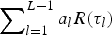 $\sum\nolimits_{l = 1}^{L - 1} {a_l R(\tau _l )} $
.
$\sum\nolimits_{l = 1}^{L - 1} {a_l R(\tau _l )} $
.
Multipath interference is illustrated in Figure 8. In this figure, a simple case of two paths is considered and the received signal consists of two components: a direct signal component and a reflected signal component. The reflected signal component is a delayed, phase-shifted, and attenuated version of the line-of-sight signal component. In case the reflected and the direct signals are in phase, the amplitude of the sum signal is larger than the amplitude of each of the components and the autocorrelation peak of the reflected signal will be added to the autocorrelation peak of the direct signal. This is called constructive interference where the pseudorange is measured long, as shown in Figure 8 (a). On the other hand, if the reflected and the direct signals are out of phase, the amplitude of the sum signal decreases and the autocorrelation peak of the reflected signal is subtracted from the autocorrelation peak of the direct signal. This is called destructive interference where the measured pseudorange is short, as shown in Figure 8 (b). In general, the phase of the reflected signal component varies and assumes all possible angles relative to the direct ray. Hence, the actual shape of autocorrelation curve continuously varies and depends on the angle and magnitude of the reflected signal component relative to the direct signal component, and the multipath error swings between upper (constructive interference) and lower (destructive interference) bounds.
Constructive and destructive multipath interference.

The BER performance of navigation data demodulation in different scenarios.

Historically, to handle the corruption caused by multipath and restore the original autocorrelation shape, equalisation is the main method that can be considered and applied at the receiver side. The principle of equalisation is using the channel characteristics to compensate for the signal corruption caused by transmitting in the non-ideal channel environment, such as multipath. The procedure of equalisation can be expressed as
 $$r_{eq} (t) = r_{rc} (t) \otimes w(\tau ) = [s_{rc} (t) \otimes h(\tau ) + n(t)] \otimes w(\tau )$$
where w(τ) is the impulse response of an equaliser. To reduce the complexity, the equalisation can be carried out in the frequency domain. According to the properties of Discrete Fourier Transform, the procedure of frequency domain equalisation can be expressed as
 $$R_{eq} (k) = R_{rc} (k) \cdot W_k = [S_{rc} (k) \cdot H_k + P_{Nk} ] \cdot W_k, \quad k = 0,1, \cdots, N - 1$$
where R eq (k) is the Discrete Fourier Transform of digitised r eq (t); R rc (k) is the Discrete Fourier Transform of digitised r rc (t); S rc (k) is the Discrete Fourier Transform of digitised s rc (t); P Nk is the sampled noise power. The frequency domain equaliser tap W k which is the Discrete Fourier Transform of digitised w(τ) is set based on MMSE criterions and the corresponding formula is according to Equation (14). Then the equalised signal can be further expressed as
 $$\eqalign{R_{eq} (k) &= R_{rc} (k) \cdot W_k = [S_{rc} (k) \cdot H_k + P_{Nk} ] \cdot \displaystyle{{H_k^{^\ast}} \over { \vert H_k \vert ^2 + P_N}} \cr &= S_{rc} (k)\displaystyle{{ \vert H_k \vert ^2} \over { \vert H_k \vert ^2 + P_N}} + P_{Nk} \cdot \displaystyle{{H_k^{^\ast}} \over { \vert H_k \vert ^2 + P_N}}, k = 0,1, \ldots, N - 1} $$
From Equation (23) it can be seen that equalisation provides full compensation for any non-ideal channel characteristics and thus full suppression of any related signal corruption, where $\displaystyle{{\vert{H_k} \vert}^2} \over {{\vert{H_k} \vert}^2} + {P_N} $
is only a real-valued constant quantity which cannot lead to any distortion of S
rc
(k), and the noise term
$\displaystyle{{\vert{H_k} \vert}^2} \over {{\vert{H_k} \vert}^2} + {P_N} $
is only a real-valued constant quantity which cannot lead to any distortion of S
rc
(k), and the noise term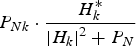 ${{P_{Nk}} \cdot {\displaystyle {H_k^{\ast}} \over {\vert{H_k} \vert}^2 + {P_N}}}$
ensures a low noise level even in the case of the quantity of |H
k
| being extremely small.
${{P_{Nk}} \cdot {\displaystyle {H_k^{\ast}} \over {\vert{H_k} \vert}^2 + {P_N}}}$
ensures a low noise level even in the case of the quantity of |H
k
| being extremely small.
Using frequency domain equalisation, an important prerequisite is that the sampled channel frequency response H k should be known. Considering the present GNSS signal system and the corresponding receiving technology, the channel estimation and equalisation algorithm is little adopted because of the high calculation complexity. However, using the proposed signal system, frequency domain channel estimation is easily realised by means of pilots belonging to the OFDM signal component and all the estimated values of H k (k = 0, 1, …, N − 1) can be obtained through interpolation. Due to the two signal components from one satellite sharing the same spectrum and transmitting through the same channel, the estimated results of H k (k = 0, 1, …, N − 1) from the OFDM demodulation branch can also be used in the frequency domain equalisation procedure of the PSK-R or BOC demodulation branch. Thus the multipath interference as well as noise and other interferences could be effectively suppressed, and the ranging precision will be improved accordingly.
There are two main challenges in the processing procedure of the proposed GNSS signal. The first is that for one signal component, the other component is interference. It is not a serious problem for PSK-R or BOC demodulation branches because of the spread spectrum gain and the benefits of no data being modulated in this component, which is explicit in Section 3.1. However, for the OFDM demodulation branch, some technology can be used to further increase the signal quality, such as channel coding and Multi-Input Multi-Output (MIMO). The second question is the Multi-Access Interference (MAI) between the OFDM signal components from different satellites. It can be solved by fixed beam antenna array technology, i.e. Space Division Multiple Access (SDMA), which can also improve the Signal to Interference Ratio (SIR) of each demodulation link. Due to the navigation information recovered from different satellites being the same, the diversity reception can be achieved and a better transmission quality can be obtained.
4. PERFORMANCE ANALYSIS AND SIMULATIONS
In this section, a series of simulations are made to evaluate the performance of the proposed GNSS signal system. The simulation conditions are shown in Table 2.
Simulation conditions.

Based on the proposed GNSS signal system and the simulation conditions, first, the transmission quality of the navigation data is evaluated through BER (Bit Error Rate) performance. Although the BER performance is not directly related to navigation precision, it reflects the accuracy of the navigation data bits recovered at the receiver. Due to the accuracy of the navigation message being one of the major factors that influence navigation precision, the BER is undoubtedly an important metric that needs to be paid attention to. In the simulation, three scenarios are considered. The results are shown in Figure 9.
From the three simulation curves, we can see that the BER performances of navigation data demodulation in three scenarios are not largely different, which means stable performance can be achieved using the proposed GNSS signal system. In the three scenarios, the performance corresponding to a typical urban area is slightly better than the other two. Even in the worst scenario, i.e. bad urban, the requirements of BER performance for high navigation precision still can be satisfied. It can be seen that when SNR reaches 10 dB, the BER drops down to about 10−4.
Second, the transmission efficiency of navigation data can be estimated by Equation (24).
 $$\eqalign{& R_b = \displaystyle{{(M - N_p ) \cdot l \cdot r_c} \over {T_u + T_{CP}}} = \displaystyle{{(M - N_p ) \cdot l \cdot r_c} \over {T_s (N + G)}} = \displaystyle{{(M - N_p ) \cdot l \cdot r_c} \over {\displaystyle{1 \over {N \cdot \Delta f}}(N + G)}} \cr &\quad = \displaystyle{{(180 - 30) \times 1 \times \displaystyle{1 \over 2}} \over {\displaystyle{1 \over {256 \times 10000}}(256 + 20)}} = 695652\;(bits/s)} $$
where R b denotes the transmission rate of navigation data; N p is the number of pilots transmitted by one OFDM symbol; r c is the code rate for channel coding; the means of the other parameters are the same as sections above (such as Section 3.1.).
With the assumptions listed in Table 2, the transmission rate of navigation data is calculated by Equation (24). The result is much larger than the 50 bits/s data rate of GPS. So the time spent on transmitting all the navigation bits must be much shorter than current GNSS.
Third, the anti-multipath performance is examined compared with current GNSS signal systems. The rural area scenario is chosen to evaluate the effect of multipath on signal acquisition. Figure 10 shows the resulting detection probability curves corresponding to the two different signal systems respectively.
The simulation result of detection probability (rural area scenario).

From Figure 10, we can see that the proposed signal system has a substantially better performance in a multipath environment. Under the condition of low SNR, the advantage of the proposed signal system is obvious. With the increase of SNR, both the signal systems tend to have the same performance.
To examine the effect of multipath on the code tracking for different signal systems, the comparison of pseudorange errors corresponding to Coarse/Acquisition (C/A) code using the proposed signal system and the current GPS C/A code is carried out and shown in Figures 11 to 13 with different Delay Lock Loop (DLL) correlator spacings. In these series of simulations, a simple two-path multipath model as a specular reflection is considered, with the reflected path 6 dB weaker than the direct path and all values time-invariant over the time period of interest. Besides, the simplest coherent discriminator is chosen and the pre-correlation bandwidth is assumed infinite. Then, the output of the envelope discriminator can be represented as
 $$\varepsilon (t) = \vert I_E (t) \vert - \vert I_L (t) \vert $$
Pseudorange errors caused by −6 dB specular multipath for C/A code using the proposed signal system and the current GPS C/A code (d = 1 chip).

Pseudorange errors caused by −6 dB specular multipath for C/A code using the proposed signal system and the current GPS C/A code (d = 0·5 chip).

Pseudorange errors caused by −6 dB specular multipath for C/A code using the proposed signal system and the current GPS C/A code (d = 0·1 chip).

where I E (t) and I L (t) denote the correlation outputs corresponding to the early replica and the late replica respectively.
Further assume that the process of carrier wipe off is complete and the frequency difference between the satellite signal and the locally generated carrier signal is ignored, then I E (t) and I L (t) can be expressed as (Borre et al., Reference Borre, Akos, Bertelsen, Rinder and Jensen2006)
 $$\eqalign{I_E (t) &= A_1 R_C (\tau _1 - \hat \tau - \delta )D(t - \tau _1 ) + A_2 R_C (\tau _2 - \hat \tau - \delta )\exp (\,j\psi (t))D(t - \tau _2 ) \cr& \approx \left[ {A_1 R_C (\tau _1 - \hat \tau - \delta ) + A_2 R_C (\tau _2 - \hat \tau - \delta )\exp (\,j\psi (t))} \right]D(t - \tau _1 ) \cr I_L (t) &= A_1 R_C (\tau _1 - \hat \tau + \delta )D(t - \tau _1 ) + A_2 R_C (\tau _2 - \hat \tau + \delta )\exp (\,j\psi (t))D(t - \tau _2 ) \cr& \approx \left[ {A_1 R_C (\tau _1 - \hat \tau + \delta ) + A_2 R_C (\tau _2 - \hat \tau + \delta )\exp (\,j\psi (t))} \right]D(t - \tau _1 )} $$
where A
1 and A
2 denote the amplitude of the direct path and the reflected path component respectively; τ
1 and τ
2 denote the propagation delay of the direct path and the reflected path component respectively; $\hat \tau $
denotes the estimated delay; δ denotes the spacing between the early replica (or the late replica) and the prompt code; D denotes the navigation message;
$\hat \tau $
denotes the estimated delay; δ denotes the spacing between the early replica (or the late replica) and the prompt code; D denotes the navigation message; $R_C ( \bullet )$
denotes the correlation function of the C/A code; ψ(t) denotes the instantaneous phase difference between the two signal components.
$R_C ( \bullet )$
denotes the correlation function of the C/A code; ψ(t) denotes the instantaneous phase difference between the two signal components.
According to Equation (26), the envelope discriminator output can be further expressed as
 $$\eqalign{\varepsilon (t) & = \vert A_1 R_C (\tau _1 - \hat \tau - \delta ) + A_2 R_C (\tau _2 - \hat \tau - \delta )\exp (\,j\psi (t)) \vert \cr &\quad - \vert A_1 R_C (\tau _1 - \hat \tau + \delta ) + A_2 R_C (\tau _2 - \hat \tau + \delta )\exp (\,j\psi (t)) \vert} $$
where the relative phase ψ(t) generally changes over time. Therefore, the envelope of the received signal will fluctuate over time as the two signal components interfere.
In Equation (27), the terms of $A_2 R_C (\tau _2 - \hat \tau - \delta )\exp (j\psi (t))$
and
$A_2 R_C (\tau _2 - \hat \tau - \delta )\exp (j\psi (t))$
and $A_2 R_C (\tau _2 - \hat \tau + \delta )\exp (j\psi (t))$
are the cause of pseudorange error. The upper and lower boundaries of pseudorange error are corresponding to the cases of exp (jψ(t)) = 1 and exp (jψ(t)) = −1 respectively.
$A_2 R_C (\tau _2 - \hat \tau + \delta )\exp (j\psi (t))$
are the cause of pseudorange error. The upper and lower boundaries of pseudorange error are corresponding to the cases of exp (jψ(t)) = 1 and exp (jψ(t)) = −1 respectively.
As can be seen from Figures 11 to 13, using the proposed signal system could provide significantly smaller multipath-induced pseudorange error over the range of multipath delays. When the value of DLL correlator spacing is set to 1·0, the proposed signal system has a worst-case pseudorange error of 7·85 m, compared with 74·95 m for current GPS C/A code signal. When the value of DLL correlator spacing is set to 0·5, the proposed signal system reduces the worst-case pseudorange error from 37·5 m to 6·89 m. When the value of DLL correlator spacing is set to 0·1, the worst-case pseudorange error is 7·5 m for current GPS C/A code signal while 0·8526 m for the proposed signal system. Based on these values, it is clear that the tracking accuracy can be improved through decreasing DLL correlator spacing. However, decreasing DLL correlator spacing means greatly increasing complexity. The proposed signal system with a DLL correlator spacing of 1·0 could reach the performance of current GPS C/A code signal with a DLL correlator spacing of 0·1, which may imply less receiver complexity.
5. CONCLUSIONS
In this paper, OFDM modulation is proposed to be used in the design of a new GNSS signal system to solve two main problems for current modulations, namely extremely low transmission rate of navigation message and pseudorange error caused by multipath. In the new signal system, navigation messages are modulated by OFDM for high transmission rate and conventional ranging code is transmitted still by PSK-R or BOC modulation for precise ranging, and the two signal components share the same spectrum. Corresponding to the proposed GNSS signal system, the receiver signal processing procedure is also discussed. Through channel estimation and equalisation, the anti-multipath performance can be significantly improved. Moreover, use of OFDM modulation makes it easy to work with advanced technology, such as MIMO, which assists further performance improvements. The algorithm is worth further study. Simulation results show that by taking advantage of the proposed GNSS signal system, low BER and high data rate for navigation data as well as the excellent anti-multipath performance can be achieved. Thus the proposed new GNSS signal system can be considered to be a good choice for a future GNSS system.



