

1.1 What Is Rock Physics?
The meaning of the term assumes that “rock physics” is an application of physical methods to the study of rock properties. From the geological and mineralogical point of view, rocks may be distinguished by their macroscopic properties studied in the field and by the microscopic properties studied by mineralogists and petrologists in labs. Rocks also possess some very variable physical properties, such as density, elastic modulus, permeability, porosity, magnetic susceptibility, resistivity, etc., just like any other solid material. From the geophysical point of view, rocks are an environmental medium whose properties need to be known in order to provide an adequate interpretation of geophysical measurements. Thus, petrophysics or rock physics is a link between the branches of geoscience knowledge, such as geophysics, lithology, petrography, hydrogeology and rock mechanics.
Rock, in geology, is the general term for any naturally occurring mineral aggregate with one or more mineral phases. Rocks build up not only the Earth’s crust and mantle but also celestial bodies such as terrestrial planets, moons and asteroids. Rocks are traditionally subdivided into sedimentary rocks (sedimentites), magmatic rocks (plutonites, volcanic effusive and intrusive rocks) and metamorphic rocks after their typical formation process. Sediments are formed by deposition of weathering or erosive material of other rocks or by chemical or organic deposition processes. Magmatic rocks solidify from magmas, that is, from melts or partially molten rocks at depth or on the Earth’s surface. Metamorphic rocks form in the Earth’s crust after transformations of other types of rocks under the influence of high temperatures and pressures or in contact with fluid phases. According to the degree of mechanical consolidation, which means the way of combining and binding individual components of rocks, a distinction is also made between loose or soft rocks (e.g. sand) and hard rocks (e.g. sandstone). For example, ores are rocks in which metals have been accumulated. If they are available in economically sufficient concentrations and quantities, they are called deposits.
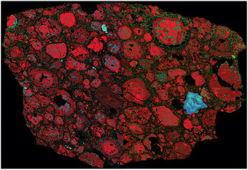
The Earth, as well as other terrestrial planets and many celestial bodies, consists of rocky shells and a core. Approximately 5 billion years ago, it was time for a rotating disk-shaped body to emerge from a cosmic molecular cloud consisting of volatile elements as well as of heavier dust particles. This may have been caused by the explosion of a nearby star (called a supernova [SN]). The explosion waves caused a squeezing of the cosmic cloud, which started to collapse. The gas and dust pulled together due to gravity and formed a solar nebula. Density and temperature inside the nebula increased, as did the spinning velocity. The energy of contraction in the center led to the ignition of nuclear fusion in the proto-Sun. Solar wind and centrifugal forces blew the light elements of hydrogen and helium away from the Sun, while the heavy ones remained close to the Sun. The innumerable individual bodies in the solar system came together in orbits and formed the inner rocky and outer gas planets over the next billion years. According to one of the plausible core accretion scenarios, the cores of protoplanets have to achieve critical masses, and only after that are the planets able to retain a gas atmosphere. This theory is a good explanation of the origin of the terrestrial planets (the four planets closest to the Sun – Mercury, Venus, Earth and Mars) but not the gas giants (Jupiter, Saturn, Uranus and Neptune). The difficulties in attributing the formation of the solar system directly to a single SN explosion are as follows (Reference Pfalzner, Davies and GounellePfalzner et al., 2015). (1) Prior to SN explosion, stars having various starting masses undergo different stages of radionuclide burning, ending in explosions in stages from hydrogen, through helium–carbon–neon–oxygen, to silicon. Each explosion burning fingerprints a specific pattern of element abundances, which differ from the solar system abundances (Reference Arnett and ClaytonArnett & Clayton, 1970). (2) The interstellar medium around a massive star prior to SN explosion is depleted of molecular clouds. It is very unlikely to find a protoplanetary disk or a dense core that close to an SN. (3) The composition of meteorites (chondrites, achondrites, and magmatic and nonmagmatic iron meteorites) indicates the past presence of short-lived radionuclides with half-lives (τ1/2) ≲ 10 Ma. The age of differentiated meteorites that experienced a heating effect from these radionuclides, largely caused by 26Al decay, triggering their differentiation into metal core and silicate mantle, is only 1–4 Ma after the formation of the solar system. The age of nondifferentiated meteorite parental bodies is only 1–2 Ma greater. (4) The abundances of the short-lived radionuclides 26Al and 60Fe and their ratio in the solar system are higher than the theoretical estimates from a silicon SN explosive bursting (Reference Arnett and ClaytonArnett & Clayton, 1970). An alternative theory, which tries to explain these contradictions, suggests that the Sun is one of a second generation of stars, whose formation was mediated by the “runaway” of a massive star due to an SN explosion. The most likely origin for 26Al is local; that is, the wind of a single massive star enriched a shell around it, and the subsequent gravitational collapse of the shell resulted in the formation of a new 26Al-rich star and other stars, including the Sun. The origin of 60Fe is due to the enhanced galactic background as a result of stars being born and dying in the same molecular cloud as the Sun but in a prior generation. The protoplanetary disk of the massive star, in which dust and gas were already bound together in clumps in the early stages of the solar system’s development, existed before the Sun’s formation. The clumps slowly compacted and formed the giant planets. Gas planets can be formed faster than terrestrial ones; it may take about 1,000 years to trap gases from the disk. The orbits of massive gas planets were rapidly stabilized, preventing them from falling down back into the Sun. A new view of the origin of the solar system and the planets suggests that solid materials or proto-rocks existed at an early stage in the form of chondrules and calcium-aluminum rich inclusions (CAIs; Figure 1.1a). CAIs were formed from molten gas droplets at high temperatures (>1,300 K), whereas chondrules were the collected dust clumps melted and rapidly cooled at lower temperatures (<1000 K). The fast spinning of material caused the disk to flatten, unevenly distributing these two sources of proto-rocks into planes along the protoplanetary disk. Local heating and remelting of cosmic proto-rocks may be caused by shock waves after material collapses onto the protoplanetary disk. Recently, it was suggested that rocks existed even at an early stage of terrestrial planet formation due to melting of chondrules and CAIs caused by spikes of electrical current in the protoplanetary disk and subsequent rapid cooling (Reference HowellHowell, 2012).
Proto-solar system rock material: combined elemental X-ray map of CR (Renazzo type) carbonaceous chondrite Northwest Africa 801. Legend: Mg (red), Ca (green) and Al (blue). The size of the largest CAI is about 400 µm. Round, almost spherical-shape fragments are chondrules, CAI are of more irregular form, and the space between chondrules and CIA is filled with matrix material.
Metallic and nonmetallic elements had differing evolution in the solar nebula. Metallic elements condensed almost as soon as the spinning disk accreted (4.55–4.56 billion years ago according to isotope measurements of certain meteorites), and the solid nonmetallic material condensed a bit later (between 4.4 and 4.55 billion years ago). As a consequence, different kinds of meteorites were formed, and their participation in the bombardment of protoplanets resulted finally in distinct shell structures of the planets.
1.2 Shell Structure of the Earth
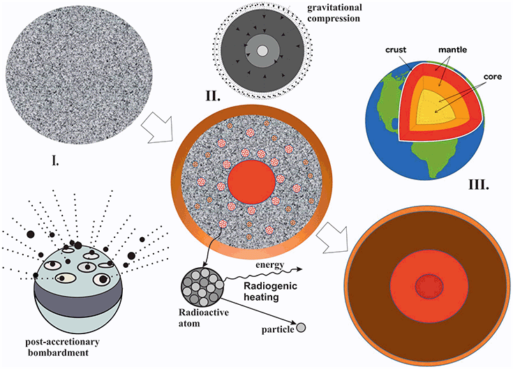
The age of the Earth is  a, based on the evidence from radiometric age-dating of meteorite materials, which is consistent with the radiometric ages of the oldest known terrestrial and lunar rock samples. Thus, at this age the first separation of substances had been completed, in which rock-forming elements such as silicon, iron, aluminum and oxygen were delivered to the overall budget. With the aggregation of planetesimals (orbital cosmic objects with a diameter of about 1 km), the first celestial bodies in the solar system were formed, and terrestrial planets like the Earth grew to their present size. The birth of the Earth was accompanied by intensive meteorite impacts for 70–80 million years. As the Earth’s melting progressed, intense magmatism and a magma ocean developed. This ensured that light silicate-rich material was transported toward the surface and heavier iron-rich material sank down. From an initially homogeneous protoplanet emerged a strictly differentiated body with a spherical shell structure (Figure 1.1b). Volatile components were transported to the outside and escaped the surface, forming an early proto-atmosphere. The solid part of the Earth differentiated further and, as in a blast furnace, a layer of slag was formed above the metal core, which mainly contained iron. This slag layer was quite powerful and massive, and included the Earth’s mantle and crust. Basically, these slag shells consisted of silicates – the Earth’s rocks.
Shell structure of the Earth. Starting as a homogeneously accreted body, the proto-Earth developed into a differentiated shell-structured planet with an iron-nickel core and a silicate-rich mantle. The uppermost part of the silicate shell, where plate tectonics is active, represents the lithosphere (“foam” of the Earth), a realm of rocks. I. Homogeneous accretion stage: Heat builds up as a planet accretes due to meteorite bombardment; II. Differentiation stage: A core is formed by Fe-Ni alloy melting, accompanied by other chemical transformations, and heat is produced due to gravitational energy release and material contraction under pressure in the center as well as by radiogenic disintegration of nonstable isotopes; III. The mantle overturn during the core formation is over: solid inner core 5,150–6,370 km, liquid core 2,891–5,150 km, silicate mantle 40–2,891 km and crust 5–40 km are built.
With the emergence of the Earth’s shell structure a further separation of matter continued, by which some specific light elements have been accumulated in the crust, the so called lithophile elements (λίθος means stone in Greek), whereas others disappeared almost completely inside the Earth’s core, the so called siderophile elements (σίδερο = iron).
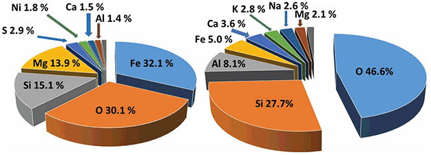
Only 8 out of about 100 natural elements account for over 99 percent of the Earth’s crust composition (Figure 1.2). All heavy elements tend to be stuck in the Earth’s interior beyond human reach and are found only in rare cases in the crust. Such elements are “noble” to us and are eagerly sought as ore deposits. This starts with iron, the Earth’s most abundant element, which forms only 6 percent of the crust by weight.
Chemical element distribution in the bulk Earth and in the crust, weight %. (a) represents the bulk Earth composition; (b) is the crust composition.
1.3 Rock Properties and Geophysical Methods
The basic concept of geophysical measurements is to categorize the structure of the Earth or other terrestrial planets and to discriminate the materials composing them. Thus, geophysical methods should be sensitive enough to reveal physical anomalies in rocks under varying temperature and pressure, and at varying degrees of fluid phase saturation. This puts a certain condition on the methods in use, which is called resolution, or the achievement of the maximum degree of structural and material detail at the lowest distance between spatially separated objects. In this case, knowledge of the physical properties of rocks is a prerequisite. The geophysical methods aiming to measure particular physical parameters are listed in Table 1.1.
| Geophysical procedure | Measured petrological parameter |
|---|---|
| |
| Propagation velocity V and absorption coefficients of elastic waves, reflection, transmission and absorption coefficients of mechanical discontinuities |
|
|
| |
| |
|
The physical background of each of the measured petrophysical parameters in the right-hand column of Table 1.1 will be presented in the following chapters of this book.
1.4 Texture and Fabric of Rocks
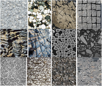
The texture of rocks is the sum of all spatial data inside a considered area; that is, the texture includes above all the information on division, sequence and spatial arrangements of constituent parts of rocks. The individual, contrasted, larger-scale features of rocks are called “structures.” The term “fabric” encompasses the terms “structure” and “texture”; it can be considered as an element of structure on a macro-scale or an element of textures on a micro-scale. Under the term “texture,” clearly one understands the spatial arrangement of crystal building blocks (ions, atoms, defects) and their reproduction in a certain geometric arrangement. In some cases the term “texture” is used for sedimentary and igneous rocks, meaning a directional feature, whereas with metamorphic rocks the term used is a “fabric.” Fabrics often mean observable characteristics of rocks, which can be studied in outcrop hand specimens and under a microscope. Thus, rock fabrics refer to the mutual relationship between grains. In contrast, rock textures refer to small-scale features in a rock, including grain size and grain shape, intergranular relations, and degree of crystallinity (amount of crystal and glass). Hard rocks are usually characterized by a holocrystalline texture, in which all the rock material is crystallized. Holocrystalline rocks are subdivided into a group having phaneritic texture, in which the minerals may be distinguished with the naked eye, and a group with aphanitic texture, in which the minerals may be discerned only under a microscope. Holocrystalline textures are subdivided according to their grain size into fine-grained (crystal size<1 mm), medium-grained (1–5 mm), coarse-grained (5–10 mm) and very coarse-grained (grain size >10 mm). Textures also depend on the shapes and habitus of constituting minerals. In some cases, minerals have ideal growth according to their crystallographic axis (habitus) and form idiomorphic crystals, while in other cases ideal mineral growth is suppressed and their shapes are distinct from an idiomorphic one; these are called allotriomorphic or xenomorphic. Minerals may be idiomorphic in relation to some sorts of minerals (their shape is closer to the ideal) and xenomorphic (their shape is more distinct from the ideal) in relation to others. The idiomorphic and allotriomorphic crystal shapes are recognized by two distinct morphologies, according to whether they grow by a diffusional mechanism from melt or from solution: (1) allotriomorphic crystals nucleate at the grain boundaries, while (2) idiomorphic crystals usually form intragranularly. Toughness and other mechanical properties of rocks are strongly affected by their microstructure. Microstructures formed by crystals nucleated at preexisting grain boundaries increase the resistance to cleavage crack propagation. If the shapes of all crystallized minerals are close to idiomorphic, the textures of hard rocks are described as panidiomorphic-granular (pyroxenites, peridotites, dunites). Textures that are represented by a combination of minerals having differing degrees of idiomorphism are called hypidiomorphic-granular (granites, syenites, diorites). Thus, rocks composed of euhedral crystals, those that are well formed with sharp, easily recognized faces, are opposite to rocks with anhedral crystal texture, that is, rocks with mineral grains having no well-formed crystal faces or cross-section shapes in thin sections. An example is the simultaneous crystallization from melt of feldspar and quartz crystals in granites, which produces pegmatitic or graphic textures with intergrowths of minerals. Depending on the size distribution of minerals, a distinction is made between equigranular and inequigranular textures (Figure 1.3).
Classification of main rock textures: a – crystalline; b – clastic-round grain, c – clastic-angular; d – cubic; e – columnar; f – parallelepiped; g – uniform; h – continuous nonuniform; i – discontinuous nonuniform; k – porphyritic; l – conglomerate; m – breccia.
Individual minerals composing rocks may or may not be bounded by their own crystal faces. Those that are bounded are termed idioblastic, while those that are not bounded are called xenoblastic. Different minerals exhibit specific tendencies to be idioblastic. A high tendency to be idioblastic is termed porphyroblastic. A distinction is made between uniformly granular (homeoblastic) and nonuniformly granular (heteroblastic) textures. A special case of heteroblastic texture is seen in the porphyroblastic texture, characterized by the presence of large mineral crystals (porphyroblasts) within a fine-grained mass of rock.
Depending on the volume ratio of glass to small crystals (microlites), the groundmass texture of volcanic rocks is classified as glassy (or vitrophyric), semicrystalline (for example, hyalopilitic texture) or microlitic. The minerals in metamorphic rocks are classified according to the shape of grains as granoblastic or granular (quartzites, marbles), lepidoblastic or foliated, a category that is characteristic of rocks containing mineral grains with foliated forms (mica schists, phyllites), or lepidogranoblastic or granular-foliated. In metamorphic rocks retaining relicts of the initial rock texture, the texture receives the name of primary texture with the prefix “blasto-,” for example, blastoporphyritic and blastopsammitic (ψαμμίτης is sandstone in Greek).
1.5 Structure of Rocks
Structure identifies the individual parts of rocks in terms of their size, their shape and, if necessary, their crystal development and spatial arrangements. If there are no individual parts available, not even any that are discernible with optical aids, for example, recognizable under a magnifying glass or microscope, that rock is called amorphous (examples are volcanic and impact glasses, such as obsidian, pseudotachylites, etc.). At the beginning of each determination and quantification of rock structure, a statement should be made about the grain size of any individual mineral component. The first category of hard rock structures is massive or homogeneous structures, in which minerals are uniformly distributed throughout rock mass that has approximately the same mineral composition and texture throughout a rock. Heterogeneous (taxite) structures are also very common, for example, banded and fluidal structures with minerals oriented in a particular fashion that have arisen under conditions of movement or deformation of melted, partially melted or ductile rocks. Taxite structures may result from a nonuniform distribution of minerals (hornblende, biotite) or from an alternating segment arrangement of different granularity.
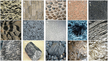
Structures of hard rocks that have experienced deformation under flow are classified as massive or fluidal or as structures exhibiting flow banding, which results from a parallel arrangement of variously colored bands, for example, of volcanic glass, phenocrysts and microlites. Depending on the quantity of gas bubbles in lavas, distinctions are made between porous, vesicular and pumiceous structures (pumices, reticulates). Amygdaloidal structures are formed by the filling of cavities with secondary minerals (quartz, opal, zeolites, carbonates). Some metamorphic rocks demonstrate a structure called foliation, caused by a preferred orientation of sheet silicate minerals. Rocks that show banded structures without a distinct foliation are termed gneisses. Rocks that show no foliation are called hornfels, if the grain size <1 mm, or granulites, if the grain size is >1 mm (see Table 1.2). In metamorphic rocks, flaccid (shattered and disintegrated as a result of a paleo landslide or earthquake) and schistose (mostly due to lineation of schist minerals along specific schistosity planes) structures occur (Figure 1.4).
Principal rock structures classified according to the type of grain contacts (a–c), void space geometry (d–h), fabric orientation (i–m) and flatness of foliation (n–p): (a) cemented pore space; (b) cemented grain contacts; (c) cemented basal bandage (structure where grains float in cement); (d) dense isotropic; (e) porous; (f) cavernous; (g) vesicular; (h) fractured; (i) chaotic orientation of fabrics; (k) parallel planar arrangement; (l) dimensionally linear fabric; (m) linear fabric; (n) flat foliation; (o) wavy foliation; (p) shear band S-C fabric.
The structure of clastic rocks depends on the mutual arrangement of grains, which can be random, laminar or fluidal. In random structures, particles do not have any ordered arrangement. This structure is characteristic of very coarse-grained rocks, such as gravel, shingle and sands, but it may also be present in certain fine-grained rocks. Random structures arise in regions of sedimentation characterized by an abundant and continuous supply of homogeneous detrital material or by a continuous rolling of particles. Laminar structures are formed by the alternating arrangement of layers, either of rocks having varying mineralogical compositions or of chemogenic layer-forming rocks (anhydrites, gypsums, rock salt, potassium salts). In laminar structures, the individual layers are distinguished from one another not only by composition but also by grain size. Fluidal structures result from deformations of the original laminar structure or the influence of water flows and landslides, or an intensive wave action, or a collapse of laminar structures. In chemical sediments, oölitic structures are very common, characterized by rounded grains or grain aggregates; these are typical for carbonate rocks (limestones, dolomites), iron, manganese, and phosphate ores and bauxites. Biogenic sediment structures in some cases result from organism build-up, the so-called growth structures. Structures of this type are characteristic of corals, bryozoans (“moss animals”), calcareous algae and hydractinians (gastropod shells). The build-up of organisms produces either a flat body lying along the bottom with a gently undulating surface (stromatolite) or a small, oval mass resembling concretions (oncolite). Bodies that grow in the shape of hills or high knolls are called bioherms (ancient organic reefs with a predominance of fossil calcareous algae). Coral reefs are usually a combination of stromatolites (columns formed by the growth of layer upon layer), oncolites (layered spherical structures) and bioherms (shapes built by marine invertebrates).
Rocks whose mineral grains are larger than 0.2 mm are grained rocks (Tables 1.2 and 1.3). In this case, it must be distinguished whether mineral grains are predominantly monodispersed or are more or less nonuniform in size. In addition to size, the shape of individual grains and minerals in rocks is an important diagnostic feature of their physical properties. Shapes of crystals newly formed and grown from solutions or melts, or from recrystallization, are determined by the shape of their neighbors. In any case, they are straight-edged or irregularly angular on margins. In contrast, mechanically transferred or transformed grains or fragments of rocks are rounded more or less well, depending on the original grain shape, transport distance or degree of strain, and hardness of the material. This is the case of many sedimentary rocks, due to the significant influence of their formation environment. Grain binding in rocks is also used to determine their mechanical properties. One distinguishes between indirect and immediate grain binding. In the case of indirect grain binding, individual mineral grains are cemented by a – usually crystalline – binder (cement). This can be of the same material as the grains themselves, or it may be a foreign material. Indirect grain binding is mainly observed in sedimentary rocks. In rocks formed by recrystallization from solutions or from melts, the recrystallization predetermines the immediate grain binding. Single crystals directly border each other here, i.e. without being cemented by an intermediary. Cohesion of rocks is preserved by interfacial forces and by a close interlocking of individual grains. The texture elements are illustrated in Figure 1.5.
| Average grain size (mm) | Description | Example |
|---|---|---|
| 30 | Granular, giant-grained | Pegmatite, graphic granite |
| 30–10 | Large-grained | Phaneritic igneous rocks: gabbro and granite |
| 10–3 | Coarse-grained | Igneous intrusive rocks: granite and gabbro |
| 3–1 | Middle-grained | Igneous: granite, syenite |
| 1–0.3 | Middle-grained | Igneous intrusive or hypabyssal rocks: gabbro, diabase, basalt |
| 0.3–0.1 | Fine-grained | Aphanitic igneous rocks: aplite, andesite, veined gneiss |
| <0.1 | Dense rocks | Igneous rocks: basalt |
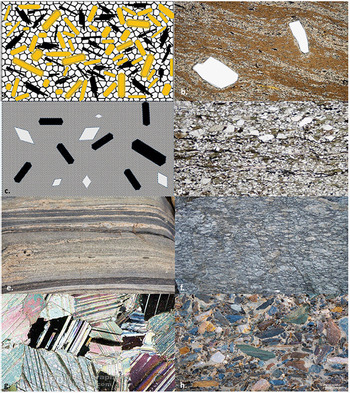
(a) Fabric or texture of granite rocks as an example of plutonic rocks. Even-grained crystals without preferred orientation: feldspars are uniform yellow; mica shows close parallel black plates; white in the remaining space is quartz. Especially, feldspars form idiomorphic crystals, while quartz is xenomorphic. (b) Fluidal texture in volcanic rocks. Crystals follow in their arrangement the flow pattern of melt. (c) Porphyric structure of igneous rocks. Crystals float in a fine-grained crystalline matrix. Large crystals had already been formed within the magma chamber. After a rapid deflation of the chamber, they were transported upwards together with melt during a volcanic eruption; this itself causes fast cooling and, therefore, results in a finely crystalline or even glass-like solidified host matrix. (d) Structure of clastic sediments. Quartz is rounded and white, mica is of an almost parallel orientation and dark, while feldspar is grey. (e) Parallel texture of gneiss as an example of metamorphic rocks. (f) Texture in eye gneiss. (g) Puzzle-like arrangement of calcite crystals in metamorphic marble rock showing twinning planes. (h) Breccia texture consisting of different rock fragments randomly cemented or compressed together inside finer-grained host material.
1.6 Global Rock Cycle
No rock exists forever, even though in continental formations the rocks have a better “chance of survival” than the oceanic ones. In the course of plate tectonics, the rock circulation has become a cycle: spreading center – subduction – volcanic eruption – sedimentation – subduction. Plate tectonics itself is a continuous rock cycle, as shown in Figure 1.6.
Rock cycle in the context of plate tectonics. Partial melting of the upper mantle peridotite rocks and further accumulation of basaltic melts in the mid-oceanic ridge magma chambers causes the growth and spreading of oceanic crust and lithosphere. Subducted oceanic crust and sediments partially remelted and partially metamorphosed in subduction zones come back to the surface in the form of diapirs or sink further with plates deeper into the mantle. The partially melted residue is sinking downward and more buoyant diapirs rising upward. This causes strato-volcanic activity, eruptions and aerosol formation. Together with rock weathering, erosion and biogenic processes, this contributes substantially to sediment formations. Rocks metamorphosed via contact and regional tectonic processes can be directly exhumed to the surface or, alternatively, form igneous rocks after partial melting or decompression melting.
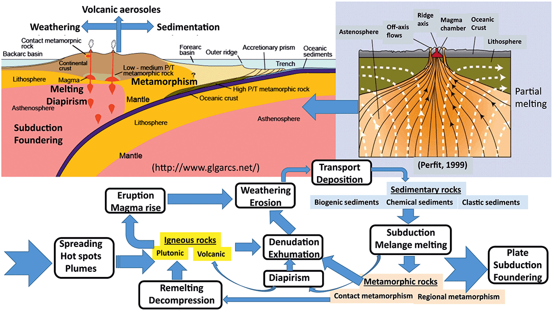
Figure 1.6 elucidates a typical plate tectonic scenario of the rock cycle concept. Considering the example of a magmatic belt above subduction zones, it is shown how the three formation processes for magmatic, sedimentary and metamorphic rocks are related to each other. The most important processes that move rocks from one to the next group are as follows: weathering, subduction and partial melting–remelting.
1.7 Basic Description of Petrophysical Parameters
Rocks are composed of mineral grains, porous space and a medium filling it. Thus, essentially, rocks are heterogeneous mineral mixtures. Nevertheless, one assumes macroscopic homogeneity of rocks and uses so-called mean values or “effective physical parameters” to characterize their properties. Physical properties in general are tensors having a certain rank, or a number of simultaneous directions, in which this property is defined and may be measured. For example, density is a scalar or a tensor of rank 0, velocity and force are vectors or tensors of rank 1, thermal conductivity, stress or strain are tensors of rank 2, and the elasticity coefficient tensor is a tensor of rank 4. So, in physics, a tensor variable characterizes the properties of a physical system depending on spatial directions, and the rank of the tensor is the measure of its spatial directions. For example, vectors and complex numbers are tensors of rank 1, piezo-electric coefficients are tensors of rank 3, etc. In physics, the definition of tensor rank comes from the number of directions that are involved in the parameter definition. For example, mass has only a magnitude and zero directions (rank 0), force and velocity possess magnitude and direction (rank 1), stress and strain are characterized by a magnitude and two directions (rank 2), magnetostriction coefficients or strains per magnetic force are determined through magnitude and three directions, two from strain and one from force (rank 3), etc.
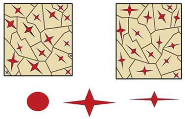
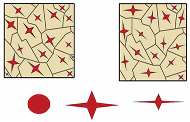
Physical media in which physical parameters do not vary in any spatial direction are called isotropic. In the case when a physical property depends on spatial directions, this medium is called anisotropic. How can this be applied to rocks? If all crystallites in a rock have the same orientation, the anisotropy of such a multi-crystal solid corresponds exactly to that of a single crystal (Figure 1.7a). In the case of random textures (Figure 1.7b), where all orientations are equally abundant, the behavior of the polycrystalline material is macro-isotropic, although each building block (crystallite) demonstrates anisotropic behavior by itself. The anisotropy of an individual mineral grain may vary depending on directions: from weak (Figure 1.7c, left) to strong anisotropy (Figure 1.7c, right). Thus, a random orientation or a perfect alignment of anisotropic grains plays a crucial role in the overall anisotropy of a polycrystalline rock.
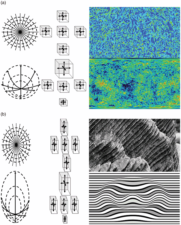
If liquid or/and gaseous constituents are constituent phases of rock (porous and fractured rocks saturated with water and gas), then the proportion of porosity, saturation or fillings of pores, their space distributions and the specific properties of these constituents have a major influence on most of the petrophysical parameters listed in Table 1.1. Thus, natural rocks represent a medium with uneven physical parameters distributed nonuniformly in space; essentially, they are inhomogeneous. The reason for this is sporadic and continuous geological processes, which have modified most rocks. These processes include mechanical deformation, melting and recrystallization, phase transformations, modifications at crystal interfaces, and nonuniform rigid particle translation and rotation. Figure 1.8a–d illustrates the principle of inhomogeneous and isotropic petrophysical parameter distribution; the physical properties differ from point to point, but this does not depend on any spatial direction at a particular locality. In this case, the petrophysical parameters may be characterized by their spatial gradients. For example, seismic wave velocities in a homogeneous planet increase as a function of depth. On the contrary, anisotropic properties of multi-crystalline rocks, such as plasticity, elasticity, hardness, strength, elastic wave splitting, thermal expansion coefficient, thermal and electrical conductivity, magnetization, corrosion resistance to fluids and water, optical properties, etc., at any locality inside a rock may depend on spatial direction. This may be due to a specific alignment of mineral grains having a particular geometric form, or it may be due to anisotropic physical properties of grains themselves. In this case, the gradients of properties are negligible but the properties depend essentially on spatial direction (Figure 1.8c–d, middle panel). Rock homogeneity and isotropy are scale-dependent quantities, and they are determined by the spatial resolution scale on which the measurements have been conducted.
Illustration of the terms (a) “isotropy + homogeneity”: the image of homogeneous and isotropic turbulence at Rayleigh number 230; (b) “isotropy + inhomogeneity”: the mass distribution in the Universe; (c) “anisotropy + homogeneity”: layered shale rocks; (d) “anisotropy + inhomogeneity”: corrugated image of a layered structure.
1.8 Granular Analysis in Rocks
Grain size analysis is the most important property of clastic sediments and crystalline rocks in general (Tables 1.2 and 1.3). Porosity and permeability, as well as mechanical properties such as compressibility and thermal expansion, are in principle particle size dependent. There are a few methods to perform rock grain size analysis:
a) Sieve analysis using a set of sieves with mesh size usually differing by a factor of 2 from 0.02 to 4 mm. When performing sieve analysis, one defines the particle diameter as the side length of a square mesh through which grains may pass.
b) Image analysis of thin sections combined with the stereological correction of particle size statistics. Making black and white images of thin sections, one discriminates a particular mineral and then, using image analysis software, defines various geometric parameters of grains by counting pixels on binary images.
c) Laser grain size analysis, whereby the size of particles suspended in a solution is estimated from a form of diffraction patterns measured by a laser beam passing through a transparent cuvette. The typical working range of particle sizes is 0.16–1250 µm.
d) The pipette method is based on the categorization of particle sizes from their sedimentation velocities in a solution with known density and viscosity. Particle diameters are defined as an equivalent size to that of a sphere settling in the same liquid with the same settling velocity as the tested particles. The measured particle size will be the so-called Stokes diameter.
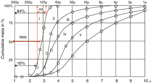
The results of grain size analysis are usually presented as a graph of the percentage of particles having a size lower than a certain value, i.e. the integral or cumulative curve, or having sizes between two values, i.e. the distribution curve. Figure 1.9 illustrates cumulative curves of size distribution in sands. The units of size may be either mm or  –units. One defines the unit
  , where d is the grain diameter. Two principal characteristics of cumulative and distribution curves are the statistical central value and dispersion of grain sizes. The median
  is the particle size (in mm or
  ) in which particles larger than
  and particles smaller than
  occur equally (50 vol.%):
  at the 50th percentile. The “mean” is the average grain size, which can be calculated by
  . The sorting
  corresponds to
  and is a measure of homogeneity, where the 84th, 16th, 95th and 5th percentiles of the grain size distribution are in
  -units. This value is also called the Inclusive Graphic Standard Deviation. Very often, one uses a simpler formula,
 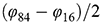 . When
  , the particle size is very poorly sorted; if
  the grain size is very well sorted. Usually, these two characteristics,
  and
and  , are used when data are presented graphically. Calculating moments of grain size distributions is a nongraphical way of determining grain size statistics. The number of particles that belong to certain size interval is called the statistical weight. The computations of statistic moments involve multiplying a weight frequency in percent by a distance from the midpoint of the size distribution. Two principal statistic moments are skewness and kurtosis. Skewness is the degree of asymmetry of a grain size distribution relative to its midpoint:
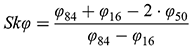 (1.1)
(1.1)Kurtosis is a measure of the grain size sorting far away from the central part compared with the sorting close to the midpoint:
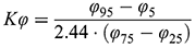 (1.2)
(1.2)The normal or Gaussian distribution curve (see Focus Box 1) is characterized by  in
in  -units. So, kurtosis indicates an excess or a deficiency of the central part of distribution relative to the normal distribution, i.e. the random distribution of grain sizes.
Determination of median and sorting using cumulative mass of particles having size larger than a certain size in φ-units. Data for five sand deposits of Barataria Bay sediments (linear φ-scale). i – shallow water sands; ii – sands deposited by string currents; iii – sand deposits at current edges; iv – silts; v – sand deposits formed far away from current edges (data after Reference Krumbein and AberdeenKrumbein & Aberdeen, 1937). Lower abscissa axis is in φ-units, upper abscissa axis is in µm:  , where D0 in this case is 1 mm at φ = 0.
Other characteristics of grain analysis include aspect ratio, roundness/angularity, and flatness and elongation ratios of grains. Flatness ratio (p) is the ratio of the shortest length (thickness) to the mean length (width) of a grain. Elongation ratio (q) is the ratio of the mean length to the longest length (L). By combining the flatness and elongation ratios, particle shapes of an aggregate can be described by the shape factor (F): F = p/q.
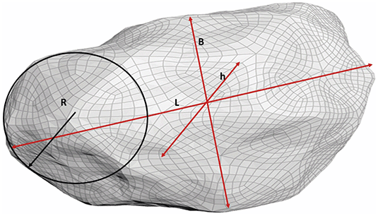
From the dispersion and mean size derived from the cumulative curves in Figure 1.9, one can conclude how rivers work to produce rounded gravel particles, which is important for quantification of estuary products. At differing degrees of closeness to the current edges, the cumulative curves look different. The shapes of sediment particles may vary also. The question arises: how does a particular gravel grain differ from an ideal spherical shape? For this, the index of roundness/angularity, defined as Rn = 2R/L * 100, and the index of flatness, given by f = (L + B)/2h * 100, are introduced (see Figure 1.10).
Sketch of characteristics of roundness/angularity and flatness of gravel grains: L is the largest Feret diameter of 3D grain, B is the largest Feret diameter orthogonal to L, h is the largest Feret diameter in orthogonal to R and L, and R is the maximum possible diameter of an inner half sphere that is tangential to the grain surface.
In some image analysis software, the definition of roundness/angularity index  is introduced through the ratio of effective area A to perimeter Π of imaged grains:
 (1.3)
(1.3)The convex hull or convex index of grains represents the minimum convex geometry that encloses a grain. Thus, the convex perimeter (Πc) of a grain is smaller than the actual perimeter (Π) obtained from grain image analysis. The roughness index (ℜ) of grains can be estimated by the ratio ℜ=Π/Πc. The sphericity index (Ψ) is defined as the ratio of equivalent surface area of a sphere having the same volume as an aggregate grain. Sauter mean diameter (ds) is defined as the diameter of a sphere that has the same volume/surface area ratio as a particle of interest. In 2D image analysis, it is sometimes replaced by the simple area/perimeter (A/Π) ratio.
1.9 Grain Boundaries in Rocks
In solid rocks, mineral grains have contacts with neighbors and with porous space. These contacts are called grain boundaries (GB), and sometimes they are found to possess specific physical properties differing from the bulk of grains. In this case, grain boundaries appear to have an appreciable width, much smaller than the sizes of grains. Thermodynamically, grain boundaries possess an excess of lattice free energy and entropy, since arrangements of atoms close to the surface are more chaotic and there is a lack of neighboring lattice atoms.
Grain boundaries can be considered either as mechanical contacts where grains of differing minerals meet in a solid, or as transition regions between neighboring crystals of the same or another kind, or as planes and surfaces where there are some disturbances in the atomic packing of a crystal, or as contact surfaces of minerals with gas or fluid filling pore and fracture spaces. At high temperatures, grain boundaries become mechanically weak; they lose their strength more rapidly than crystals do. This results in fracturing of rocks and the appearance of microcracks, which no longer traverse the crystal interior but rather, run along the grain boundaries. Fractures and voids of this type are called intergranular.
The main characteristic of granular solids is a specific surface of grain boundaries per volume or per mass unit, defined as follows:
 (1.4a)
 (1.4b)
 (1.4c)
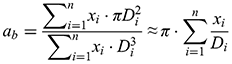
where D is the diameter of equally sized spherical grains and ρ is the apparent density of grain material. How to describe the specific surface of grains in the case of a grain size distribution? In rocks consisting of grains having n various grain sizes and various specific surface areas agi, the specific surface area of all grain fractions can be given as follows:
The total number of grains or pores in a sample can be denoted by N (m−3), and the number of grains having a size between D and D + ΔD is x (m−1∙m−3). The relationship between the total number of grains per volume N and the grain size distribution x(D) is given by:
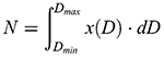 (1.6).
Grain surface is equal to the surface of grain boundaries, surface area is in m² per unit volume in cm³ (adapted from Reference Guéguen and PaulciauskasGuéguen & Palciauskas, 1994). Naked eye estimations; image analysis using optical and scanning tunneling microscopes permits the specific surface to be estimated in rocks up to 100 m² cm−³.
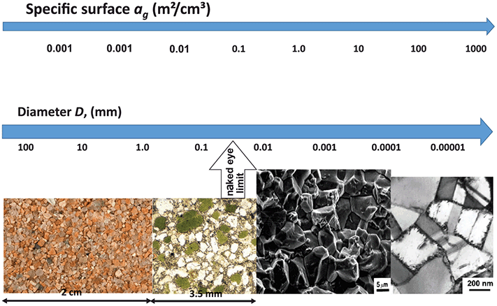
Besides image analysis methods for specific surface measurements in rocks, there are Brunauer–Emmett–Teller (BET) (see Focus Box Chapter 2) and different gas absorption methods operating in the range 2.5–250 m² cm−³, nuclear magnetic resonance (NMR) methods measuring the decay time of an induced nuclear spin, mercury intrusion porosimetry (in the range 1–106 m² cm−³), computed tomography (CT) X-ray (2.5–500 m² cm−³) or laser diffraction (300–3∙108 m² cm−³) on inhomogeneities, capillary flow porosimetry (104–108 m² cm−³, etc. Gas absorption methods or gas pycnometers are designed to estimate a true specific gravity using the principle of adsorption of a flowing gas (for example nitrogen). The principles of some of these methods will be discussed in Chapter 2.
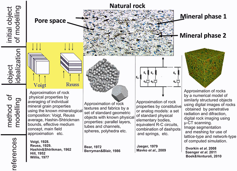
Theoretical description of physical rock properties is essentially based on model concepts for a particular rock type. Figure 1.12 schematically represents four different approaches to modelling the physical properties of rocks. The models differ in the idealization approaches of “rock structure.” The first column from the left explains the so-called averaging models of rock properties by calculating effective parameter bounds in rocks as mineral phase aggregates. The second column from the left gives an idea of the rock idealization model by approximating the geometry of minerals and pore spaces with standard object geometries, like cylinders, spheres or bricks. The third column from the left represents constitutive analog modelling, where rocks are considered as combinations of standard physical elements like springs, dash-pots and constant friction elements to describe the mechanical properties of a rock, or like resistors, capacities and constant phase elements to describe electrical properties, etc. The fourth column from the left represents numerical methods to describe rock properties by taking nondestructive 3D images of minerals and pores in an intact rock sample and computing physical characteristics with the use of finite element methods or lattice- and network-type approaches.
Classification of theoretical descriptions of physical rock properties.
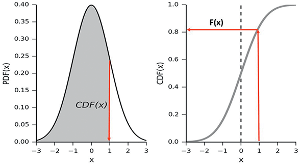
1. The probability density function (PDF) is the probability p(x)∙dx to find a continuous random variable x between two values x and x + dx, where p(x) is the probability density (per interval dx). Thus, the probability to find a variable x within a finite interval (b, a) is given by:
 (FB1.1)
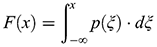
2. The cumulative distribution function (CDF) is the probability F(x) to find a variable x having a value less than or equal to a given x. That is given by
where ξ is an integration variable.(FB1.2)In Figure FB1.1a the shadowed area beneath the PDF curve corresponds to the value of the CDF F(x) shown in Figure FB1.1b. The whole area beneath the p(x) curve on the left corresponds to the probability =1 of the event to find a random variable x at any possible value (−∞, +∞).
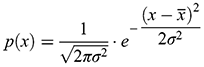
3. If the number of random events is very large, then the Gaussian distribution function may be used to describe statistics of physical events. Mathematically, p(x) for the Gaussian or normal density distribution function is given by:
(FB1.3)4. This distribution depends on two parameters, the mean value of the variable
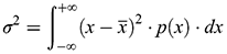
and the standard deviation from the mean value σ (the variance is σ²). The full width 2Δx of the Gaussian curve at half of the maximum value is calculated from
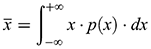
(FB1.4)and is given by 2Δx = 2 √ln(4) σ ≈ 2.355σ. The interval () under the Gaussian PDF curve contains about 68.2 percent of the whole area. This means that 68.2 percent of x random values fall within this interval.5. The mean value
is the first moment of the PDF and may be calculated from the integral
(FB1.5)The variance σ² is given by the second moment of the PDF:
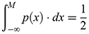
(FB1.6)The median M is the abscissa point corresponding to 50 percent of the area beneath the PDF curve:
(FB1.7)The most probable value of the random variable corresponds to the abscissa point of the PDF maximum.
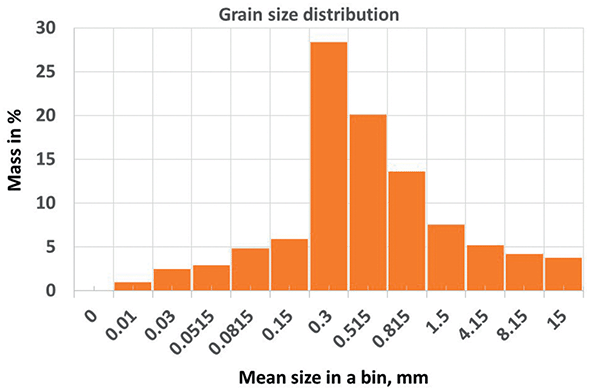
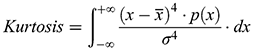
6. In reality, the PDF p(x) may be very different from the Gaussian or normal distribution. For example, in Figure FB1.2 the grain size distribution from Exercise 9 is presented. The horizontal axis is the mean size of particles in a particular bin. The axis is not linear; it is logarithmic, and the PDF of grain sizes is p(log(d)); thus, it has to be compared with the log-normal distribution function. There are two parameters that quantify deviations of measured p(log(d)) from the log-normal PDF: (1) the lack of PDF shape symmetry and (2) the ratio deviation of peak height to peak half width from the same ratio of the PDF. These two parameters are called skewness and kurtosis, and they are defined as the third and fourth moments of the PDF:
(FB1.8)andSkewness may be positive or negative, and for symmetric PDF functions it is 0. Kurtosis for the Gaussian PDF is 3, and the deviation of the actual kurtosis from 3 is called the kurtosis excess. If the excess is negative, the PDF possesses light-weight tails in respect to the normal PDF; if the excess is positive, the tails are heavier than for the normal PDF.(FB1.9)For the grain size distribution from Exercise 9, the calculated parameters of grain size PDF are as follows.
0.52 1.99 Skewnessφ −0.40 Kurtosisφ 3.60






PDF p(x) and CDF F(x) functions.
Example of grain size distribution.