


1. Introduction
Additive manufacturing (AM) is experiencing a gain in relevance within both industry and research domains, particularly in the context of Material Extrusion (MEX), especially Fused Layer Modeling (FLM) for the fabrication of components from thermoplastic materials. AM offers a high degree of design freedom, enabling the fabrication of complex geometries with relatively short lead times. Notably, the expenses associated with AM are lower when producing small quantities in comparison to conventional manufacturing techniques, such as injection molding or subtractive machining. Nevertheless, there are major limitations in the mechanical, thermal, and functional properties of the parts produced. In addition to the general restrictions to the fields of application due to the material properties of polymers, the anisotropic component properties are also often considered disadvantageous for technical products made in layer-by-layer manufacturing processes (Reference Pei, Bernard, Gu, Klahn, Monzón, Petersen and SunPei et al., 2023). The manufacture of a functional component requires an advanced understanding of process anisotropy (Reference Fischer, Achten and LaunhardtFischer et al., 2023). A reduction of this anisotropy is essential if FLM-parts should be used in structural components and serial production applications.
The anisotropy of components manufactured in sequential layers becomes apparent in the fact that FLM-parts do not have equivalent mechanical properties in all spatial directions. In most cases, the components demonstrate a substantial reduction in strength and stiffness along the building direction (Z-axis) relative to the deposition direction of the material strands (XY-axis). Furthermore, adjacent extrusion paths exhibit a substantially weaker bond when compared to a single path. Consequently, the direction-dependent strength exhibits a strong correlation with the orientation of the component during the construction process (Reference Gao, Qi, Kuang, Su, Li and WangGao et al., 2021). While a continuous strand is deposited in the printing direction, the strength in the building direction depends on thermal diffusion between the individual layers (Reference Pei, Bernard, Gu, Klahn, Monzón, Petersen and SunPei et al., 2023).
The thermal input during printing process directly affects the strength in the build direction by promoting fusion and diffusion between layers and strands. It depends mainly on printing temperature, cooling, and printing speed represented by the moving velocity of the printer’s nozzle (feedrate) as the print speed determines how much heat is distributed into the substrate. Reference Akhoundi and HajamiAkhoundi and Hajami (2022) found, that with increased printing speed the tensile strength of parts is reduced. Reference Giri, Chiwande, Gupta, Mahatme and GiriGiri et al. (2021) found a reduction in tensile strength in the vertical direction with increased cooling power and demonstrated directional dependence. Reference Hashemi Sanatgar, Campagne and NierstraszHashemi Sanatgar et al. (2017) showed a linear effect of extrusion temperature on bonding between 3D-printed PLA and PLA-fabric due to enhanced diffusion between the layers. Other studies also investigated optimal manufacturing parameters (Reference Mohamed, Masood and BhowmikMohamed et al., 2015; Reference Spoerk, Arbeiter, Cajner, Sapkota and HolzerSpoerk et al., 2017; Reference Suniya and VermaSuniya & Verma, 2023). Reference Ahn, Montero, Odell, Roundy and WrightAhn et al. (2002) examined anisotropy in ABS parts, emphasizing that infill orientation strongly influences component strength and with that anisotropy. Reference Grant, Regez, Kocak, Huber and MooersGrant et al. (2021) confirmed a strong dependence of strength on build direction for ABS and PLA specimens. Reference Chacón, Caminero, García-Plaza and NúñezChacón et al. (2017) and Reference Rodríguez-Panes, Claver and CamachoRodríguez-Panes et al. (2018) examined the dependency of anisotropy on feedrate, layer height, print orientations and infill densities.
This paper presents a new concept of path planning strategy for adjacent strands in FLM-printing. The new design idea is to print a flat spiral instead of adjacent strands. This could reduce anisotropy and increase parts strength in building direction because of increased temperatures in the depositing area.
2. State of the art and new design approach
There are different approaches in science and industry to reduce anisotropy in FLM-parts. All options can be subdivided in three categories: material improvement, process improvement and machine improvement.
2.1. Material improvement
In addition to adjusting material properties through compounding by the filament manufacturer, another way to improve parts strength and reduce anisotropy is to anneal components after production. By reheating components above the glass transition temperature, amorphous structures in PLA, for example, are converted into crystalline structures, and a new diffusion process between the individual strands and layers can be triggered, which further increases the mechanical strength between them. Such investigations were carried out by Reference Kahya, Tunçel, Çavuşoğlu and TüfekciKahya et al. (2025), Reference Pazhamannil, Krishnan and EdacherianPazhamannil et al. (2022), Reference Kartal and KaptanKartal and Kaptan (2023) and Reference Jayanth, Jaswanthraj, Sandeep, Mallaya and SiddharthJayanth et al. (2021), who observed an improvement in mechanical properties. Reference Hulea, Stefan, Kiss and AriesanHulea et al. (2025) were able to demonstrate a reduction in anisotropy in their investigations. The tensile strength of the samples in the build direction was improved by 19-28%.
Reference Shaffer, Yang, Vargas, Di Prima and VoitShaffer et al. (2014) investigated a special possibility for improving the layer bonding in a post-processing step. They tested how subsequent irradiation with gamma radiation affects the mechanical properties of sample bodies (crosslinking). The increased temperature resulting from the irradiation particularly supported the crosslinking of PLA. The difference in tensile strength between the build and deposition directions was reduced from 32.3 MPa to 14.0 MPa, thereby also reducing the anisotropy.
2.2. Machine improvements
One approach to reduce anisotropy by adapting the printing system was presented by Reference Bengfort, Stracke and KünneBengfort et al. (2021). They established a rotary printhead, to pre-heat the substrate material with a laser-ray while integrating an impact-cooler to improve the cooling of the deposited material. With this printhead they examined the distortion and tensile strength of specimen made of PP in comparison with standard extruders. The new system was able to enhance the mechanical strength in building direction. Similar approaches were performed by Reference Deshpande, Ravi, Kusel, Churchwell and HsuDeshpande et al. (2018) and Reference Han, Tofangchi, Deshpande, Zhang and HsuHan et al. (2019). Reference Yu, Jing, Yang, Wang, Zhang and LiYu et al. (2022) developed a printing system, to induce a rotary shear-stress-field in the deposition region. With this, they were able to enhance the inter layer bond from 21.1 MPa to 59.3 MPa. Consequently, they could reduce the anisotropy from 0.41 to 0.09. The compression of the deposited layers by passing over them with a heated roller was also investigated. Reference Andreu, Kim, Dittus, Friedmann, Fleischer and YoonAndreu et al. (2022) modified a conventional 3D printer to examine the layer bonding of the printed part by “hot rolling” at different temperatures, contact pressures, and speeds. The system achieves a maximum increase in component strength of 38.8%. Another machine-sided improvement is printing on a vibrating build platform. Reference Aihemaiti, Jiang, Aiyiti, Wang, Dong and ShuaiAihemaiti et al. (2024) obtained an improvement in the mechanical properties of HA-PLA and PLA using a vibrating print bed in the ultrasonic range. Micrographs showed a reduction of air gaps between adjacent paths, resulting in better welding. The arrangement and size of the internal defects was additionally analyzed by a CT analysis, which showed a reduction in porosity as a result of the vibration.
2.3. Process improvement
In the context of this work, process improvements are those that do not require any further modifications to the printing system itself, but can be applied independently of the machine by adjusting for example the parameters or the deposition strategy. Optimization of various mechanical properties by adjusting different process parameters or slicing parameters, such as grid orientation, layer height, or printing temperature, has already been carried out with many different optimization strategies for different materials (Reference Dev and SrivastavaDev & Srivastava, 2021; Reference Mishra, Malik and MahapatraMishra et al., 2017). Saberton describes a current idea for improving the layer bonding in FLM and thereby achieving higher isotropy in his patent No. US 11,813,789 B2. This involves so called “bricked layers.” Here, the layers are printed with a periodic offset in one spatial direction so that the tracks overlap (Mark Reference SabertonSaberton, 2023). Reference Rangelov, Stojanović, Miltenović, Aranđelović and PerićRangelov et al. (2025) investigated a similar method and came to the conclusion that the use of bricked layers can increase the layer bonding of PLA test specimens from 22.14 MPa to 23.2 MPa. They also investigated the impact of higher flow-rates on layer adhesion and found a positive effect for either bricked layer and conventional path-design.
2.4. New design approach
Besides the bricked layers strategy this paper considers another process improvement in the form of a novel deposition strategy for adjacent paths, as they occur primarily at the perimeters of FLM-parts. Conventionally, the paths are deposited parallel to each other, which is why there is often no full-surface contact between the strands (Figure 5, 20L5). The novel approach involves laying down a continuous, flat spiral, which creates the corresponding total path width (see Figure 1). In theory, this addresses several weaknesses of the conventional process. On the one hand, the nozzle remains in one segment for a longer period of time, which is intended to improve the fusion of the overlapping paths. The rapid spiral movement of the nozzle creates a larger melt pool, which results in a more homogeneous connection between the layers. Various publications show a correlation between induced thermal energy and improved component strength. The aim of this work is to improve the mechanical properties of FLM-printed parts in Z-direction (building direction) and consequently reducing the anisotropy. Another aim is to build up a part with less voids, which leads to more homogenous material properties. This paper presents the developed concept and, in an initial investigation, demonstrates the suitability of the novel technique by characterizing the mechanical properties in tensile and bending tests.
Visualization of the different extrusion strategies

3. Methods and materials
To analyze the impact of the new design of path planning in FLM a new G-Code generator needed to be developed. After defining test scenarios, the samples are printed and then tested. Tensile tests and bending tests are performed to analyze the anisotropy of the components. The necessary methods and materials are described in this chapter.
3.1. G-code generation
To enable a 3D printer to deposit continuous spiral toolpaths, a custom G-code must be generated that encodes the desired trajectory. For this purpose, a Python-based generator was developed to produce the machine code as a function of user-defined geometric and process parameters. Initially, a base geometry is constructed to define the shape of the object. Two separate subroutines were implemented: one that generates a rounded rectangle with adjustable parallel length and corner radius for tensile test blanks, and another that produces a simple line contour for bending tests. With the centerline of the geometry established, the print paths are generated around this central axis in each layer, ensuring that the layers stack up to form a vertical wall.
The first layer is generated using conventional parallel toolpaths to ensure reliable bed adhesion. For subsequent layers, a continuous spiral path is computed. The spiral width is defined as the path width with the nozzle diameter subtracted. Because the center of the nozzle follows this path, the resulting deposition yields a wall of the intended nominal thickness. The distance between spiral loops and therefore the number of self-intersecting extrusions is governed by the oscillation pitch, path width, and nozzle diameter parameters. The number of points per loop can also be set, with higher values increasing the resolution of the spiral, leading to finer, more detailed circles. However, this also results in a larger file size and likely longer print times, as more movement commands are required to guide the nozzle through the additional spiral points.
An optional “alternating layer” mode is also implemented. In this configuration, a secondary spiral path is generated with reversed rotational direction and a 180° phase shift. The resulting pattern interlaces consecutive spirals such that the loops of one layer align with the gaps of the previous one (Figure 1). This alternation between even and odd layers is supposed to enhance path uniformity and improve interlayer bonding in the printed structure.
3.2. Used materials
For the investigation tensile and bending specimens were produced from polylactide acid (PLA)-filament. An uncolored material was chosen, as color pigments can have an influence on the mechanical behavior of the material (Reference Frunzaverde, Cojocaru, Bacescu, Ciubotariu, Miclosina, Turiac and MargineanFrunzaverde et al., 2023; Reference Gao, Xu, Xu and LiuGao et al., 2022; Reference Wittbrodt and PearceWittbrodt & Pearce, 2015). The PLA used is sold by Filamentworld and has a diameter of 1.75 mm. It was dried before printing using an active heating filament dryer and was also stored in the heated environment while printing. The tensile and bending specimen were printed with separate filament spools to make the results within one test scenario more comparable.
3.3. Printing
To produce the specimen a Delta Wasp Industrial X from Wasp S.r.l. was used. This is an FLM-3D-printer with delta kinematics and a closed build environment. This makes tests more repeatable and reliable, because ambient conditions (e.g. draught, ambient temperature) effect the print less. The use of a closed build environment is not usual for printing PLA. In addition, all prints were done with part cooling turned off. The G-Code files for the reference specimen were generated using Prusa Slicer with a printer profile developed in-house, because for the printer used there is no stock-profile in Prusa Slicer available.
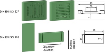
After printing, some of the specimen must be cut out of the blanks (Figure 2). Only the standing bending-specimen are printed directly in batches of two in each print job. All remaining blanks were printed as a rounded rectangle, where the specimens are cut out of the long sides. The laying bending specimens are cut out using a band saw. To avoid defects in the test area, an additional distance to the sample length was maintained. Therefore, the length of the bending specimen was raised to 55 mm. The tensile specimens are also cut out of the long sides of the rectangle. Because of the complex shape a CNC waterjet was used to cut the specimen of Type DIN EN ISO 527-2 1BA out. For every rounded rectangle one set of five laying (XY-direction) and one set of five standing (Z-direction) specimen were cut out. The building direction and dimensions of the specimen are also shown below (Figure 2).
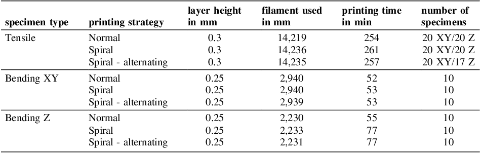
The self-developed python script, which generates the spiral-G-Codes, uses an ideal calculation for the amount of filament. To make sure the tests are as comparable as possible, the filament used for the reference specimens was adjusted by increasing the flowrate to 103.2% in Prusa Slicer. The printing time was adjusted as well using the maximum volumetric speed in the slicer settings. A volumetric speed of 2.1 mm3/s was used. The following table (Table 1) shows the used settings, the resulting filament lengths and printing times. Only in case of the standing bending-specimen the printing time is not adjusted correctly because the dynamics of the used machine differ at the edges of the build area from those in the center. All specimen were printed with 215°C nozzle temperature and 60°C printbed temperature. The nozzle diameter during all tests was 0.4 mm.
Overview of printing parameters and number of specimens

Orientation and geometry of blanks/specimens

3.4. Mechanical testing
All mechanical tests were performed on a Quasar 25 universal test machine from Galdabini. Different devices were used to perform the test scenarios. The strain is measured using the crossbeam path, because the tactile extensometer of the machine often notches the specimen and so it might fail earlier. This work focuses on the comparison of the strength values. The measured strain values are therefore not comparable with other studies and should be regarded as purely qualitative. A test velocity of 5 mm/min is used for all tensile tests and for the bending tests the crossbeam velocity is 1 mm/min. All tests were conducted under normal, constant room conditions.
4. Results
All samples and sample blanks could be produced flawlessly on the FLM-system. The surface structure created by the spiral-shaped print head movements differs noticeably from that of conventional FLM-parts. Figure 3 shows an image of the surface structure of a conventionally printed and an object with spiraled toolpaths. The layer direction is no longer clearly visible on the objects printed in a spiral or alternating spiral pattern. This results in a regularly structured surface. The spiral printed objects without alternating layers show a rougher surface texture on one side.
To evaluate the new technology, tensile specimens are tested in accordance with DIN EN ISO 527. For evaluation purposes, the tensile specimens are averaged across all tests, whereby it should be noted that the number of test specimens is not the same due to incorrect specimen cutting (Table 1). In addition, one specimen from the spiral-alternating specimens in the XY-direction was excluded from the evaluation because it cracked in the clamps.
Surface structure of conventionally and spirally printed specimen

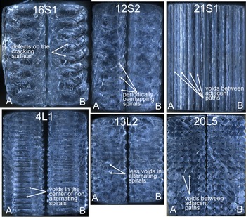
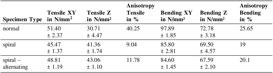
The tensile strength in the direction of deposition decreases by 11.5% from 51.4 MPa to 45.47 MPa due to the use of the new deposition strategy without alternating spirals. The samples with alternating spirals show higher strength. At 48.81 MPa, it is approximately 5% lower than the conventionally manufactured reference samples (Figure 4). Examination of the fracture edges provides information about the reason for the lower strength. Periodic stirring causes voids to form in places in the direction of deposition (Figure 5). Voids also form between the strands in the conventionally manufactured test specimens. The greater effect of the new deposition strategy is expected in the layer bonding (Z-direction). Here, too, test specimens were manufactured and tested. The results show an increase in tensile strength from 30.71 MPa for the conventional reference specimen to 41.36 MPa (spiral) and up to 43.06 MPa for the spiral-alternating variant. Figure 4 shows the results of the averaged tensile stress values for the different specimen types. The results can be found in Table 2. The fracture surfaces of the tensile test specimens in building direction (Type S) show less voids compared to the regularly printed ones (Figure 5, 12S2 and 21S1).
Left: tensile test results; Right: three-point-bending test results

In addition to the unidirectional tensile tests, the new path planning strategy is also to be tested in bending tests in accordance with DIN EN ISO 178. For this purpose, the specimens were prepared as shown in Figure 2. The distance between the supports in the three point bending tests was 32 mm. The results were averaged for each type, as with the tensile tests, and are shown with the standard deviation in Figure 4.
Fracture edges of tensile specimens (16S1, 4L1 spiral, 12S2, 13L2 spiral-alt., 21S1, 20L5 normal), fracture edges marked with A and B; S = deposition direction, L = building direction

Strength results and resulting anisotropy

5. Discussion
The tensile test results indicate a reduced anisotropy accompanied by a considerably increase in strength along the build direction when applying the new deposition strategies. To substantiate the results of the reference specimens, several studies discussed in chapter 1 can be consulted. The reproduced anisotropy of approximately 40.25% falls within the same range as other investigations (Reference Chacón, Caminero, García-Plaza and NúñezChacón et al., 2017; Reference Rodríguez-Panes, Claver and CamachoRodríguez-Panes et al., 2018).The reduction in anisotropy achieved through the novel path planning is only marginally attributable to the slightly decreased strength in the deposition direction and is primarily driven by the strength gain along the build direction. The improved interlayer bonding can be explained by enhanced diffusion across strand boundaries due to locally increased thermal energy input resulting from the oscillating motion of the hot nozzle. Examination of the fracture surfaces reveals that no distinct strands are recognizable within a single layer (Figure 5, 13L2). The deviations in the building processes with regard to printing time and material quantity are considered minor in relation to the total time and material requirements. Even though these fluctuations may have an impact on the mechanical properties (Table 1). Some deviations may also be caused by different heating times due to consecutive prints.
Examination of the fracture edges also provides information about why the samples in the XY plane are less strong than the reference sample. As can be seen, when the spirals overlap, a new weak point is formed at which the component will later fail (Figure 5, 12S2, 4L1). Since no optimization of the spiral parameters has taken place so far, it can be assumed that the strength values in the deposition direction can be further increased by means of a parameter study. Further variation of the printing speed or the nozzle diameter is also conceivable in order to more strongly induce the effect of a widened melt pool.
The use of the spiral mode without alternating layers results in a rough surface texture on one side of the strand. This can be attributed to an uneven material distribution when non-alternating spirals are employed (Figure 1). This effect can be mitigated by alternating the deposition paths, as the material distribution shifts and reverses in the subsequent layer. The tensile tests reveal improved results for specimens produced with alternating spirals. To analyze the significance of the difference between the spiralized and spiralized-alternating bending test results a T-Test was done. The p-values of both tests are about 0.25. This means there is no significance between the two series. Therefore, future studies should focus on the alternating spiraled tool paths, because of its better performance in tensile tests and the more homogenous material deposition. The fracture surfaces of the non-alternating spiral printed specimens show larger voids between the layers (Figure 5, 4L1). The alternating methods closes these gaps better, which is the reason for improved tensile strength in deposition direction. The picture of specimen 16S1 (building direction) shows some defects, which may cause from the oscillating nozzle crossing solidified material (Figure 5, 16S1). This appears in both, the spiral and spiral-alternating specimen, but only in the weaker ones.
A limitation of the new path planning strategy is the printing speed. In recent years, FLM-printing has become increasingly faster due to advancements in printing systems and control software. The developed method does not yet follow this trend, as it reduces printing speeds in comparison to conventional slicing processes. Further research is therefore required to explore and optimize the parameter space of spiraled path deposition.
The test setup presented in this study shows some simplifications and boundary conditions, which have to be examined in further studies. A closed build environment without any cooling was used to process PLA filament. PLA has a low glass transition temperature (about 60°C) and the experimental setup causes high ambient temperatures and consequently low cooling rates, which leads to better diffusion within the polymer. Also, the heated bed of 60°C might cause a higher ambient temperature in the lower layers of the specimen. The same tests might show better results without a closed print chamber, lower bed temperature and with cooling turned on.
6. Conclusion and outlook
The conducted investigation demonstrates that a novel deposition method for adjacent tracks in the FLM-process can achieve increased tensile strength along the build direction (Z-direction). Low strength in the build direction, and consequently high degrees of anisotropy, are common limitations of the FLM-process. The design approach examined in this study directly addresses this weakness. The new deposition strategy reduces anisotropy by increasing the strength of printed PLA tensile specimens along the build direction by up to 40%, while decreasing it in the direction of deposition by 5%. This results in a reduced anisotropy of 12%. Since no additional hardware or special materials are required, this technique can be applied by any FLM-user with existing equipment.
Future research should focus on optimizing the parameters of the spiralize approach to evaluate its full potential. Particularly valuable will be an analysis of defect distribution across different parameter sets, as it is plausible that variations in oscillation pitch and spiral radius influence the shapes and arrangements of the voids. Such investigations could, for example, be conducted using computed tomography. Due to the curved path deposition and increased thermal energy input, there is also potential to reduce process-related issues such as warping in more technical materials (e.g., ABS or PA12).
To achieve easy slicing of functional components with the presented strategy extensive software implementation – in regular slicing software – is required. Further improvements to the technique, followed by its transfer to realistic additive manufacturing parts, enable the production of higher-quality parts using FLM and supports its integration into new application scenarios like the lightweight construction or series production with increased strength and reduced anisotropy.




 Open access

