


Nomenclature
- BLI
-
boundary layer ingestion
- CFD
-
computational fluid dynamics
- ${c_p}\left( {J/kg/K} \right)$
-
heat capacity at constant pressure
- CP
-
power coefficient, overall efficiency
-
${C_x}$
$\left( {m/s} \right)$
-
mean axial velocity at the fan inlet plane
-
$DC60$
-
distortion index
-
$D{P_\theta }$
-
sector screen pressure loss factor
- E
$\left( W \right)$
-
shaft power
-
$F_N\left( N \right)$
-
net thrust
- K1–K5
-
traversing planes
-
$\dot m$
$\left( {kg/s} \right)$
-
fan mass flow
- NR
$\left( {rpm} \right)$
.
-
corrected shaft speed
- NRC
-
National Research Council, Canada
- OGV
-
outlet guide vane
-
$\Delta {P_t}$
$\left( {Pa} \right)$
-
difference in total pressure from a reference total pressure
-
$P,{P_t}$
$\left( {Pa} \right)$
-
pressure and total pressure, respectively
- P1i–P5i
$\left( {Pa} \right)$
-
wall pressure measurement locations at the inner wall
- P2o–P4o
$\left( {Pa} \right)$
-
wall pressure measurement locations at the outer wall
- PR
-
fan pressure ratio, total-to-total from K4 to K2
- TP1–TP5
-
test points 1 to 5 identifying operating conditions
-
$u,v,w\;$
$\left( {m/s} \right)$
-
velocities in Cartesian coordinates
-
${U_m}$
$\left( {m/s} \right)$
-
blade linear velocity at mid span
- URANS
-
unsteady Reynolds’ average equations
-
$V$
$\left( {m/s} \right)$
-
effective velocity
-
$x,y,z\;$
$\left( m \right)$
-
Cartesian coordinates
-
$\Delta {h_t}/U_m^2$
-
work coefficient
-
${C_x}/{U_m}$
-
flow coefficient
-
${\tilde \phi _K}$
-
mass flow average of a variable
$\phi $
at plane K -
$\rho \;$
$\left( {kg/{m^3}} \right)$
-
density
-
$\eta $
-
fan efficiency
-
$r\;,\theta $
$\left( m \right),\left( ^\circ \right)$
-
cylindrical coordinates
-
$\Delta \theta $
$\left( ^\circ \right)$
-
sector size


Subscripts
- Inf
-
free stream
- E
-
fan inlet
- J
-
jet
1.0 Introduction
Turbomachinery design relies heavily on (computational fluid dynamics) CFD methods to shape details of the aerodynamic surfaces. This provides designs with very high aerodynamic efficiencies when the engine is running at design conditions. Conventional aeroengines are designed to be mounted on the aircraft on a pod away from interference with the aircraft wakes and boundary layers. Fan blades and vanes may therefore be designed to work optimally in an environment where the flow has little variation over the inlet. Potential future concepts where the propulsor and fuselage are closely integrated can potentially improve the fuel economy of future aircraft. Boundary layer ingestion (BLI) is a promising concept in this context where the fan is allowed to ingest low momentum air from boundary layers and wakes. The benefits of this are known in general and several concepts have been proposed for the design of aircraft exploiting BLI to reduce fuel consumption. A good early account of the potential of BLI for aircraft is given in [Reference Smith1] with application to propellers. Several more studies into BLI in turbofan propulsion have followed as in [Reference Plas, Crichton, Sargeant, Hynes, Greitzer, Hall and Madani2] where early concepts were analysed. With increasing ambition, performance bookkeeping methods have been proposed adding details of how the propulsor performance integrates with the aircraft [Reference Habermann, Bijewitz, Seitz and Hornung3]. Two types of BLI concepts exist, where one is essentially a propulsor located on the tail of the aircraft as in [Reference Seitz, Peter and Bijewitz4] or [Reference Welstead and Felder5], which ingests a nearly axisymmetric boundary layer formed along the tube-like fuselage. In the other type, the propulsors ingest a non-axisymmetric boundary layer as proposed in the D8 concept presented in [Reference Drela6], where the propulsors are mounted on top of the fuselage.
BLI technology adds new challenges to the aerodynamic designer as the fan needs to operate in a distorted flow field. Incoming axisymmetric boundary layers can be managed by adapting the rotor blade angles to meet the radially varying axial velocities at a design point, as was done in for instance [Reference Pardo and Hall7]. For the non-axisymmetric distortion, the fan blades need to operate at varying load as they rotate through the distorted inlet flow. The boundary layer thickness will also vary and the ingested distortion may also shift depending on the aircraft manoeuvres adding complexity to the design.
CFD methods solving the full set of blades and vanes in an unsteady simulation can be employed for the analysis of BLI. An example is given in [Reference Fidalgo, Hall and Colin8], which provided important insights into how the flow re-distributes through the fan with inlet distortion. With the complexity of the flow in BLI conditions, there is a continued need to understand the aerodynamics in order to further the design capabilities. Detailed measurements in subsonic conditions [Reference Gunn, Tooze, Hall and Colin9] have confirmed this behaviour and were also able to establish loss levels incurred due to circumferential distortion. From tests and computational studies in [Reference Gunn and Hall10] the efficiency reductions for a BLI case were found in a subsonic fan stage and using computations also in the transonic range efficiency reduction due to circumferential distortion.
The present study aims at understanding the performance of a sub-scale fan designed for BLI using a combination of CFD and test data. The fan is tested at low speed as well as in transonic conditions in a wind tunnel facility at the National Research Council of Canada (NRC). A unique feature of this rig is that the fan is mounted in a nacelle with a bypass stream that provides an installation more similar to a fan on an aircraft than a traditional fan or compressor test rig. An upstream centrebody allows different levels and patterns of distortion to be generated for building knowledge and validation. The design of the rig is described in more detail in (Reference Rasimarzabadi, Clark, Neuteboom, Orchard and Martensson11) and the design of the test fan for use in the rig in [Reference Mårtensson, Lejon, Ghosh, Åkerberg, Rasimarzabadi and Neuteboom12]. The BLI distortion pattern used for this study includes both an axisymmetric radial variation as well as circumferential features. In Fig. 1a the schematic layout of the rig is shown with axial positions of the struts shown in the cross section along with the fan and by-pass duct. The strut circumferential arrangement is further shown in Fig. 1b. Struts S1 and S3 create distortion in the circumferential positions of the vertical tailplane, and struts S2 and S4 represent engine pod wakes of a real aircraft. A distortion screen, marked in green, is used to generate conditions at the fan inlet with a higher level of circumferential distortion in some tests. Measurement strategies and a commissioning round of tests were discussed in [Reference Rasimarzabadi, Martensson, Clark and Neuteboom13].
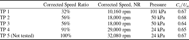
Conditions for the design of the sub-scale fan used in the present study were derived from a full-scale BLI fan design study presented in [Reference Mårtensson and Laban14]. In this target application, the fan is driven by an electric motor. The general characteristics of the sub-scale BLI fan are presented in Table 1. For the higher speed tests, the inlet pressure is sub-atmospheric in order to reduce the necessary fan power to fit the available equipment.
Design point data used for the fan

Layout of the test rig.

A CFD model is used for the unsteady aerodynamics of the BLI fan. The section of the rig modelled is shown as the URANS Domain in Fig. 1. This is a suitable domain for the evaluation of fan performance and distortion transfer through the fan including the by-pass duct. Data from the test rig are compared with results of the CFD model to ensure that the computed data are relevant. The comparisons show that the model can predict the performance of the fan in the presence of circumferential and radial distortion generated in the upstream flow field. The CFD model is then used to investigate the performance effects of distortion in more detail and variation than what is possible using the experimental data alone.
2.0 CFD Model and validation
A first computational model that is used to derive boundary conditions for unsteady computations includes the entire test rig as shown in blue in Fig. 1. This starts upstream of the centrebody and extends downstream of the fan nozzle into the exhaust pipe. Single blade sector models of the rotor and the stator represent the fan, whilst the whole 360° annulus including struts is included for the rest of the rig. The sector models are interfaced to the tunnel parts using mixing planes which enables the use of rapid steady state simulations. This model was developed to support the test campaign as described in [Reference Rasimarzabadi, Martensson, Clark and Neuteboom13]. Comparisons were made with good results to the low-speed tests. For the unsteady models, the total pressure profile can therefore be extracted at the inlet boundary of the unsteady model.
Due to the circumferential distortion elements, the sector models with mixing planes cannot be used to fully analyse the effects of propagating the distortion through the fan. For this purpose a fully transient 360° URANS model is used, including all the blades and vanes in the fan. This type of model demands orders of magnitude more computational power than sector models used for design. The modelled domain is therefore made shorter than the full length of the rig as seen in Fig. 1. By this reduction, the physical time needed for the flow to settle into a periodic state is reduced. The URANS model starts downstream of the struts, but well upstream of the inlet. This allows the flow entering the intake to re-distribute in cases of circumferential distortion. The by-pass duct and nozzle are both included in the model, which allows for the ingested flow to re-distribute ahead of the fan face and a non-uniform nozzle pressure in similarity with the rig design.
The inlet boundary condition is derived from the results of simulating the rig including the upstream struts. This is done by extracting the solution at the inlet plane to the unsteady model using an evenly distributed array of points located at 360 angles by 129 radii. The solution is then in turn interpolated to the inlet boundary and used to define the boundary conditions. The total pressure in cases with no screen is directly imposed, and in cases with a screen, it is reduced by a loss factor, $D{P_\theta }$
, applied over a sector defined by
$D{P_\theta }$
, applied over a sector defined by $\Delta \theta $
as in Equation (1), where
$\Delta \theta $
as in Equation (1), where $f\left( {r,\theta } \right)$
represents the field extracted and interpolated from the whole rig simulation.
$f\left( {r,\theta } \right)$
represents the field extracted and interpolated from the whole rig simulation.
 \begin{align}{P_{t,in}} = \left\{ {\begin{array}{*{20}{l}}{f\left( {r,\theta } \right){\rm{*}}\left( {1 - D{P_\theta }} \right){\rm{\;\;}}for{\rm{\;\;}}\theta {\rm{\;}}in:{\rm{\;\;}}180 + \Delta \theta /2 \lt \theta \lt 180 - \Delta \theta /2}\\[5pt]{f\left( {r,\theta } \right)\;\;\;otherwise{\rm{\;}}}\end{array}} \right.\end{align}
The total temperature and velocity are extracted in the same way as the total pressure, but no modifications are needed in cases with a screen. The local velocities are used to calculate the local flow directions which are imposed on the inlet boundary. Boundary conditions specified for the turbulence model utilise standard settings with a turbulence intensity ${I_t} = 5{\rm{\% }}$
and an eddy viscosity
${I_t} = 5{\rm{\% }}$
and an eddy viscosity ${\mu _t} = 50\mu $
. At the outlet boundary, only the static pressure is prescribed, which is extracted from the solution at the outlet boundary plane.
${\mu _t} = 50\mu $
. At the outlet boundary, only the static pressure is prescribed, which is extracted from the solution at the outlet boundary plane.
The unsteady computations start from a steady state solution performed on the same mesh as the one used for the unsteady computations, or in some cases a prior unsteady solution, with different distortion. From this state the simulation proceeds until a periodic state is reached. At this point the unsteady solution can be averaged to provide the data used in comparisons to test and performance evaluations.
The simulations used for the presented results are made with the k-ω SST turbulence model with a γ-θ transition model available in ANSYS CFX 2023R1. All 18 blades and 24 vanes are included in the mesh resulting in a total of 48 million grid points for the complete computational domain. Figure 2 shows a snapshot of the pressure distribution at mid-span, and the distribution of y+, which is the distance to the first grid point normalised by viscous wall scales. The transient solution was simulated over a sufficient number of revolutions until the flow was periodic. One rotation is modelled using 1,152 time steps, which means 64 time-steps per blade passage. Rotor blade sectors are modelled with about 1.3 million nodes per blade and 0.8 million nodes per vane. The transient analysis captures the blade-vane interactions as well as the circumferential distortion and how that propagates through the fan system.
View of the computational domain for URANS.

Data from the experiment was collected by traversing pneumatic probes measuring the total pressure, and by wall taps giving the static pressures at fixed positions. In some cases, when the measurements were disturbed or incomplete, not all positions are available. For such conditions, the comparison is left out. Operating the rig for extended times leads to variations in the conditions such as speed, inlet conditions and pressure ratio. All pressure data acquired were therefore normalised with the inlet total pressure at the time of measurement. The inlet total pressure denoted ${P_{t,0}}$
was measured at the nose of the centrebody in Fig. 1. Figure 3 shows pressure measurement locations and references used for the probes on the test object. As an example, the wall static pressure at the measurement point P4i is shown in Fig. 3 as
${P_{t,0}}$
was measured at the nose of the centrebody in Fig. 1. Figure 3 shows pressure measurement locations and references used for the probes on the test object. As an example, the wall static pressure at the measurement point P4i is shown in Fig. 3 as ${P_{P4i}}$
. The corresponding normalised pressure for P4i is denoted
${P_{P4i}}$
. The corresponding normalised pressure for P4i is denoted ${p_{4i}}$
and is defined as:
${p_{4i}}$
and is defined as:
 \begin{align}{p_{4i}} = \frac{{{P_{4i}}}}{{{P_{t,0}}}}\end{align}
Probe names and locations on the test object, K-blue Kiel Probe traverses, P-red Wall tap locations.

The other wall static probes marked with red diamonds are named consequently using the names indicated in Fig. 3. Data from the traversing probes are normalised in the same way. Using ${P_{t,4}}$
as the total pressure measured at the Kiel probe K4 in Fig. 3 the total pressure used for comparison to CFD is:
${P_{t,4}}$
as the total pressure measured at the Kiel probe K4 in Fig. 3 the total pressure used for comparison to CFD is:
 \begin{align}{p_{t,4}} = {{{P_{t,4}}} \over {{P_{t,0}}}}\end{align}
The normalised pressure at the hub downstream of the fan OGV, ${p_{4i}}$
, at the point P4i encircled in Fig. 3 is used to control the operating point of the fan for the comparison. During the test, the rig is controlled to a set point by targeting this ratio to reach the specified fan operating point.
${p_{4i}}$
, at the point P4i encircled in Fig. 3 is used to control the operating point of the fan for the comparison. During the test, the rig is controlled to a set point by targeting this ratio to reach the specified fan operating point.
Comparing model results for nominal tunnel.

2.1 Numerical model variation
Computational domain extent, geometric detail, numerical resolution and the choice of turbulence model may affect the results. The CFD model needs to balance computational cost with the numerical error. In order to understand the possible sensitivities and to motivate the choice of model key variations are made and tested back-to-back. The resolution is checked by comparing the reference model described above, using 64 timesteps per blade passage, to a solution using 128 timesteps per blade passage. The refined model that uses twice as many time steps per blade passage also has twice the number of nodes in the rotor and stator domains (2.6M/blade and 1.7M/vane) respectively.
Figure 4 shows a first comparison for a case running at 18,000 rpm and nominal distortion that is only due to the upstream struts and end wall boundary layers. The results are presented at the measurement locations according to Fig. 3 using contour plots and circumferentially averaged span-wise profiles of total pressure. Figure 4a and b show contour plots of total pressure normalised by inlet total pressure for the two models. In Fig. 4c diagrams for the 5 traversing stations are shown, with a red line CFD being the standard model, and the green line corresponding to the finer model marked ‘Refined’. Figure 4d shows the circumferential variation using the radial average in dots and data extracted at the mean line radius as lines. The differences are very small between the simulations.
The same two models are used to compare a case with a larger circumferential variation using a distortion screen covering a 90° sector. Figure 5a–d shows the comparison done with a screen as depicted in Fig. 1 causing a pressure loss of 3% of the inlet total pressure.
Comparing model results for distortion with screen.

No discernible difference is visible comparing the contour plots in Fig. 5a and 5b, showing that there are no significant local differences in the analyses. Overlaying plots of the radial variation of circumferentially averaged total pressure gives a view pertinent to the radial distortion evolution and the lines for the analyses are almost identical, with the red line hidden behind the green almost everywhere. In Fig. 5d the circumferential variations are shown at the fan inlet and downstream the OGV. As reference, total pressure the mid span total pressure at K1 between wakes is used. The variation of total pressure at the mid span radius is plotted as full lines. In addition, the radial average of total pressures is computed and plotted as dotted lines using the same reference. No differences are visible at plane K2. At plane K4, downstream of the fan, the lines are visibly separated in a region around –120°, but the differences are still very small in comparison to the variations due to distortion that the computations aim to capture. As no significant differences are found the coarser CFD model is found adequate and is used in the studies below.
2.2 Validation of the URANS calculation with test
A selection of operating points is listed in Table 2. These are used for analyses and validation for low to high speeds and at different load points. In addition to varying operating points with a nominal tunnel, test data is used from tests with a distortion screen over a 90° sector. These tests are carried out to provide a stronger circumferential distortion, which allows for a data set focused on the transfer of circumferential distortion.
Nominal operating points
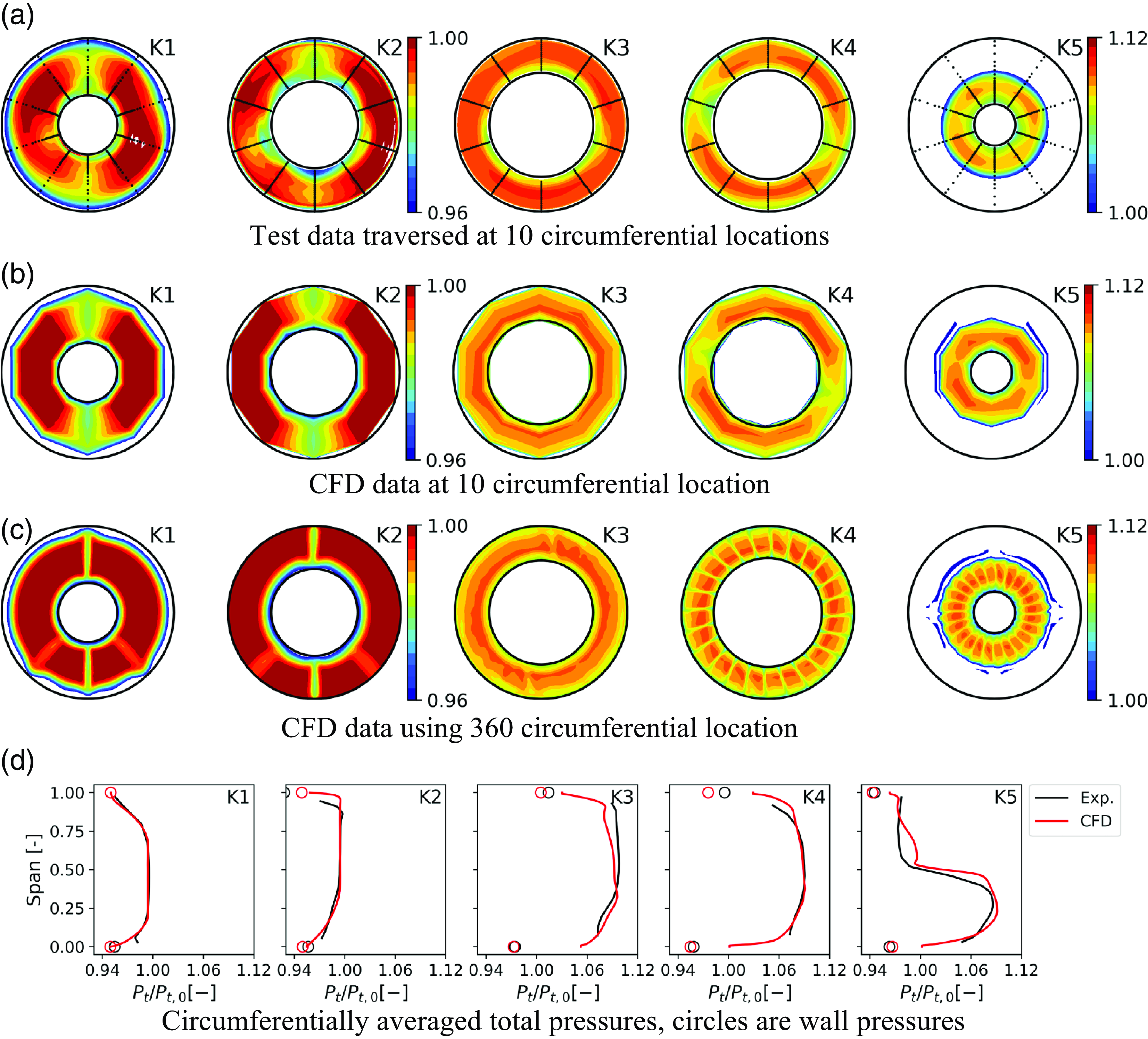
TP 2 Comparison of CFD to test data at medium speed and 50 kPa.
The low-speed data TP 1 was collected using a bell mouth at the inlet providing atmospheric conditions in the test section and a clean inflow condition. A comparison to CFD using a sector model at this condition was shown in [Reference Rasimarzabadi, Martensson, Clark and Neuteboom13], where the measurement strategies were in focus, with a good correlation.
A similar comparison made at TP2 (18,000 rpm/50 kPa) is shown in Fig. 6. Generally the correlation is good but reveals some features in the traverse data not observed in the CFD data. Closer to the inner wall the K2 profile in Fig. 6d departs from the expected behaviour in the boundary layer. At the outer wall, the profile drops earlier and exhibits a small overshoot at K2 that is not seen in the CFD. At K3 the total pressure rise in the experiment exceeds the CFD slightly over the outer part of the span. Static wall pressures match well with the CFD result at the inner wall and exhibit more variation at the outer wall of the fan flow path. Downstream of the OGV, the total pressure profile is in good agreement over most of the span, away from the walls. Figure 6a shows the total pressure variation at the 10 circumferential locations. The overlaid dots mark measurement locations in the test. In Fig. 6b data are shown as a polygon in the CFD to highlight the effects of resolution on the traverses that are used in the comparison. In the CFD it is done by picking out the same 10 circumferential positions for the plots as those measured. The pattern exhibits the low total pressure regions seen in the measurement at K4, downstream of the OGV in this view. In the CFD model, the resolution is much higher exhibiting all the stator wakes, and this can be seen in Fig. 6c where the plots include data extracted with a resolution of 1° or less circumferentially. This demonstrates that the circumferential variation apparent in the K4 position in the measurement is due to the alignment of the traverse probe with the wakes from the OGV. Note that the white patches represent data exceeding the colour scale on either end.
A second test at the TP2 conditions was performed measuring with higher resolution over a 30° sector, corresponding to two OGV passages with a step of 2°. The data in Fig. 7a is shown for this sector with dots marking the individual points of measurement. K1–K3 were measured simultaneously whereas planes K4 and K5 were individually traversed with the upstream traverse probes retracted. During K1-K3 traverses the fan motor speed made a slight overshoot which is seen in the slight but abrupt shift observed in the traverses. The features observed in test and CFD, Fig 7b, are however similar. Altogether the correlation is reasonable.
TP2 Comparison of CFD to experiment over a 30° sector.

Increasing the pressure in the duct downstream of the fan leads to an increase in fan pressure ratio but also to a reduction in by-pass flow. A lower velocity in the upstream duct results from this which reduces the boundary layer momentum deficit at the walls along the centrebody and lowers the strut wake strength as seen in Fig. 8c. The comparison in Fig. 8a and 8b shows similar differences to Fig. 6a and 6b between CFD and the experiment where the pressure rise is increased. Generally, at this operating condition, the experimental pressure profiles are observed to be slightly lower relative to CFD at all stations, including the stations upstream of the fan.
TP3 Comparison of CFD with experimental data at medium speed and increased back pressure.

TP4 Comparison of CFD to test data at high speed.

The highest rig speed that allowed running for sufficient time to collect traversing data was the case TP4 at 29,000 rpm, with results shown in Fig. 9a–c. This is 91% of the fan design speed, and the blades operate with a substantial part of the suction side in supersonic conditions. Some differences between measurement and CFD can be observed toward the end walls. At station K2 in Fig. 9c there is a cusp near the outer wall in the measurement that is not present in the CFD. There is no aerodynamic reason for this to occur, that would not be seen also at station K1, and it is likely to be due to the low rig pressure used at this test condition. At station K3 a difference is observed showing a lower pressure at low span downstream of the rotor. This difference is not believed to be due to unpredicted losses incurred in the rotor, also here a problem with the K3 measurement at the low pressure. Comparing with the measured profile at station K4 the total pressure at lower span is higher than for the same span at the upstream location K3, which is not physically reasonable. Figure 8c shows some similarities with respect to these features, but they are much less pronounced as the rig pressure is higher in the TP3 case.
An important purpose of the comparison to experimental data is to confirm that the transfer of circumferential distortion can be predicted with the CFD model. The operating point at TP3 is therefore revisited with the addition of a distortion screen covering a 90° sector mounted at the noses of the struts at the location indicated in Fig. 1. Figure 10a shows the measurement of the same 10 circumferential locations as before where the reduced total pressure can be observed at the bottom traverses. This is complemented by a second test shown in Fig. 10b where a few radii are measured but 90 circumferential positions are used at 4° intervals. The dots indicate the locations of the data points in this test. The extent of the screen can be seen as well as the traces of the distorted sector as it propagates through the fan. More of the wakes from the OGV become visible, but since there are still few points per vane passage in the circumferential direction so some wakes appear to be missing in the plot. Figure 10c shows the distorted sector from CFD in higher resolution as before. In the CFD the screen was modelled by adding an assumed pressure loss of 3% of the total pressure over an exact 90° degree sector. The transfer through the fan shows a similar rotation of the pattern in CFD as in the test. Considering the radial profiles in Fig. 10d the K2 shows a peculiar linear increase from hub to shroud that has not been seen before, which could be an artefact of the averaging.
TP2 Comparison of CFD with experimental data with distortion screen.

The circumferential variation of total pressure at the mid span is extracted and compared to the CFD results. In Fig. 11a results are compared for the case with a nominal tunnel, without screen. The comparison is made using the K1 data as the upstream starting point. Two tests are used to evaluate the circumferential distortion transfer and the capability of predicting this in CFD. Figure 11b shows results from the medium speed case TP2 for a back-to-back comparison of the effect of adding the distortion screen with the nominal case. It is immediately clear comparing the experimental results that the screen has a significant and measurable effect on the total pressure distribution. In both cases, CFD results are overlaid to show the difference in the model. The circumferential total pressure distribution can be followed from the K1 to the K4 location. Despite the difference in inlet profiles, it is clear that the circumferential distortion transfer can be predicted in the CFD model.
TP2 Comparison to CFD of transfer of the circumferential pattern.

2.3 Performance metrics
Fan performance and distortion transfer can be evaluated using the rig context, but further steps are needed to evaluate the efficiency of the installed propulsion system. In general, by integrating the fan more closely with the fuselage the drag could be affected as well as the thrust generated by the flow through the fan. In order to focus on the propulsor and fan performance in distortion, the metrics used here will only consider the flow passing through the fan.
The fan isentropic efficiency is calculated using mass flow averaged quantities. The mass flow average of a variable $\phi $
over a plane K in the fan flow path is defined by:
$\phi $
over a plane K in the fan flow path is defined by:
 \begin{align}{\tilde \phi _K} = \frac{{\;\mathop \smallint \nolimits_K \rho u\phi \left( {y,z} \right)dydz}}{{\dot m}}\end{align}
The total pressure ratio over the fan stage is then:
 \begin{align}PR = \frac{{{{\tilde P}_{t,4}}}}{{{{\tilde P}_{t,2}}}}\end{align}
The fan efficiency is defined as the ratio of the power needed to obtain the pressure ratio PR with an isentropic process to the actual power to the fan:
 \begin{align}\eta = \left( {P{R^{\frac{{\gamma - 1}}{\gamma }}} - 1} \right)\bigg/\left( {\frac{{{{\tilde T}_{t,4}}}}{{{{\tilde T}_{t,2}}}} - 1} \right)\end{align}
The overall efficiency of the propulsion system can be stated in terms of the power consumed by the fan to generate thrust by increasing the momentum of the flow. A simple BLI system sketch that is needed to define the performance metrics is shown in Fig. 12.
Sketch of stations used for net thrust calculation.

The ability to generate thrust will be evaluated using two separate metrics. The first is based on station averages similar to a compression system metric using mass flow averaged total quantities. This gives a simple and well-defined way of calculating the net thrust that will be identified as ‘1D’ metrics. The 1D net thrust can be calculated as in Equation (7) using station data considering ${\tilde P_{t,2}}$
as the inlet total pressure and using the free stream static pressure in the calculation of the velocity
${\tilde P_{t,2}}$
as the inlet total pressure and using the free stream static pressure in the calculation of the velocity ${V_e}$
in Fig. 12.
${V_e}$
in Fig. 12.
 \begin{align}{F_{N,1D}} = \dot m\left( {{V_{j,1D}} - {V_{e,1D}}} \right)\end{align}
Calculating the velocities as ${V_{1D}} = f\left( {{{\tilde T}_t},{{\tilde P}_t},{P_{inf}}} \right)$
is done using the standard 1D compressible flow formulae. This neglects the effects that the fan may have on the fuselage drag but gives a metric that is straightforward to work with for evaluating a fan design and test or analysis result.
${V_{1D}} = f\left( {{{\tilde T}_t},{{\tilde P}_t},{P_{inf}}} \right)$
is done using the standard 1D compressible flow formulae. This neglects the effects that the fan may have on the fuselage drag but gives a metric that is straightforward to work with for evaluating a fan design and test or analysis result.
For the larger scale non-uniformity entering the fan, the total pressure deficit persists through the machine and beyond the nozzle exit. An example of this can be seen in Fig. 5 where the sector of low total pressure due to the ingested distortion at plane K4 remains downstream of the nozzle at plane K5. The thrust was calculated using Equation (7) does not consider a variation of this kind. A second metric is therefore introduced that does not average the total quantities but rather treats each infinitesimal stream tube independently of the other stream tubes. Each stream tube contributes thrust as in an ideal model of a fan. This neglects mixing between stream tubes in the jet but has merit in providing a view of what the effects of transferring the non-uniformity due to distortion can be. The net thrust calculation in Equation (8) is made using an integral of the thrust for each infinitesimal stream tube instead of using the mass averaged total pressure at the stations. Using this metric still however does not model effects on the external aerodynamics. For the net thrust we thus have:
 \begin{align}{\tilde F_N} = \mathop \smallint \nolimits_{K4} \rho uVdydz - \mathop \smallint \nolimits_{K2} \rho uVdydz\end{align}
Where $V = f\left( {{T_t},{P_t},{P_{inf}}} \right)$
is based on local variables and the free stream pressure.
$V = f\left( {{T_t},{P_t},{P_{inf}}} \right)$
is based on local variables and the free stream pressure. ${\tilde F_N}$
is equivalent to the 1D form
${\tilde F_N}$
is equivalent to the 1D form ${F_{N,1D}}$
for constant flow properties over the inlet and outlet from the fan. In the case of BLI, the effective velocity at the entry is lower as the total pressure is reduced due to drag. For an ideal gas simulation, the power added to the flow can be calculated from the rise of total temperature in the CFD model:
${F_{N,1D}}$
for constant flow properties over the inlet and outlet from the fan. In the case of BLI, the effective velocity at the entry is lower as the total pressure is reduced due to drag. For an ideal gas simulation, the power added to the flow can be calculated from the rise of total temperature in the CFD model:
 \begin{align}E = \dot m{c_p}\left( {{{\tilde T}_{t,4}} - {{\tilde T}_{t,2}}} \right)\end{align}
An overall efficiency can be defined as a power coefficient, $CP$
, to describe the BLI fan propulsor. The power coefficient is the power contributed to the aircraft propulsion by the thrust divided by the power added to the flow by the fan.
$CP$
, to describe the BLI fan propulsor. The power coefficient is the power contributed to the aircraft propulsion by the thrust divided by the power added to the flow by the fan.
 \begin{align}CP = \frac{{{V_{inf}}{F_N}}}{E}\end{align}
It should be noted that by the definition of E this includes the efficiency of the fan in the power added to the flow.
3.0 Performance with distortion
Fan performance is evaluated in several cases with ingested distortion. Computations are made at two speeds and evaluated in some more detail relevant to performance. The CFD model used is the same as the above validated model. Normalised speed, distortion level and the extent of circumferential distortion are relevant parameters covered by the computations. The design of the test object was made for mainly radial distortion, based on the computed inlet flow obtained from a whole aircraft model. The blade and vane profile design can be adapted to the radial variation, but the circumferential distortion has an impact on the performance that is not explicitly considered in the design. A common way of defining the circumferential distortion level is to use a distortion index normalised the dynamic pressure in front of the fan rotor. A common such index is $DC60$
defined in Equation (11).
$DC60$
defined in Equation (11).
 \begin{align}DC60 = \frac{{{{\tilde P}_{t,2}} - {{\tilde P}_{t60,min}}}}{{{{\tilde P}_{t,2}} - {{\bar P}_2}}}\end{align}
where ${\tilde P_{t60,min}}$
denotes the 60º degree sector with the lowest average total pressure.
${\tilde P_{t60,min}}$
denotes the 60º degree sector with the lowest average total pressure.
For the tail mounted BLI fan in [Reference Mårtensson and Laban14] the total pressure variation is predominantly radial and the DC60 distortion index was 12% at the aircraft design point. Higher levels of distortion can be expected depending on the installation and mode of operation of the aircraft, so it is of great interest to study higher levels of circumferential distortion. By comparison, data are presented in [Reference Hall, Greitzer, Uranga, Drela and Pandya15] from wind tunnel tests of a BLI configuration aircraft D8 with fans mounted on the upper fuselage. The DC60 index levels reported are in the interval of 39%-44% at cruise up to the highest reported value of 62%.
The rig tests provide data on the fan in distorted inlet flow, but it does not provide a total pressure loss up to the intake that is relevant for an actual aircraft. A notional case is therefore derived from the study in [Reference Mårtensson and Laban14]. This is combined with data from the sub-scale fan in this study and used as a reference to the effects of varying distortion. A reference point is then established using computed data for low distortion in the rig. The reference fan operating condition performance is stated in Table 1 as TP5 at a pressure ratio $PR = 1.3\;$
and an isentropic efficiency of 84% in the CFD model with a nominal tunnel.
$PR = 1.3\;$
and an isentropic efficiency of 84% in the CFD model with a nominal tunnel.
The design point Mach number of the aircraft in [Reference Mårtensson and Laban14] was ${M_{inf}} = 0.74,$
which gives a free stream total pressure,
${M_{inf}} = 0.74,$
which gives a free stream total pressure, ${P_{t,inf}} = 1.44*{P_{s,inf}}$
. A fan with the reference performance operated with a clean inflow at free stream conditions gives a
${P_{t,inf}} = 1.44*{P_{s,inf}}$
. A fan with the reference performance operated with a clean inflow at free stream conditions gives a $CP = 0.74$
. Used as a BLI fan the mass averaged total pressure at the fan inlet in [Reference Mårtensson and Laban14] was reduced to 86% of the freestream value which gives
$CP = 0.74$
. Used as a BLI fan the mass averaged total pressure at the fan inlet in [Reference Mårtensson and Laban14] was reduced to 86% of the freestream value which gives ${P_{t,2}} = 1.24*{P_{s,inf}}$
. Using this value of
${P_{t,2}} = 1.24*{P_{s,inf}}$
. Using this value of ${P_{t,2}}$
results in
${P_{t,2}}$
results in $CP = 0.88$
, which suggests a significant improvement over the free stream, clean inlet case. It should, however, be kept in mind that the
$CP = 0.88$
, which suggests a significant improvement over the free stream, clean inlet case. It should, however, be kept in mind that the $CP$
definition considers the fan in isolation with specified BLI distortion. Accounting for effects on the whole aircraft, and by that the power needed for propulsion, requires an integrated model. In a case with a gas turbine powering the fan, the effects of distortion on the core efficiency will also need to be addressed. The reference BLI system in the study aims to provide only a smaller part of the total thrust at the design point, which allows the fan to capture a stream of lower mean total pressure than if all the thrust was provided by the BLI fan. The effectiveness of the fan in the BLI application depends on both the reduction of the total pressure of the ingested flow and the effect of the distortion on the fan efficiency. When operating the fan in conditions with distortion it may be anticipated that the performance of the fan will be adversely affected. The effects of ingesting distorted flow can be studied by application of a loss over a sector as shown in Fig. 10 for the distortion screen. Using the context of the test rig has the advantage that the model can be used with some confidence that the results are valid. A sequence of screen sector sizes and losses are simulated using the URANS model.
$CP$
definition considers the fan in isolation with specified BLI distortion. Accounting for effects on the whole aircraft, and by that the power needed for propulsion, requires an integrated model. In a case with a gas turbine powering the fan, the effects of distortion on the core efficiency will also need to be addressed. The reference BLI system in the study aims to provide only a smaller part of the total thrust at the design point, which allows the fan to capture a stream of lower mean total pressure than if all the thrust was provided by the BLI fan. The effectiveness of the fan in the BLI application depends on both the reduction of the total pressure of the ingested flow and the effect of the distortion on the fan efficiency. When operating the fan in conditions with distortion it may be anticipated that the performance of the fan will be adversely affected. The effects of ingesting distorted flow can be studied by application of a loss over a sector as shown in Fig. 10 for the distortion screen. Using the context of the test rig has the advantage that the model can be used with some confidence that the results are valid. A sequence of screen sector sizes and losses are simulated using the URANS model.
The first cases are set up by varying the distorted sector size from 0° to 120°. This is done whilst keeping the pressure drop over the screen ${\rm{\;}}D{P_\theta } = {\rm{\Delta }}{P_t}/{P_{t,0}} = 3\% $
. A modest decrement of the fan efficiency is found, <0.4%, as shown in Fig. 13a. The flow coefficient was reduced by ∼1% and the pressure rise increased by a very small amount as shown in Fig. 13b.
${\rm{\;}}D{P_\theta } = {\rm{\Delta }}{P_t}/{P_{t,0}} = 3\% $
. A modest decrement of the fan efficiency is found, <0.4%, as shown in Fig. 13a. The flow coefficient was reduced by ∼1% and the pressure rise increased by a very small amount as shown in Fig. 13b.
Effect of increasing screen sector size at 18,000 rpm.

For two cases corresponding to TP2 and TP5, the variation of efficiency with distortion level is made for a 90° sector. Figure 14 shows the effect of increasing screen loss, giving an increasing distortion level. The maximum pressure screen loss used is the last that could be computed with respect to the bypass flow. At the higher speed, a larger screen pressure drop could be simulated before the flow in the bypass started to significantly back up in the zone of low total pressure ahead of the fan. For the screen with the highest pressure drop the efficiency is reduced by ∼2% in both cases. The overall efficiency is shown in terms of the power coefficient CP from Equation (10) at 32,080 rpm where the Mach number for the notional aircraft was known. The chart in Fig. 14b shows two lines corresponding to different ways of calculating the power coefficient. Mass flow averaged variables are used to calculate thrust for the 1D measure according to Equation (7) is shown as the dashed line. The thrust calculation is based on the summation of each stream tube individually as in Equation (8), is shown as a solid line. At lower distortion levels the difference is very small but increases at the higher distortion, where the 1D model drops off more rapidly following the fan efficiency. The difference between the measures lies in the weighting of the variation. The transfer of the distortion field will lead to change or attenuation of the distortion field as the rotor tends to do more work on the stream tubes in the low-pressure sector, thus creating a difference compared to the 1D metric.
Effect of increasing screen loss ( ${\rm{D}}{{\rm{P}}_{\rm{\theta }}})$
applied over a 90° sector.
${\rm{D}}{{\rm{P}}_{\rm{\theta }}})$
applied over a 90° sector.

Figure 15a gives an overview of the changes to the distortion field through the fan in the case of fan 32,080 rpm and screen pressure loss of 9%, encircled in blue in Fig. 14. The low static pressure forming ahead of the fan is visible at plane K2 and drops through the fan with a slight asymmetry still visible at K4. The total pressure field rotates slightly through the fan, consistent with earlier findings and tests. The axial velocity plots show that there is still a significant axial velocity in front of the fan at K2 despite the lower total pressure in the distorted sector. Both at the entry, K2, and the exit, K4, significant variations remain in both total pressure and the axial velocity can give rise to the difference in the net thrust calculation. We can have one measure of attenuation by comparing the change to DC60 criterion through the fan. Calculating the DC60 criterion this case shows that this criterion is reduced from 48% at K2 to 24% at K4, which is a reduction of 50%. Figure 15b shows the local work coefficient at plane K4, which shows where work has been added to the flow on the passage through the fan.
Transfer of the distortion field through the fan at TP5 (32,080 rpm) and a screen pressure loss, ${\rm{D}}{{\rm{P}}_{\rm{\theta }}} = 9{\rm{\% }}$
, applied over a 90° sector.
${\rm{D}}{{\rm{P}}_{\rm{\theta }}} = 9{\rm{\% }}$
, applied over a 90° sector.

The effects of pressure drop on the fan efficiency appear stronger for the lower speed. Using a distortion index that is based on the dynamic pressure goes some way in explaining differences. In Fig. 16a the $DC60$
index is plotted as a function of the screen pressure drop for the two speeds. The highest computed
$DC60$
index is plotted as a function of the screen pressure drop for the two speeds. The highest computed $DC60$
is over
$DC60$
is over $90\% $
at the lower speed, which leads to a very substantial static pressure reduction in front of the fan. The vector plot in Fig. 16b overlaid on the static pressure distribution shows how flow is preferentially drawn into the distorted sector of the fan. This has been shown and discussed in for instance [Reference Gunn and Hall10] and helps sustain the axial velocity entering the fan in the distorted sector. In this rig, the fan can also ingest flow from the stream that would otherwise pass through the by-pass. Figure 16b shows the static pressure on the K1 plane with velocity vectors for the encircled point. The vectors show the radial re-distribution of the flow in addition to the circumferential. The ring of high static pressure is due to the stagnation of the flow approaching the intake lip.
$90\% $
at the lower speed, which leads to a very substantial static pressure reduction in front of the fan. The vector plot in Fig. 16b overlaid on the static pressure distribution shows how flow is preferentially drawn into the distorted sector of the fan. This has been shown and discussed in for instance [Reference Gunn and Hall10] and helps sustain the axial velocity entering the fan in the distorted sector. In this rig, the fan can also ingest flow from the stream that would otherwise pass through the by-pass. Figure 16b shows the static pressure on the K1 plane with velocity vectors for the encircled point. The vectors show the radial re-distribution of the flow in addition to the circumferential. The ring of high static pressure is due to the stagnation of the flow approaching the intake lip.
Dynamic distortion index and flow pattern ahead of fan.

4.0 Conclusion
The complex aerodynamics of a boundary layer ingesting fan in a test rig with a bypass stream has been modelled with CFD. Comparisons are made for different speeds as well as for increased circumferential distortion. This shows satisfactory results compared to the experiments. The model has then been used to undertake parametric studies and gain more insight into the performance of the BLI fan.
The potential benefit in overall efficiency due to BLI stems essentially from the average pressure loss up to the fan inlet. A circumferential distortion of the ingested flow affects the fan efficiency adversely. At the higher circumferential distortion levels, it is found that the accounting of the net thrust will be important as the mixing processes of the flow are not complete at the inlet and nozzle. The change across the fan as the ingested distortion is attenuated may, therefore, have a significant impact on the net thrust. The effect of adding circumferential distortion is detrimental to fan efficiency but the benefits outweigh the loss of fan efficiency in the studied application.
There are nevertheless remaining issues linked to the distortion. Here the main distortion parameter is the total pressure variation, strong vorticity or other detrimental flow patterns could prove to be more severe to the efficiency. Other pertinent issues are operability in terms of stall margin when the fan is highly loaded, as well as noise and blade vibrations.
Acknowledgments
GKN Aerospace Engines AB and the National Research Council of Canada for granting permission to publish this work. NFFP, the Swedish National Aeronautical Research Program for funding parts of this work.
Competing interests
The author(s) declare none.


 Open access