


Nomenclature
Symbols
- A f
-
austenite finish temperature (°C)
- A s
-
austenite start temperature (°C)
- M f
-
martensite finish temperature (°C)
- M s
-
martensite start temperature (°C)
- δ
-
displacement (mm)
- f
-
spring force (N)
- k
-
spring stiffness (N/mm)
- d
-
wire diameter of spring (mm)
- D
-
coil diameter of spring (mm)
- N
-
number of active coils (–)
- G
-
shear modulus (GPa)
- T
-
temperature (°C or K)
- m
-
mass (kg)
- C p
-
specific heat capacity (J/kg·K)
- L
-
latent heat of transformation (J/kg)
- ξ
-
martensite volume fraction (–)
- h
-
heat transfer coefficient (W/m2·K)
- A
-
surface area of SMA spring (m²)
Abbreviations
- SMA
-
shape memory alloy
- SME
-
shape memory effect
- PE
-
pseudo-elasticity
- NiTi
-
nickel-titanium alloy
- UAV
-
unmanned aerial vehicle
- AM
-
additive manufacturing
- L-PBF
-
laser powder bed fusion
- PLA
-
polylactic acid (3D printing filament)
- PETG
-
polyethylene terephthalate glycol (3D printing filament)
- FDM
-
fused deposition modeling
- CAD
-
computer-aided design
- DOF
-
degree of freedom
1.0 Introduction
Shape memory alloys (SMAs) are functional materials with distinctive features like the shape memory effect (SME) and pseudo-elasticity (PE), making them ideal for aerospace, biomedical engineering and robotics applications [Reference Mohd Jani, Leary, Subic and Gibson1]. Nickel-titanium (NiTi) alloys are the most common SMAs due to their excellent biocompatibility, high energy density and superior fatigue resistance features [Reference Wadood2]. These materials can recover significant deformations after heating (SME) or unloading (PE), which allows their use in actuators, dampers and other smart systems [Reference Costanza and Tata3].
The unique properties of SMAs originate from a reversible, thermoelastic martensitic phase transformation between a high-symmetry (austenite) and a low-symmetry (martensite) crystal structure. At low temperatures, the alloy is in the easily deformable martensitic phase. When heated above its transformation temperature, it reverts to the stiffer austenitic phase, recovering its original shape. This process exhibits thermal hysteresis, a critical factor in actuator design, with a typical width of 27.8 to 67.8 °C [Reference Lagoudas4, Reference Otsuka and Ren5]. In recent decades, several constitutive models have been developed to characterise the thermo-mechanical characteristics of the NiTi alloy, significantly facilitating its widespread application in engineering as an SMA [Reference Yu, Kang, Song and Kan6]. The two primary characteristics of SMAs are the SME and pseudo-elasticity. The SME allows a deformed material to return to its predetermined shape upon heating, which is useful for applications in various fields including aerospace. The material is first loaded and then unloaded, leaving a residual strain; subsequent heating eliminates this strain and restores the original shape. This effect can be one-way, where the material only remembers its high-temperature shape, or two-way, where it remembers both low- and high-temperature shapes through thermomechanical training.
The other key characteristic is pseudo-elasticity, which occurs at a constant temperature above the austenite finish point (A f). The material can endure large deformations during loading and then instantly return to its original shape upon unloading. This complete strain recovery, which traces a characteristic hysteresis loop, is a critical behaviour for applications needing high elasticity without thermal cycling [Reference Tanaka, Himuro, Kainuma, Sutou, Omori and Ishida7].
SMA technology is a mature and commercially significant field with thousands of patents, widely applied in industries like aerospace and automotive by leading corporations [Reference Tanaka, Himuro, Kainuma, Sutou, Omori and Ishida7, Reference Mammano and Dragoni8]. For instance, Boeing, in partnership with NASA, has successfully developed and flight-tested a Variable Geometry Chevron (VGC) system using high-temperature SMAs, demonstrating its potential to reduce noise and improve cruise efficiency on future aircraft [Reference Ahmad, Hashmi, Iqbal, Rab and Tian9]. NASA employs SMA technology for critical space missions, such as in low-shock release mechanisms for solar panels and micro-vibration isolators [10]. In the automotive sector, General Motors has utilised the technology in applications like the trunk venting mechanism in the Chevrolet Corvette [11]. Furthermore, the Defense Advanced Research Projects Agency (DARPA) has pioneered military applications, including CryoFit hydraulic pipe fittings on the F-14 aircraft and the ‘Smart Wing’ initiative for the F-15. These high-profile examples underscore the importance of SMA technology and motivate further research into novel applications like the one proposed in this study [Reference Balasubramanian, Srimath, Vignesh and Rajesh12].
An SMA actuator typically consists of an SMA element working against a counter-element like a spring. At low temperatures, the counter-element deforms the flexible SMA element. Heating the SMA element above its transition temperature increases its stiffness, allowing it to overcome the counter-element, producing displacement and mechanical work [Reference Mammano and Dragoni8, Reference Mertmann and Vergani13]. This thermal activation can be achieved through Joule heating or ambient temperature changes, enabling compact actuation solutions [Reference Mohd Jani, Leary, Subic and Gibson1]. Due to their ability to recover shape under high loads and their high actuation energy densities, SMAs are often preferred over other active materials for applications requiring high force and displacement at low to medium frequencies [Reference Huang, Leary, Ataalla, Probst and Subic14]. SMAs are available in various forms, such as wires, rods and springs. Helical SMA springs are particularly useful in aerospace as they provide large strokes and forces in compact spaces. The chosen form directly impacts key actuation parameters like stroke length, speed and efficiency [Reference Mohd Jani, Leary, Subic and Gibson1, Reference Ma, Karaman and Lagoudas15].
Recent advances in additive manufacturing (AM), such as laser powder bed fusion (L-PBF), have expanded the potential of SMAs by enabling the fabrication of complex geometries with customised mechanical properties for aerospace designs [Reference Khanlari16]. However, controlling phase transformation temperatures and ensuring consistent material properties remain key research challenges [Reference Zhu17].
In aerospace applications, SMAs are highly advantageous for their lightweight, compact and reliable nature. They have been used in deployable structures, vibration-damping systems and morphing wing technologies [Reference Biasutti18, Reference Barakat19]. The high force-to-weight ratio of SMA springs makes them a promising candidate for demanding applications such as landing gear door lock mechanisms, offering the potential to simplify design and enhance performance [Reference Ikuta20, Reference Follador, Cianchetti, Arienti and Laschi21]. Traditional landing gear systems often depend on heavy, complex and failure-prone hydraulic or mechanical components, which increase maintenance costs and reduce system reliability [Reference Deng, Ompusunggu, Xu, Skote and Zhao22]. In contrast, SMA-based systems provide a passive or semi-active alternative with fewer moving parts and lower maintenance needs, which is a critical advantage for platforms with strict volume and weight limits, like unmanned aerial vehicles (UAVs) [Reference Nespoli23, Reference Kubasova24].
1.1 Selection methodology and literature evaluation
Before the conceptual design phase, an extensive literature review was conducted to identify existing mechanisms that either incorporate SMA actuation or exhibit clear potential for SMA integration, including retention, latching, release and locking mechanisms, with particular emphasis on those tailored for aerospace environments. The objective was to evaluate systems compatible with the high energy density and compact nature of SMA actuation. Through a systematic review of academic publications, technical reports and patent databases, a total of 42 mechanisms were initially identified.
These mechanisms were subsequently screened and reduced to 12 candidate concepts based on their activation duration, simplicity and suitability for aviation applications. A structured multi-criteria evaluation methodology was then applied, in which the shortlisted mechanisms were systematically assessed according to criteria including applicability to aviation systems, mechanical simplicity, actuation approach, activation response time, suitability for operation within confined spaces, compatibility with SMA-based actuation and operational lifespan.
Based on the outcomes of this evaluation, the conceptual design of the landing gear hook lock mechanism was developed by synthesising the advantageous features of the highest-ranked mechanism with an integrated secondary safety locking function.
Historically, SMA aerospace applications have centred on morphing surfaces, vibration attenuation and release devices [Reference Costanza and Tata3, Reference Hartl and Lagoudas25]. Key breakthroughs include actuators for noise reduction [Reference Calkins, Mabe and Butler26], optimal configurations for flap control [Reference Leal and Savi27] and reduced UAV architectures using monolithic components [Reference Ameduri, Concilio, Favaloro and Pellone28]. Research also suggests SMA utility in landing systems for airships [Reference Dayananda, Subrahmanya, Senthil and Ramaswamy29] and rotorcraft [Reference Magesh and Jawahar30], seeking enhanced energy dissipation and ground contact stability.
While these developments emphasise the value of SMAs, most contemporary systems prioritise single-mode actuation or damping [Reference Rodino and Maletta31, Reference Sohn, Ruth, Yuk and Choi32]. The suggested technique introduces dual-functionality by integrating active Joule-heated unlocking with a passive, spring-driven self-locking condition that requires no energy during cruise. Such non-pyrotechnic techniques are also validated in high-load spacecraft release duties [Reference Smith and Garman33], with a comparison presented in Table 1.
Comparative analysis of SMA-based actuators and mechanisms in aerospace

Table 1 Long description
The table compares various shape memory alloy-based actuators and mechanisms in aerospace applications. It includes five rows and five columns. The columns are labeled System/project, Actuation principle, Primary application, Key features, and Performance metrics. The rows detail different systems such as NASA release mechanism, Boeing VGC, CIRA UAV actuator, Starsys Qwknut, and Proposed SMA-based hook-lock mechanism. Each row lists the actuation principle, primary application, key features, and performance metrics for each system. For example, the NASA release mechanism uses low-shock SMA for payload deployment with shock-free, low-vibration features and high precision release performance. The Boeing VGC uses controlled 60-nitinol for engine chevrons with noise and thrust optimization and is flight-tested at cruise. The CIRA UAV actuator uses SMA wire bundle for small UAV control with system simplification and high force transmission. The Starsys Qwknut uses SMA actuator for spacecraft release with fast, non-pyro, resettable features and up to 13.3 kilonewtons capacity. The proposed SMA-based hook-lock mechanism uses NiTi spring for UAV door hook lock with integrated active unlock and passive self-lock features and 34 newtons force, 7 millimeters stroke.
In this study, we propose a novel SMA-based actuation and self-locking mechanism for aircraft landing gear doors. The mechanism uses the SME of NiTi springs for reliable, lightweight door actuation, removing the need for conventional hydraulic or electromechanical systems. This work builds on previous research by focusing on tuning the spring design and thermal activation for better performance. This mechanism’s originality is attributed to its innovative application of an SMA actuator in a dual-function design for a UAV landing gear door lock.
It notably integrates active unlocking, initiated by the electrical heating of the SMA spring, with a passive self-locking mechanism facilitated by preloaded tension springs. This integrated system guarantees secure lock maintenance without constant power, providing a lightweight, compact and structurally simple alternative to the complex and heavy hydraulic or electromechanical systems commonly employed in aerospace.
2.0 Design concept of the SMA-actuated mechanism
The suggested mechanism functions through the one-way shape memory effect demonstrated by a NiTi-based SMA, which experiences a reversible phase transformation when subjected to heat stimuli. The unlocking mechanism is facilitated by engaging the SMA actuator through resistive (Joule) heating, while the device autonomously re-locks via a preloaded tension spring. The self-locking feature guarantees secure engagement without necessitating ongoing power usage. Figure 1 illustrates the overall perspective of the designed mechanism.
Overall view of the landing gear compartment with integrated lock mechanism.

Figure 1 Long description
The illustration depicts a detailed view of a landing gear compartment featuring an integrated lock mechanism. The compartment is shown with various structural components, including beams, supports, and mechanical parts. The lock mechanism is centrally positioned, with visible gears and levers indicating its functionality. The overall design suggests a complex system intended for secure and efficient operation.
Comprehensive moment and stroke evaluations were undertaken through kinematic and dynamic analysis to establish the optimal configuration of the system components and to minimise energy consumption. By utilising the thermomechanical features of NiTi-based SMAs, a compact actuation mechanism with a simplified and lightweight architecture was developed. The dimensions of the mechanism are given in Fig. 2.
Technical drawing of the landing gear door lock mechanism.

Figure 2 Long description
The image presents a technical drawing of a landing gear door lock mechanism. The front view shows a detailed assembly with a spring, various bolts, and a coiled component. The left view provides a side perspective of the mechanism, highlighting its dimensions and structural features. The drawing includes precise measurements and annotations to indicate the placement and function of each part.
The design of the SMA-driven hook lock mechanism for UAV landing gear doors was developed based on several key principles. NiTi-based SMA actuators were adopted due to their high energy density and stable actuation performance, while a self-locking functionality was integrated to ensure secure engagement without continuous power consumption. A Joule heating-based activation technique was employed to provide precise and efficient thermal control of the SMA components. To further enhance reliability, a secondary safety lock was incorporated to prevent unintentional activations resulting from potential failures. In addition, potential cooling solutions were investigated to expedite the reverse transformation of the SMA and minimise cycle time, thereby improving overall operational efficiency. The mechanism architecture contains a single NiTi-based SMA actuator working in conjunction with two preloaded tension springs, providing a compact structure that includes a primary self-locking unit and an optional secondary safety lock. The exact arrangement of the components is represented in Fig. 3. Throughout the design process, concerns such as lightweight structure, energy efficiency and cost-effectiveness were considered to ensure seamless integration with existing aircraft systems.
2.1 NiTi-based SMA actuator
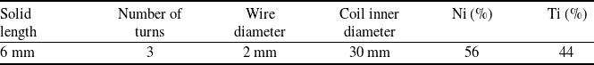
A NiTi SMA spring exhibiting a one-way shape memory effect was utilised as the primary actuation element of the mechanism. NiTi-based SMAs are widely employed in aerospace and precision actuation systems due to their high energy density, relatively superior corrosion resistance compared to other SMA compositions. These materials are capable of generating significant mechanical force through thermally induced phase transformations between the martensite and austenite phases, making them particularly suitable for compact actuator systems operating in spatially constrained environments. The selected SMA spring has an A f of 45 °C, and its key properties are presented in Table 2.
Physical properties of the SMA actuator

Landing gear door lock mechanism.

Figure 3 Long description
The diagram illustrates a landing gear door lock mechanism. It features a tension spring, an integrated safety lock, a self-locking lock mechanism, housing, a NiTi-based shape memory alloy (SMA) actuator, a piston, and a hook. The tension spring is positioned on the left side, while the integrated safety lock is located near the bottom left. The self-locking lock mechanism is at the top right, and the housing encloses the entire mechanism. The NiTi-based SMA actuator is situated in the middle right, connected to the piston, which extends downward to the hook at the bottom right.
The force exerted by a conventional coil spring, f, when deformed by a displacement δ, is described by Hooke’s Law, as expressed in Equation (1),
 \begin{align}f = K\delta \end{align}
where K is the spring stiffness. For a helical spring, the stiffness can be expressed as a function of the material and geometric properties, as shown in Equation (2) [Reference Kim, Lee, Park and Park34]. Specifically, G is the shear modulus of the material, d is the wire diameter, D is the mean coil diameter and N is the number of active coils.
 \begin{align}f = \frac{{G{d^4}\delta }}{{8{D^3}N}}\end{align}
2.2 Joule heating
The actuation of the NiTi-based SMA spring in the proposed mechanism is achieved through resistive (Joule) heating. Electrical current supplied via terminals at both ends of the spring generates heat internally due to the alloy’s electrical resistance. As temperature rises, the SMA undergoes a phase transformation from martensite to austenite, resulting in contraction and mechanical output [Reference Mavroidis35]. This process follows the electrical power dissipation principle, as expressed in Equation (3).
 \begin{align}P = \;IV\; = \frac{{{V^2}}}{R}\;\end{align}
While the electrical power dissipation is described by this fundamental principle, the resulting thermal response and phase transformation of the SMA spring are governed by a more detailed energy balance. This balance accounts for the heat generated internally by the current, the latent heat absorbed during the martensitic phase transformation and the convective heat loss to the ambient environment. This thermodynamic process can be modeled using an adaptation of the one-dimensional heat transfer equation proposed in the literature [Reference Hadi, Yousefi-Koma, Elahinia, Moghaddam and Ghazavi36], as shown in Equation (4).
 \begin{align} m{C_p}\frac{dT}{dt} + mL\dot \xi &= \frac{{{V^2}}}{R} - hA\left( {T - {T_\infty }} \right) \end{align}
 \begin{align} R &= {R_A} + \xi \left( {{R_M} - {R_A}} \right) \end{align}
Here, m represents the mass of the SMA spring, C
p is the specific heat capacity, T is the temperature, L is the latent heat of transformation and ξ˙ is the rate of change of the martensite fraction. The term V
2/R corresponds to the electrical power input, while h is the convection heat transfer coefficient, A is the surface area of the spring and T
∞ is the ambient temperature. In addition, the term R is expressed in terms of ${R_A}$
and
${R_A}$
and ${R_M}$
, which correspond to the electrical resistance in the austenite and martensite phases, as presented in Equation (5). This model provides a comprehensive framework for understanding the thermal dynamics that drive the mechanical output of the actuator.
${R_M}$
, which correspond to the electrical resistance in the austenite and martensite phases, as presented in Equation (5). This model provides a comprehensive framework for understanding the thermal dynamics that drive the mechanical output of the actuator.
Joule heating is preferred for SMA activation because of its simplicity, precise controllability and compatibility with embedded systems. It removes the need for external heat sources or complex thermal management, making it especially suitable for aerospace applications with severe limits on weight, volume and system complexity. However, careful regulation of current is essential to avoid overheating, which may degrade the SMA’s functional qualities and reduce operational lifespan. For aerospace applications, where actuator systems are required to operate under ambient temperatures ranging from −55 °C to +80 °C [Reference Sciascera, Giangrande, Brunson, Galea and Gerada37], a closed-loop control strategy is adopted as a design approach, in which thermal and electrical feedback obtained from the actuator system is used to estimate the SMA state. Based on this feedback, the activation energy supplied to the SMA can be adjusted to accommodate varying environmental conditions and to support stable actuation performance.
Future iterations will incorporate a closed-loop control system to guarantee operational consistency under various environmental circumstances, even if the current implementation depends on a fixed-power open-loop technique. Activation precision can be improved, and functional failure can be avoided by a feedback loop that uses temperature sensors or position sensors (e.g. Hall effect or linear variable differential transformer (LVDT)). In particular, the controller can dynamically increase the voltage and current to provide quick thermal compensation if the mechanism is unable to achieve the necessary 7 mm stroke because of extreme ambient cold during flight. This will guarantee that the unlocking time stays within the expected duration. On the other hand, the feedback system can control active cooling in high-temperature settings to preserve quick cycle times. Moreover, closed-loop control is essential for reducing the effects of SMA functional fatigue; the control algorithm can modify power parameters to compensate for changes in transformation temperatures and preserve the necessary mechanical output as the NiTi material degrades over thousands of cycles. By combining proportional-integral-derivative (PID) or fuzzy logic controllers with pulse width modulation (PWM), accurate energy management would be possible, preventing overheating and drastically lowering power usage during steady-state periods [Reference Sohn, Ruth, Yuk and Choi32].
2.3 Self-locking mechanism
The mechanism features a passive self-locking behaviour that maintains its locked position without the requirement for constant electrical power or additional actuation forces. This feature is achieved by properly locating a mechanical critical moment point, which creates a transition threshold between the locked and unlocked states. When in its passive condition, an external load supplied to the hook provides a clockwise torque that sustains the locked configuration of the system, as indicated in Fig. 4a.
When activated, the SMA spring is electrically heated beyond its activation temperature, inducing contraction and generating a stroke of approximately 7 mm, which retracts the piston and enables the release of the lock, as depicted in Fig. 4b.
A significant feature of the design comes in the mechanism’s capacity to maintain its current condition, either active or passive, without any external interference. This characteristic is ensured by the precise positioning of the critical moment point and the integration of tension springs under preload, which maintain the mechanism in its actuated state and prevent inadvertent resetting without the introduction of an external force. As the SMA material cools, the memory effect dissipates; however, in the presence of an external force applied to the hook, the preloaded tension spring is re-engaged, automatically restoring the mechanism to its original locked configuration, as demonstrated in Fig. 4c.
2.4 Secondary safety lock
The secondary safety lock is incorporated as an essential redundant element to guarantee the operational integrity of the mechanism in failure scenarios. A principal challenge in SMA applications is the potential for inadvertent activation caused by uncontrolled Joule heating, which may arise from electrical short circuits or severe ambient thermal conditions. The secondary lock functions as a mechanical barrier that physically inhibits the hook’s rotational trajectory, regardless of whether the primary SMA spring attains its transformation temperature prematurely, as illustrated in Fig. 5.
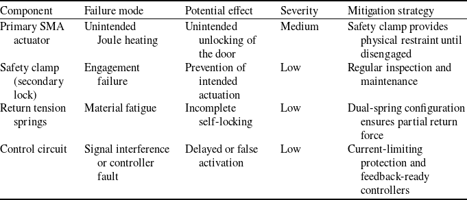
The operational sequence adheres to a defined safety protocol: the secondary clamp must be removed by a designated low-current instruction prior to the primary actuator commencing the unlocking stroke. This dual-stage activation guarantees that the system stays in a ‘fail-safe’ condition over extended flying phases. A preliminary failure modes and effects analysis (FMEA) was conducted to thoroughly assess the reliability of this architecture, as summarised in Table 3.
Self-locking mechanism. (a) Locked state (b) unlocked state (c) self-locking state.

Figure 4 Long description
The illustration depicts a self-locking mechanism in three different states: locked, unlocked, and self-locking. In the locked state, the mechanism is shown with arrows indicating the direction of movement, highlighting how the components are interlocked. In the unlocked state, the mechanism is depicted with arrows showing the components moving apart, allowing for the release. In the self-locking state, the mechanism is illustrated with arrows indicating how the components re-engage to lock automatically. The arrows in each state demonstrate the direction of force and movement, emphasizing the functional aspects of the self-locking mechanism.
Secondary safety lock.

Figure 5 Long description
The diagram illustrates a secondary safety lock mechanism. On the left side, the components are labeled as Clamp, Slider, and Track. On the right side, the components are labeled as Housing and Piston. The diagram shows the structural relationship between these parts, indicating how they interact within the mechanism.
This safety analysis reveals that the secondary lock, despite increasing the mechanism’s complexity, is crucial for limiting dangers associated with heat or electronic breakdowns. The design attains the high reliability criteria necessary for aircraft conditions by separating the safety restraint from the principal actuation force.
2.5 Cooling system design
Effective temperature management is a critical design consideration for ensuring the functional reliability and cycle repeatability of SMA-actuated systems. In the proposed mechanism, rapid cooling of the NiTi-based SMA compression spring is essential to minimise the residual force associated with the shape memory effect during the austenitic phase. As the SMA cools and transitions back to the martensitic phase, the generated actuation force progressively decreases, allowing the preloaded tension springs to regain mechanical dominance and return the system to its self-locking configuration.
Preliminary FMEA for the locking mechanism

Table 3 Long description
The table presents a failure modes and effects analysis (FMEA) for the locking mechanism, focusing on components, failure modes, potential effects, severity, and mitigation strategies. It includes four columns: Component, Failure mode, Potential effect, Severity, and Mitigation strategy. The table has five rows, each detailing a specific component and its associated failure modes. The Primary SMA actuator has a failure mode of unintended Joule heating, which could lead to the unintended unlocking of the door, with a medium severity level. The safety clamp, acting as a secondary lock, may experience engagement failure, preventing intended actuation, with a low severity level. The return tension springs are subject to material fatigue, causing incomplete self-locking, also with low severity. The control circuit may face signal interference or controller fault, resulting in delayed or false activation, again with low severity. Mitigation strategies include a safety clamp for physical restraint, regular inspection and maintenance, a dual-spring configuration for partial return force, and current-limiting protection with feedback-ready controllers.
Overall view of the cooling system.

Figure 6 Long description
The image displays a cooling system featuring a rectangular component with a protruding element extending from its side. The protruding element is connected to a smaller rectangular section, which appears to be part of the cooling mechanism. The system is depicted in a three-dimensional view, highlighting its structural design and components.
For aerospace applications, actuator systems are generally required to operate reliably under repeated thermal cycles across a wide ambient temperature range, typically from −55 °C to +80 °C. Accordingly, the SMA material must be selected based on its martensite–austenite phase transformation temperatures (A s , A f , M s , M f ) to ensure proper phase transition and actuation performance within this operational envelope. To maintain consistent recovery and thermal stability under varying ambient conditions, a closed-loop cooling approach is considered as a potential design strategy, in which the application of coolant would be adjusted based on the SMA temperature. The overall configuration of the cooling system is illustrated in Fig. 6. This approach aims to support repeatable actuation and minimise residual forces without relying solely on ambient temperature, while remaining at the conceptual stage in the present study.
Experimental observations indicate that the use of a coolant-assisted cooling method provides effective and repeatable recovery behaviour, contributing to improved thermal stability and reduced response time. To facilitate the practical implementation of this thermal management strategy and ensure efficient heat rejection from the internal environment to the ambient atmosphere, the physical architecture of the mechanism is optimised. Ventilation grills located on the exterior casing are retained to support passive heat dissipation and to facilitate the removal of residual heated air from the SMA chamber, as illustrated in Fig. 7. The combined use of controlled cooling and passive heat dissipation enhances the overall thermal robustness of the system without increasing structural complexity, making the proposed cooling design suitable for aerospace applications subject to fluctuating environmental conditions.
Ventilation grills.

Locked state.

Figure 8 Long description
The diagram illustrates a mechanical system in a locked state. It features a series of interconnected components, including springs, levers, and gears. A red dot indicates a specific point of interest. Green lines outline the boundaries and connections between different parts of the system. The overall structure suggests a complex interaction of mechanical elements designed to function together in a specific configuration.
3.0 Modelling and analysis of the mechanism
3.1 Kinematic analysis
2D analyses were performed using CATIA V5 to evaluate the motion characteristics of the mechanism. The critical parameters identified were: (i) the moment threshold point governing the transition between locked and unlocked states; (ii) the minimum required stroke; and (iii) the placement of the biased tension spring pair, as illustrated in Figs. 8 and 9. The mutual interaction among these factors directly affects both the energy demand on the actuator and the overall dimensions of the design. A collective consideration during the optimisation process is essential to ensure reliable actuator performance and compliance with dimensional requirements.
Unlocked state.

Figure 9 Long description
The diagram illustrates an unlocked mechanical system with various interconnected components. The structure includes circular and rectangular elements linked by lines, representing mechanical connections. Green lines trace the movement or interaction paths between these components. A red dot is present near the top left, possibly indicating a critical point or control mechanism. The overall layout suggests a complex system with specific points of articulation and motion.
Free body diagram of the lock mechanism.

Figure 10 Long description
The free body diagram of the lock mechanism illustrates the forces acting on different points within the system. The diagram includes a spring with preload forces at both ends, labeled as F preload. Several points, labeled O1 through O8, represent different locations where forces interact. Arrows indicate the direction and type of forces, such as F unlock, F load, and various Fx and Fy components. The diagram also shows the relationships between these points and forces, demonstrating how they contribute to the overall function of the lock mechanism.
Based on iterative 2D kinematic evaluations, the mechanism was systematically refined in two dimensions: the moment threshold and spring placement were precisely defined, and the necessary stroke length was reduced to 7 mm. The optimised stroke length reduced the force requirement on the SMA spring, improving energy efficiency and facilitating a more compact and mechanically robust mechanism capable of reliable locking and unlocking, which is essential for lightweight, high-performance systems.
In parallel, the configuration of the preloaded tension spring was refined to ensure autonomous return to the locked position after actuation. The spring was engineered to achieve its maximum extension during the unlocking motion, thereby generating sufficient restoring force and ensuring mechanical stability in both operational states without requiring external resetting. Consequently, the conducted 2D kinematic analyses established the fundamental framework of the mechanism and provided a solid foundation for the upcoming 3D modelling and dynamic simulation stages.
3.2 Static model
The static model can be derived from the force and moment equilibrium equations, which are obtained from Newton’s laws of motion under static equilibrium conditions. As shown in Fig. 10, there are four primary elements and ten state variables in the hook lock mechanism. The main objective of these formulations is to determine the unlocking force, f
unlock
, required for the actuation of the hook mechanism. Here, ${f_{load}}$
is the load force;
${f_{load}}$
is the load force; $f_{ij}^x$
is the force between the ith component and the jth component inthe x direction;
$f_{ij}^x$
is the force between the ith component and the jth component inthe x direction; $f_{ij}^y$
is the force between the ith component and the jth component in the y direction;
$f_{ij}^y$
is the force between the ith component and the jth component in the y direction; ${f_{preload}}\;$
is the spring force;
${f_{preload}}\;$
is the spring force; $f_{preload}^x$
is the spring force in the x direction;
$f_{preload}^x$
is the spring force in the x direction; $f_{preload}^y$
is the spring force in the y direction;
$f_{preload}^y$
is the spring force in the y direction; $f_{g4}^x$
is the force from the lock bracket to the jth component in the x direction; and
$f_{g4}^x$
is the force from the lock bracket to the jth component in the x direction; and $f_{g4}^y$
is the force from the lock bracket to the jth component in the y direction.
$f_{g4}^y$
is the force from the lock bracket to the jth component in the y direction.
The static equilibrium of the mechanism is established by formulating the force and moment balance of the four primary elements. These relations are expressed in Equations (6)–(14). Ultimately, the unlocking force of the mechanism $,\;{f_{nlock\;}}$
, is determined from the force equilibrium given in Equation (15).
$,\;{f_{nlock\;}}$
, is determined from the force equilibrium given in Equation (15).
 \begin{align} \sum {F_x}\;:\;f_{34}^x - f_{g4}^x &= 0 \end{align}
 \begin{align} \sum {F_y}\;:\;f_{g4}^y - f_{34}^y - {f_{load}} &= 0 \end{align}
 \begin{align} \sum {M_{{O^7}}}\;:\;{f_{load}} \cdot \left| {l_{{O^7}{O^8}}^x} \right| - f_{34}^y \cdot \left| {l_{{O^6}{O^7}}^x} \right| - f_{34}^x \cdot \left| {l_{{O^6}{O^7}}^y} \right| &= 0 \end{align}
 \begin{align} \sum {M_{{O^6}}}\;:\;{f_{load}} \cdot \left| {l_{{O^6}{O^8}}^x} \right| - f_{g4}^y \cdot \left| {l_{{O^6}{O^7}}^x} \right| - f_{g4}^x \cdot \left| {l_{{O^6}{O^7}}^y} \right| &= 0 \end{align}
 \begin{align} \sum {F_x}\;:\;f_{23}^x - f_{34}^x &= 0 \end{align}
 \begin{align} \sum {F_y}\;:\;f_{34}^y - f_{23}^y &= 0 \end{align}
 \begin{align} \sum {F_x}\;:\;f_{12}^x + f_{g2}^x + f_{preload}^x - f_{23}^x &= 0 \end{align}
 \begin{align} \sum {F_y}\;:\;f_{23}^y - f_{preload}^y + f_{g2}^y &= 0 \end{align}
 \begin{align} \sum {M_{{O^3}}}\;:\;f_{12}^x \cdot \left| {l_{{O^2}{O^3}}^y} \right| + f_{preload}^y \cdot \left| {l_{{O^3}{O^4}}^x} \right| - f_{preload}^x \cdot \left| {l_{{O^3}{O^4}}^y} \right| + f_{23}^y \cdot \left| {l_{{O^3}{O^5}}^x} \right| - f_{23}^x \cdot \left| {l_{{O^3}{O^5}}^y} \right| &= 0 \end{align}
 \begin{align} \sum {F_x}\;:\;{f_{unlock}} - f_{12}^x &= 0 \end{align}
3.3 Dynamic analysis
Iterative dynamic analyses were conducted using MSC Adams software to evaluate the force requirements of the NiTi-based SMA spring and the preloaded tension spring under an external load of 20 N. This configuration corresponds to the per-lock requirement for a dual-lock architecture, yielding a total holding force of 40 N, representative of lightweight closure mechanisms implemented in small-scale UAV platforms. The selection of a thermoplastic material system served as a primary determinant in establishing the 20 N load threshold. In this prototype-scale investigation, polyethylene terephthalate glycol (PETG) was selected for laboratory validation owing to its adequate impact strength and thermal resistance, thereby ensuring operational integrity without permanent structural deformation. Furthermore, the underlying mechanism remains inherently scalable; by integrating SMA actuators with distinct thermomechanical and physical profiles, the system can be adapted to meet higher load requirements in various UAV platforms.
These analyses identified the minimum SMA activation force (austenite phase) and the maximum resistive force (martensite phase), and a robust linear relationship between these forces is revealed in Fig. 11. In Fig. 12, the mechanism’s stroke throughout its operational cycle is illustrated. The force profile under a 36 N activation force with a 16 N resistive force (the system remains functional for resistive forces below 19 N) is presented in Fig. 13. These results were validated through laboratory testing, highlighting the predictive accuracy of the dynamic model.
Dynamic analysis results indicating stable system operation based on minimum activation and maximum resistance force.

Figure 11 Long description
A line graph with two data lines representing the relationship between tension spring preload in Newtons on the x-axis and two forces in Newtons on the y-axis. The blue line represents the minimum activation force, ranging from approximately 15 Newtons to 45 Newtons as the preload increases from 0 Newtons to 40 Newtons. The orange line represents the maximum resistance force, ranging from approximately 0 Newtons to 25 Newtons as the preload increases from 0 Newtons to 40 Newtons. Both lines show a positive linear trend, indicating that as the tension spring preload increases, both the minimum activation force and the maximum resistance force also increase. All values are approximated.
SMA stroke analysis.

SMA force analysis.

Figure 13 Long description
The line graph titled SMA force analysis features a single data line representing force in newtons over time in seconds. The y axis ranges from 0 to 40 newtons, while the x axis spans from 0 to 4 seconds. The force starts at 0 newtons, increases rapidly to around 35 newtons by 1 second, maintains this level until approximately 2 seconds, and then drops sharply to 15 newtons, where it remains constant for the rest of the observed time. All values are approximated.
4.0 Prototype development and fabrication process
Prototype development was undertaken as the subsequent stage of the study, focusing on the design and fabrication of test fixtures to enable realistic operational evaluation of the mechanism. The prototype test setup, shown in front and back isometric views in Figs 14 and 15, demonstrates the full arrangement and integration of the test fixtures. A dedicated test fixture was first designed to securely hold the main mechanism assembly. Furthermore, considering the limited availability of data in the literature concerning the force–extension characteristics of the SMA, an adjustable test fixture was incorporated into the internal design of the prototype to facilitate systematic experimental investigations. For this purpose, a movable lead screw test setup, employing a bolt–nut system, was designed and directly integrated into the prototype, enabling the characterisation of the SMA spring by allowing for its precise positioning at various extensions during the testing phase. Through this characterisation process, the definitive force requirements for reliable actuation were determined. The prototype was also intentionally designed with extended dimensions to facilitate these iterative tests, and tolerance ranges were applied during the design phase to ensure smooth assembly.
Prototype test setup front view.

Prototype test setup rear view.

Figure 15 Long description
The image shows a rear view of a prototype test setup. The setup includes a mechanical assembly with a spring and an actuator. The actuator is likely an SMA (Shape Memory Alloy) element working against the spring. The assembly is mounted on a sturdy base with various components and connections visible. The setup appears to be designed for testing the performance and functionality of the SMA actuator under different conditions.
The prototype components were fabricated using fused deposition modelling (FDM), an additive manufacturing technique. Material selection and thermal management for the FDM process were critical considerations during the fabrication process. The heat generated during this process must be carefully considered due to the thermal limitations of polylactic acid (PLA) material. The deformation temperature of PLA under load ranges from 50 to 140 °C, and the operating temperatures required for SMA (usually 60–70 °C) are close to the lower limit of this range, providing a risk of deformation under localised heating. PLA was shown to have strong mechanical properties after printing (tensile strength of 54–64 MPa, elastic modulus around 3.3–3.6 GPa) and low thermal expansion, making it resistant to surface deformation; however, its limited thermal resistance requires careful application in thermally active systems [Reference Letcher and Waytashek38]. Despite this, PLA remains advantageous for prototyping because of its eco-friendly nature, ease of usage and high print quality, provided that smart design choices are made in areas of direct contact. In this study, we utilised the advantages of PLA filament during the prototyping phase of the mechanism’s enclosure. To prevent thermal deformation and loss of dimensional accuracy caused by localised heating, PETG filament was used throughout the main structure of the mechanism. PETG’s higher glass transition temperature and improved thermal degradation resistance while maintaining good mechanical strength and printability make it a more suitable choice for components exposed to the actuation heat generated by the SMA wire. Its stable morphology and low thermal expansion further ensure structural integrity under repeated thermal cycling, thereby enhancing the reliability of the overall system. Notably, PETG has been shown to maintain a homogeneous microstructure even when blended with recycled content, with degradation onset temperatures exceeding 320 °C and glass transition temperatures remaining above 70 °C, indicating robust thermal stability under processing and operating conditions [Reference Latko-Durałek, Dydek and Boczkowska39].
Regarding the materials and infill densities used in the fabrication, the hook lock mechanism was printed using PETG filament with a 70% infill density to ensure enhanced mechanical strength and durability required for its functional performance. In contrast, the test rig was fabricated with PETG at a lower infill density of 30%, balancing sufficient structural integrity with material efficiency and reduced printing time.
For material selection, PLA and PETG were employed during the fast-prototyping phase to facilitate iterative design modifications and functional validation at a reduced cost. However, it is known that these polymers possess thermal properties such as glass transition temperatures ( ${T_g}$
) about 60–80°C that are above the SMA’s activation temperature (45°C). PETG was used for the primary structure because of its enhanced thermal stability and elevated glass transition temperature (75°C) relative to PLA; nonetheless, these materials are not suitable for final aircraft certification [Reference Latko-Durałek, Dydek and Boczkowska39, Reference Hsueh, Lai, Wang, Zeng, Hsieh, Pan and Huang40]. For a flight-qualified variant, high-performance materials like Aluminum 7075-T6 would be employed to mitigate issues related to thermal deformation and creep under prolonged mechanical stress. These metallic materials give much better thermal conductivity, assisting in the passive cooling of the SMA, and offer the structural integrity required to survive the vibration and climatic extremes characteristic of UAV operational environments.
${T_g}$
) about 60–80°C that are above the SMA’s activation temperature (45°C). PETG was used for the primary structure because of its enhanced thermal stability and elevated glass transition temperature (75°C) relative to PLA; nonetheless, these materials are not suitable for final aircraft certification [Reference Latko-Durałek, Dydek and Boczkowska39, Reference Hsueh, Lai, Wang, Zeng, Hsieh, Pan and Huang40]. For a flight-qualified variant, high-performance materials like Aluminum 7075-T6 would be employed to mitigate issues related to thermal deformation and creep under prolonged mechanical stress. These metallic materials give much better thermal conductivity, assisting in the passive cooling of the SMA, and offer the structural integrity required to survive the vibration and climatic extremes characteristic of UAV operational environments.
5.0 Experimental setup and testing
An experimental investigation was conducted to characterise the thermomechanical performance of the SMA-actuated hook lock mechanism, with the experimental arrangement depicted in Fig. 16. The test procedure was structured sequentially, commencing with preliminary force-output evaluation of the NiTi SMA spring. The data obtained from these initial tests informed the parameters for the comprehensive performance evaluation of the final assembled mechanism.
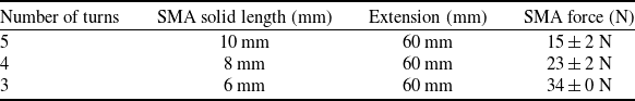
The characterisation of the NiTi SMA spring’s force-producing capability was conducted prior to testing the fully assembled mechanism. The output force of the SMA spring was measured using a dynamometer under multiple configurations, employing springs with different coil counts at a constant extension of approx. 60 mm, as detailed in Table 4. For three-turn SMA spring configuration, a mean contraction force of 34 N was obtained. This selection is justified by the fact that its contraction force provides a sufficient operational margin over the 32 N minimum activation threshold required to initiate the mechanical stroke.
Number of turns - SMA activation force/dynamometer test

Laboratory test setup.

Figure 16 Long description
A laboratory test setup featuring a machine with a control box connected by wires. The control box has a display screen and several knobs. The machine includes a mechanical arm and a component that appears to be a 3D printer or similar device. A cardboard box is placed on the floor next to the machine.
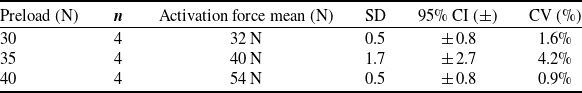
A critical aspect of the design was ensuring that the mechanism could reliably return to its locked state. To determine the required restoring force, a static force analysis was performed, which indicated that a preload force exceeding 25 N was necessary to overcome the residual resistance of the SMA spring in its martensite phase and to generate sufficient moment for the mechanism to return to its self-locking position. To provide a greater safety margin and enhance overall performance, a 30 N preloaded tension spring was selected for the final test configuration. The minimum SMA activation force associated with each preload condition was determined experimentally, with at least four independent trials conducted per configuration to ensure reproducibility. The consistency of these actuation thresholds was validated through a comprehensive statistical analysis, including mean values, standard deviations, 95% confidence intervals (based on Student’s t-distribution) and coefficients of variation (CV) to quantify measurement dispersion. As summarised in Table 5, the selected configuration requires a minimum SMA activation force of 32 ± 0.8 N.
Tension spring - activation force/dynamometer test

Based on stability and safety criteria, a three-turn SMA spring and a 30 N preloaded tension spring were selected as the final components and incorporated into the mechanism to evaluate its operational force response. Activation and resistance forces were measured at varying SMA extensions to assess the mechanism’s stable operating conditions. As illustrated in Fig. 17, the force values in both the austenitic and martensitic phases exhibit a positive correlation with increasing SMA extension. However, the force increase in the austenitic phase, representing the activation force, follows a non-linear progression by rising from 16 N to 35 N as extension increases. In contrast, the force response in the martensitic phase, corresponding to the resistance force, remains significantly more stable and follows an approximately linear trend ranging from 11 N to 17 N.
Experimental test results showing SMA activation force and resistance force for different extensions.

Figure 17 Long description
The line graph presents two data series: SMA activation force in the Austenite phase and SMA resistance force in the Martensite phase, both measured in Newtons. The x-axis represents extension in millimeters, ranging from 0 to 80 millimeters. The y-axis represents force in Newtons, ranging from 0 to 40 Newtons. The blue line indicates the SMA activation force, which increases steadily from approximately 15 Newtons at 20 millimeters to around 35 Newtons at 70 millimeters. The orange line represents the SMA resistance force, which rises gradually from about 10 Newtons at 20 millimeters to roughly 15 Newtons at 70 millimeters. All values are approximated.
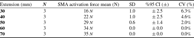
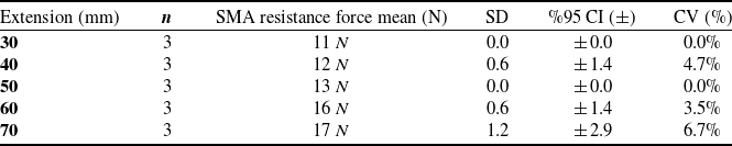
For each extension level, a minimum of three measurements were conducted to establish a robust dataset, and the corresponding statistical analyses are summarised in Tables 6 and 7. Experimental results indicate that the mechanism operates reliably when the SMA actuator generates an activation force of 34 ± 0 N in the austenitic phase, while a passive resistance force of 16 ± 1.4 N is observed in the martensitic phase.
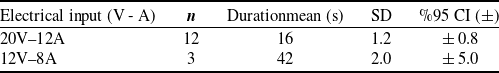
The time-based performance of the mechanism was evaluated, focusing on its activation and recovery times. The minimum activation time was determined by conducting a series of experiments under different electrical input conditions, as detailed in Table 8. Through these tests, which utilised resistive (Joule) heating to bring the SMA to its austenitic transition temperature, the time required for the spring to contract and fully unlock the mechanism was found to be 16 ± 0.8 s. Separately, the recovery phase was analysed to determine the cooling time. To assist the cooling of the mechanism, a directed coolant spray capable of providing a nominal outlet temperature of up to −50 °C was applied. Under these conditions, the minimum recovery time for the mechanism to return to its self-locking state was also observed to be approximately 15 s.
Extension - SMA activation force/dynamometer test

Table 6 Long description
The table presents data on SMA activation force for various extension levels, with columns for extension in millimeters, number of measurements, mean activation force in newtons, standard deviation, 95% confidence interval, and coefficient of variation in percentage. The extensions range from 30 to 70 millimeters, with corresponding mean activation forces from 16 to 35 newtons. The standard deviation varies from 0.0 to 1.0, and the 95% confidence interval ranges from 0.0 to 2.5. The coefficient of variation decreases from 6.3% to 0.0% as the extension increases.
Extension - SMA resistance force/dynamometer test

Table 7 Long description
The table presents data on SMA resistance force mean, standard deviation, confidence interval, and coefficient of variation for different extension levels in millimeters. It includes five rows for extension levels 30, 40, 50, 60, and 70 millimeters, each with three measurements. The columns are labeled Extension (mm), n, SMA resistance force mean (N), SD, %95 CI (±), and CV (%). For each extension level, the SMA resistance force mean ranges from 11 N to 17 N. The standard deviation varies from 0.0 to 1.2, the 95% confidence interval ranges from ±0.0 to ±2.9, and the coefficient of variation ranges from 0.0% to 6.7%. Notable trends include consistent SMA resistance force mean values with varying standard deviations and confidence intervals.
Activation time tests under varying current and voltage

Table 8 Long description
The table presents data on activation time tests conducted under varying electrical input conditions. It includes two rows and six columns. The columns are labeled Electrical input, n, Duration mean, SD, and percentage 95 CI. The first row shows data for an electrical input of 20 volts and 12 amperes, with 12 tests conducted, a mean duration of 16 seconds, a standard deviation of 1.2 seconds, and a 95 percent confidence interval of plus or minus 0.8 seconds. The second row shows data for an electrical input of 12 volts and 8 amperes, with 3 tests conducted, a mean duration of 42 seconds, a standard deviation of 2.0 seconds, and a 95 percent confidence interval of plus or minus 5.0 seconds.
5.1 Fatigue life and thermal cycle stability
NiTi-based shape memory alloys (SMAs) are widely employed in spring-type actuators due to their high recoverable strain capability (up to 8%), compact form factor and high actuation energy density, which make them suitable for force-generation applications in constrained volumes. In the literature, the fatigue behaviour of shape memory alloys is commonly categorised into structural fatigue, which is associated with crack initiation and fracture, and functional fatigue, which refers to the degradation of functional properties, including a reduction in shape memory or superelastic effects and an increase in the percentage of residual martensite with increasing cycle numbers [Reference Eggeler, Hornbogen, Yawny, Heckmann and Wagner41, Reference Yan, Wei, Chu, Wang, He, Ren and Sun42]. Owing to the inherently cyclic nature of such actuator applications, NiTi SMAs are commonly subjected to repeated thermomechanical loading. Under these conditions, the cyclic behaviour of NiTi SMAs is primarily discussed in terms of functional fatigue, which refers to the progressive degradation of functional characteristics such as actuator stroke, recoverable strain, plateau stresses, hysteresis width and transformation temperatures, rather than catastrophic structural failure. This degradation is attributed to the accumulation of transformation-induced defects in the microstructure [Reference Frenzel43]. For actuator-oriented applications, functional fatigue is often the dominant factor limiting long-term performance rather than structural fracture.
Reported experimental studies indicate that the functional fatigue behaviour of NiTi shape memory alloys is dominated by a pronounced early-cycle degradation stage, followed by a more stabilised cyclic response. As shown in Fig. 18, which reproduces strain-controlled low-cycle fatigue results obtained on NiTi wires by Lima et al., the functional characteristics of the NiTi wire were investigated through tensile loading–unloading tests conducted up to a maximum strain level of 6%. The results indicate that a substantial portion of the functional degradation occurs within the first 50–150 cycles. Specifically, Fig. 18(a) shows that the residual strain increases rapidly from approximately 0.2% to nearly 1.0%, while Fig. 18(b) indicates that the recoverable strain decreases from about 6.0% to approximately 5.0%, demonstrating that nearly 1% of the total transformation strain capacity becomes irreversible during early cycling. Concurrently, Fig. 18(c) illustrates a pronounced reduction in the direct transformation stress from approximately 360 MPa to about 230 MPa, and Fig. 18(d) shows a decrease in the dissipated energy per cycle from roughly 140 J/m3 to 80 J/m³, highlighting a significant loss in actuation capability despite the absence of macroscopic fracture [Reference Lima, Rodrigues, Ramos, Costa, Braz Fernandes and Vieira44].
Mechanical behaviour of NiTi wire. (a) Residual strain; (b) recovered strain; (c) direct transformation stress and (d) dissipated energy versus function of the number of cycles [Reference Lima, Rodrigues, Ramos, Costa, Braz Fernandes and Vieira44].

Figure 18 Long description
The four line graph illustrates the mechanical behavior of NiTi wire over a number of cycles. The x-axis represents the number of cycles, ranging from 0 to 300. The y-axis for each graph represents different mechanical properties: residual strain in percentage, recovered strain in percentage, direct transformation stress in megapascals, and dissipated energy in joules per cubic meter. The first graph shows an increasing trend in residual strain, starting from approximately 0.2 percent and leveling off around 1.2 percent. The second graph depicts a decreasing trend in recovered strain, starting from around 6 percent and stabilizing near 4.8 percent. The third graph shows a sharp decline in direct transformation stress, starting from about 360 megapascals and dropping to around 220 megapascals. The fourth graph illustrates a decreasing trend in dissipated energy, starting from approximately 150 joules per cubic meter and leveling off around 60 joules per cubic meter. All values are approximated.
Beyond this initial transient regime, Fig. 18 further demonstrates that the evolution of residual strain, recoverable strain, transformation stress and dissipated energy proceeds at markedly reduced rates, indicating the establishment of a stabilised cyclic response [Reference Lima, Rodrigues, Ramos, Costa, Braz Fernandes and Vieira44]. Previous studies have demonstrated that the fatigue behaviour of SMAs is strongly governed by microstructural evolution and its influence on the stress–strain hysteresis during cyclic loading. Appropriate thermomechanical treatments can stabilise the cyclic response and mitigate strain localisation, thereby enhancing functional stability. In pseudo-elastic operation, maintaining the transformation plateau stress below the yield stress of the austenitic phase effectively limits dislocation generation during cyclic loading, leading to reduced accumulation of residual strain. Nevertheless, even under optimised conditions, irreversible strain accumulation cannot be completely avoided, as continued cyclic loading promotes progressive increases in dislocation density and the stabilisation of martensitic variants that do not fully transform back to the austenitic phase upon unloading [Reference Eggeler, Hornbogen, Yawny, Heckmann and Wagner41].
From a strain-based perspective, the degree of functional fatigue can be quantitatively estimated using the reduction in recoverable strain. As shown in Fig. 18(b), the recoverable strain decreases from approximately 6.0% in the initial cycles to about 5.0% after 100–150 cycles, corresponding to a relative functional degradation of approximately 16–17% with respect to the initial recoverable strain. This strain-based fatigue metric provides a physically meaningful functional performance loss under cyclic thermomechanical loading.
In the present study, the NiTi-based SMA spring actuator was subjected to more than 100 thermomechanical activation cycles, with cooling predominantly achieved via two distinct approaches, namely forced convection and refrigerant-based cooling. The actuator, featuring a three-loop configuration and a solid-state length of 6 mm, was extended to approximately 60 mm during operation, corresponding to a nearly tenfold displacement relative to its initial length. When interpreted in terms of the reduction in force generation capability, the functional fatigue of the SMA spring actuator is estimated to be approximately 10%.
Although the results presented in Fig. 18 were obtained from uniaxial strain-controlled fatigue tests on NiTi wires, they provide valuable insight into the intrinsic material-level mechanisms governing functional fatigue in NiTi alloys. Consequently, while the absolute stress and strain values may differ due to geometric effects, the trends observed in Fig. 18, namely rapid functional degradation at low cycle numbers followed by a stabilised fatigue regime, are expected to remain qualitatively valid for spring-type SMA actuators.
Regarding the thermal cycle stability, the mechanism was activated for 12 cycles under controlled electrical parameters of 20 V and 12 A. The activation duration yielded a mean value of 16 s. Statistical analysis revealed that the deviation remained within a narrow margin, characterised by a 95% confidence interval (CI) of ±0.8 s. This high level of precision and the negligible variance across thermal cycles demonstrate the exceptional repeatability and operational stability of the mechanism under the specified conditions.
6.0 Discussion
Regarding the energy requirements of the suggested mechanism, the energy consumption per cycle was determined as around 3.6 kJ, based on the experimental conditions of 20 V and 12 A over a 15-second activation time. Within the framework of analysing actuator performance metrics [Reference Arias Guadalupe, Copaci, Serrano del Cerro, Moreno and Blanco45], the overall efficiency of the design is analysed using a comprehensive system-level mass penalty perspective [Reference Götten, Finger, Havermann, Braun, Gómez and Bil46]. Conventional actuation systems, including those based on hydraulic or electromechanical principles, need large sub-components such as electric motors, gearboxes, or hydraulic pumps and reservoirs that can increase the total weight of a landing gear system by 15% to 25% [Reference Götten, Finger, Havermann, Braun, Gómez and Bil46, Reference Kling and Hornung47].
In this context, the SMA-based design provides a considerable net positive influence on the UAV’s total energy efficiency by eliminating these bulky components and reducing the overall aircraft mass. This mass reduction is particularly crucial for UAV-class aircraft, because every saved gram immediately correlates to lower propulsive power usage over the full flight envelope [Reference Uragun48]. Furthermore, the passive self-locking nature of the mechanism assures that no energy is spent during the long-duration locked periods of flight, unlike hydraulic systems that require continual pressure maintenance [Reference Karunanidhi, Manoharan and Rajamanickam49]. Consequently, the larger localised energy pulse required for unlocking is effectively offset by the persistent reduction in aerodynamic and structural energy costs offered by the simpler, lightweight architecture.
7.0 Conclusion
In this study, the design, optimisation and experimental verification of a novel hook lock mechanism actuated by an SMA for UAV landing gear doors are provided. The primary goal was to develop a lightweight, compact, and energy-efficient alternative to traditional hydraulic, pneumatic or electromechanical systems, which are often complex and prone to failure. The final design effectively integrates an active unlocking function, driven by the thermal activation of a NiTi-based SMA spring, with a passive self-locking capability ensured by preloaded tension springs.
The development process was systematic, beginning with a conceptual design derived from an extensive review of existing locking mechanisms. Key operational parameters were optimised through detailed analytical modelling. Two-dimensional kinematic analyses were crucial in defining the mechanism’s critical moment threshold and minimising the required actuator stroke to an efficient 7 mm. Following this, three-dimensional dynamic simulations in MSC Adams were performed to determine the precise force requirements for the SMA and tension springs under a 20 N operational load. A physical prototype was fabricated using FDM to validate the analytical findings. Comprehensive experimental tests were conducted to characterise the system’s performance, which led to the selection of an optimal configuration: a three-turn SMA spring combined with a 30 N preloaded tension spring. The results from these tests demonstrated a strong correlation with the dynamic simulation predictions, confirming the mechanical feasibility and reliability of the design.
The performance evaluation revealed a highly responsive system. A key finding was that the mechanism achieved both full activation via Joule heating and a complete return to its self-locking state via cooling in approximately 15 s. This cycle time is well-suited for the operational demands of landing gear systems during take-off and landing phases. In conclusion, this study validates that the developed SMA-based actuator is a compelling and viable alternative to conventional systems, offering a structurally simple, lightweight and energy-efficient solution for demanding aerospace applications.
Acknowledgements
This work was partially supported by Turkish Aerospace LIFT UP programme and TUBITAK (Scientific and Technological Research Council of Turkey) 2209B programme.
Competing interests
The author(s) declare that they have no competing interests.


 Open access