

Introduction
Beginning
As an introductory remark for readers of this review, I (U.B.S.) would like to emphasize that I have been fascinated by microbiological issues for 70 years now. I was given a microscope at the age of 10 and thus had the opportunity to explore the fascinating world of the microcosm very early in my life. However, the observation that the cell surface of prokaryotic organisms is covered with a coherent lattice structure was only possible with the help of electron microscopy. These observations were made almost 60 years ago and since then I have been intensively involved in studying this structure and its possible applications. In retrospect, it was a fascinating journey of discovery that began with a serendipitous observation and ultimately led to the recognition of S-layer proteins as one of the most abundant biopolymers on our planet with great potential as patterning element for nanobiotechnology and synthetic biology.
For a better understanding of our contributions in the field of fundamental and applied S-layer research, the following brief introductory overview of the entire field is intended. We (U.B.S. and D.P.) assume that on this basis our scientific contributions, which are not always presented chronologically, will be better understood.
Since the field of S-layer protein research has grown considerably since our initial discovery in the 1960s, it is impossible to cover the entire field in this review. Interested readers should consult reviews in which various aspects of basic and applied S-layer research were presented in detail (e.g., Sleytr et al., Reference Sleytr, Messner, Pum and Sára1999, Reference Sleytr, Sára, Pum and Schuster2001a,Reference Sleytr, Sára, Pum, Schuster and Rosoffb, Reference Sleytr, Sára, Pum, Schuster and Ciferri2005, Reference Sleytr, Schuster, Egelseer, Pum, Horejs, Tscheliessnig and Ilk2011, Reference Sleytr, Pum, Egelseer, Ilk, Schuster and Knoll2013, Reference Sleytr, Schuster, Egelseer and Pum2014, Šmarda et al., Reference Šmarda, Šmajs, Komrska and Krzyžánek2002; Albers and Meyer, Reference Albers and Meyer2011; Pavkov-Keller et al., Reference Pavkov-Keller, Howorka and Keller2011; Fagan and Fairweather, Reference Fagan and Fairweather2014; Raff et al., Reference Raff, Matys, Suhr, Vogel, Günther, Pollmann, Cortajarena and Grove2016; Rodrigues-Oliveira et al., Reference Rodrigues-Oliveira, Belmok, Vasconcellos, Schuster and Kyaw2017; Schuster and Sleytr, Reference Schuster and Sleytr2020; Bharat et al., Reference Bharat, von Kügelgen and Alva2021; Pfeifer et al., Reference Pfeifer, Ergal, Koller, Basen, Schuster and Rittmann2021; Buhlheller et al. Reference Buhlheller, Sagmeister, Grininger, Gubensäk, Sleytr, Usón and Pavkov-Keller2024).
A chronological overview of fundamental and applied S-layer research is shown in the timeline of ‘Selected milestones in basic and applied S-layer research’.
Selected milestones in basic and applied S-layer research

General description of S-layer proteins
Location and ultrastructure
Most prokaryotic organisms (Bacteria and Archaea) have well-defined supramolecular cell envelope structures that have developed during evolution because of selection in response to specific, often highly competitive habitats and environmental and ecological stresses. It is now well recognized that one of the most frequently observed prokaryotic cell envelope surface structures are monomolecular arrays of protein and glycoprotein subunits referred to as surface(S)-layers (Sleytr, Reference Sleytr1976) (Figures 1 and 2).
TEM micrographs of freeze-etched preparations of whole cells from (a) Thermoanerobacter thermoshydrosulfuricus L111-69 exhibiting an S-layer with hexagonal lattice symmetry, (b) Desulfotomaculum nigrificans NCIB 8706 with square lattice symmetry, and (c) Geobacillius stearothermophilus NRS 2004-3a with oblique lattice symmetry. In the cylindrical part of the rod-shaped cells, which are embedded in ice, the lattices exhibit a good long range order. In (a) and (b), one can recognize flagella that have collapsed on the cell surface during cell centrifugation. (Reproduced from Messner et al. Reference Messner, Pum and Sleytr1986b; Sleytr et al. Reference Sleytr and Beveridge1999, with permission)

Schematic illustration of the supramolecular architecture of the major classes of prokaryotic cell envelopes containing surface (S) layers. S-layers in Archaea with glycoprotein lattices as exclusive wall component are composed either of (a) mushroom like subunits with pillar like, hydrophobic trans-membrane domains or (b) lipid modified glycoprotein subunits. Individual S-layers can be composed of glycoproteins possessing both types of membrane anchoring mechanisms. (c) Few Archaea possess a rigid wall layer (e.g., pseudomurein in methanogenic organisms) as intermediate layer between the plasma membrane and the S-layer. In Gram-positive bacteria, (d) the S-layer (glyco)proteins are bound to the rigid peptidoglycan containing layer via secondary cell wall polymers. In Gram-negative bacteria, (e) the S-layer is closely associated with the lipopolysaccharide of the outer membrane. (Modified after Sleytr et al., Reference Sleytr, Schuster, Egelseer and Pum2014, with permission.)

Chemical and genetic analysis of many S-layers have revealed a similar overall composition. They are generally composed of a single protein or glycoprotein species with molecular masses ranging from 40 to 170 kDa (Sleytr et al., Reference Sleytr, Messner, Pum and Sára1993, Reference Sleytr, Messner, Pum and Sára1999, Reference Sleytr, Sára, Pum, Schuster, Messner, Schäffer, Steinbüchel and and Fahnestock2002, Reference Sleytr, Pum, Egelseer, Ilk, Schuster and Knoll2013, Reference Sleytr, Schuster, Egelseer and Pum2014; Messner et al., Reference Messner, Schäffer, Egelseer, Sleytr, König, Claus and Varma2010). Amino acid analysis of S-layer proteins of organisms from all phylogenetic branches revealed a rather similar overall composition (Messner and Sleytr, Reference Messner and Sleytr1992; Sára and Sleytr, Reference Sára and Sleytr1996; Messner et al., Reference Messner, Schäffer, Egelseer, Sleytr, König, Claus and Varma2010). Sequencing of genes encoding the S-layer proteins revealed that with a few exceptions (e.g., Lactobacillus), S-layers are composed of an acidic protein or glycoprotein species with an isoelectric point between pH 4 and 6 (Sleytr et al., Reference Sleytr, Pum, Egelseer, Ilk, Schuster and Knoll2013, Reference Sleytr, Schuster, Egelseer and Pum2014).
Since S-layer (glyco)proteins account for approximately 10% of cellular proteins in Bacteria and Archaea, they can be considered as one of the most abundant biopolymers on earth (Sleytr and Beveridge, Reference Sleytr and Beveridge1999; Schuster and Sleytr, Reference Schuster, Sleytr, Tien and Ottova2005). This is particularly true when one considers that the biomass of prokaryotic organisms probably surpasses the biomass of eukaryotic ones (Whitman et al., Reference Whitman, Coleman and Wiebe1998).
The discovery and early description of S-layers by electron microscopical and chemical studies mark a significant chapter in the understanding of prokaryotic cell envelopes, unravelling a complex world of structural and functional sophistication (Sleytr, Reference Sleytr1978; Sleytr and Glauert, Reference Sleytr, Glauert and Harris1982; Sleytr et al., Reference Sleytr, Schuster, Egelseer and Pum2014). Ultrastructural studies involving transmission electron microscopy (TEM) and scanning probe microscopy demonstrated that S-layer lattices can exhibit either oblique (p1, p2), square (p4) or hexagonal (p3, p6) space group symmetry whereby hexagonal symmetry is predominant among Archaea (Figure 3).
Schematic drawing of the different S-layer lattice types, their base vectors, their unit cells (shaded in grey), and the corresponding symmetry axis. The proteins at one morphological unit are shown in red. S-layer lattices can also be formally described as two-dimensional crystals. Based on the various symmetry elements, they can be divided into space groups. It is known that there are 230 three-dimensional space groups, while there are only 17 two-dimensional plane groups. Since these plane groups only provide information in a single plane, they are often called one-sided plane groups. However, a real planar crystal usually has two distinguishable faces which introduces a third direction and leads in this additional information to a total of 80 two-sided plane groups, or two-dimensional space groups (2D-space groups). A list of the 80 two-sided plane groups, divided with respect to their lattice types, can be found in reference (Pum et al. Reference Pum, Breitwieser and Sleytr2021). Nevertheless, real biological molecules, such as S-layer proteins, can never be related to each other – neither vertically nor laterally - by mirror or glide planes or inversion centres because they have a certain handedness - they are chiral. From the 80 two-sided plane groups, only 17 groups contain no mirror or glide planes or inversion centers and thus fulfill this requirement. Finally, S-layer proteins in an S-layer lattice can never be related to each other by two-fold axes in the layer plane, because in this case, one protein would lie next to another in reversed orientation (outer versus inner side). This is not possible, and thus, S-layer lattices have either only p1, p2, p4, p3, or p6 lattice symmetry. In fact, the remaining two-sided plane groups have never been observed in S-layers. (Reproduced from Pum et al., Reference Pum, Breitwieser and Sleytr2021, with permission).

Depending on the lattice symmetry, one morphological unit (unit cell) consists of one, two, three, four or six identical morphological (glyco)protein subunits, whereby the centre-to-centre spacings of the morphological units are about 5–30 nm. While some organisms have two superimposed S-layers with different lattice types, morphological units rarely consist of two different subunits (Watson and Remsen, Reference Watson and Remsen1970; Beveridge and Murray, Reference Beveridge and Murray1976; Stewart and Murray, Reference Stewart and Murray1982; Taylor et al., Reference Taylor, Deatherage and Amos1982; Sekot et al., Reference Sekot, Posch, Oh, Zayni, Mayer, Pum, Messner, Hinterdorfer and Schäffer2012; Gambelli et al., Reference Gambelli, Meyer, McLaren, Sanders, Quax, Gold, Albers and Daum2019). S-layers of Bacteria are 5–15-nm-thick and have a rather smooth outer surface and a more corrugated inner one. S-layers from Archaea generally exhibit a much thicker (c. 35 nm) ‘mushroom-like’ structure with pillar-like domains anchored to the plasma membrane or in a few species to a rigid wall component (e.g., pseudomurein) (Kandler, Reference Kandler, Sleytr, Messner, Pum and Sára1988). Moreover, S-layers are highly anisotropic structures with respect to their physicochemical surface properties (Sleytr et al., Reference Sleytr, Schuster, Egelseer and Pum2014). S-layers are highly porous protein lattices that have one or even several different classes of pores with diameters of 2–8 nm and cover up to approximately 70% of the surface. Thus, S-layers can be considered as the simplest biological membranes developed during evolution (Sleytr and Plohberger, Reference Sleytr, Plohberger, Baumeister and Vogell1980). In many species of bacteria, individual strains exhibit great diversity with respect to lattice symmetry and centre-to-centre spacings of the morphological units. These data, including chemical analyses and homology comparisons of protein sequences, suggest that, at least in bacteria, S-layers are non-conservative structures of limited taxonomic value. In some species, it was even demonstrated that individual strains are capable of synthesizing different S-layer proteins (Sára et al., Reference Sára, Pum, Küpcü, Messner and Sleytr1994; Sára et al., Reference Sára, Kuen, Mayer, Mandl, Schuster and Sleytr1996a).
It can be calculated that a closed S-layer on an average-sized, rod-shaped cell consists of around 500,000 monomers. Thus, in order to maintain a closed protein lattice on a rapidly growing cell (e.g., generation time 20 minutes), within a second, approximately 400–500 copies of a single (glycosylated) polypeptide species with a molecular weight of approximately 100 kDa must be synthesized, transferred to the cell surface and incorporated into the existing S-layer lattice in a defined orientation, whereby an arrangement with low free energy must be assumed (Sleytr, Reference Sleytr1975; Sleytr and Glauert, Reference Sleytr and Glauert1975; Sleytr and Messner, Reference Sleytr and Messner1983; Sleytr et al., Reference Sleytr, Messner, Pum and Sára1999, Reference Sleytr, Schuster, Egelseer and Pum2014).
Reassembly properties
The natural ability of isolated and purified S-layer proteins to reassemble after isolation and purification on cell surfaces, in solution, on solid supports, at the air–water interface and on lipid films, including liposomes and emulsomes, is one of their most important properties and has been fundamental to the wide range of applications over the last 40 years from life to material sciences (Egelseer et al., Reference Egelseer, Ilk, Pum, Messner, Schäffer, Schuster, Sleytr and Flickinger2010; Sleytr et al., Reference Sleytr, Schuster, Egelseer and Pum2014) (Figure 4).
In general, S-layers are isolated from cell wall fragments obtained by disrupting the cells and removing their contents including the cytoplasmic membrane. Most commonly, hydrogen-bond disrupting agents (e.g., guanidine hydrochloride (GHCl) or urea) are used to disintegrate the S-layer into its constituent subunits. Nevertheless, recombinant S-layer proteins and S-layer fusion proteins were most frequently used in our subsequent application-oriented work. Isolation of recombinant S-layer proteins from the host system was usually performed according to standard procedures developed for the isolation and purification of inclusion bodies from Escherichia coli. For a detailed description of the isolation, purification and/or recombinant production of S-layer proteins, the reader is referred to several reviews (Sleytr et al., Reference Sleytr, Schuster, Egelseer and Pum2014; Schuster and Sleytr, Reference Schuster and Sleytr2020). The isolated S-layer subunits from a variety of Bacteria revealed the ability to assemble spontaneously upon removing the disruptive agents (Sleytr, Reference Sleytr1978; Sleytr et al., Reference Sleytr, Sára, Pum, Schuster and Ciferri2005, Reference Sleytr, Schuster, Egelseer, Pum, Horejs, Tscheliessnig and Ilk2011).
The self-assembly products generated in suspension may have the form of flat sheets, open-ended cylinders or closed vesicles whereby depending on the assembly conditions mono- and double-layer products are obtained (Figure 4).
(a) Schematic drawing of the reassembly of isolated S-layer (glyco)proteins in solution, on solid supports, at the air–water interface, on lipid-films, on liposomes, emulsomes, polyelectrolyte nanocapsules or (magnetic) beads and on carbon nanotubes. TEM micrographs of negatively stained preparations of (b) flat sheets, (c,d) open-ended tubes and (e) vesicles (insert shows a half sphere). (reproduced from (Sleytr Reference Sleytr1976; Messner et al. Reference Messner, Pum and Sleytr1986b; Sleytr et al. Reference Sleytr, Sára, Küpcü and Messner1986b; Pum et al. Reference Pum, Breitwieser and Sleytr2021), with permission).
In vitro assembly studies have shown that isolated S-layer subunits from Bacillaceae can form coherent monolayers on suitable surfaces or at interfaces within a few minutes (see, e.g., Sleytr et al., Reference Sleytr, Messner, Pum and Sára1999, Reference Sleytr, Sára, Pum, Schuster and Ciferri2005, Reference Sleytr, Schuster, Egelseer and Pum2014; Pum and Sleytr, Reference Pum and Sleytr2014). Moreover, detailed investigations have also shown that divalent cations (e.g., Ca2+ and Fe2+) are essential for the reassembly process, which follows a non-classical, multistep crystallization pathway (Pum and Sleytr, Reference Pum and Sleytr1995a; Chung et al., Reference Chung, Shin, Bertozzi and De Yoreo2010; Baranova et al., Reference Baranova, Fronzes, Garcia-Pino, Van Gerven, Papapostolou, Pehau-Arnaudet, Pardon, Steyaert, Howorka and Remaut2012; Breitwieser et al., Reference Breitwieser, Iturri, Toca-Herrera, Sleytr and Pum2017; Iturri et al., Reference Iturri, Breitwieser, Pum, Sleytr and Toca-Herrera2018). A more detailed description of the various self-assembly routes can be found further down in this review.
Possible functions of S-layers
It is now evident that S-layers must provide organisms with a selective advantage in very different habitats because they are expensive metabolic products that completely cover the cell surface during all stages of cell development. Although a considerable amount of data has been collected on the structure, chemistry, synthesis, assembly and genetics of S-layer proteins, there is still relatively little known about their functional significance for the individual organisms (Sleytr et al., Reference Sleytr, Schuster, Egelseer and Pum2014). In Archaea, most of which have an S-layer as the only envelope component outside the cytoplasmic membrane, the lattice is involved in determining cell shape and as a structure to support the cell division process (Messner et al., Reference Messner, Pum, Sára, Stetter and Sleytr1986a; Pum et al., Reference Pum, Messner and Sleytr1991; Zink et al., Reference Zink, Pfeifer, Wimmer, Sleytr, Schuster and Schleper2019). It is now known that S-layer lattices in Bacteria act as protective coats, molecular sieves, molecule and ion traps, promotors for cell adhesion and surface recognition, immunomodulators and as virulence factors in pathogenic organisms (Sleytr et al., Reference Sleytr, Schuster, Egelseer and Pum2014). One particularly relevant general property for Archaea and bacterial S-layers appears to be their excellent antifouling properties, which will be discussed in more detail later in this review. Considering the unique properties of S-layers, it could also be considered that S-layers like structures have acted as barrier membranes in the early stages of biological evolution (Sleytr and Plohberger, Reference Sleytr, Plohberger, Baumeister and Vogell1980). Thus, S-layers are also interesting structures for working on questions from synthetic biology.
Applications of S-layers
Basic research on S-layers has led to numerous applications in nanobiotechnology, synthetic biology and biomimetics, whereby the reassembly properties of isolated and purified S-layer proteins are particularly relevant for applied S-layer research (Sleytr et al., Reference Sleytr, Messner, Pum and Sára1999, Reference Sleytr, Sára, Pum, Schuster and Ciferri2005, Reference Sleytr, Schuster, Egelseer, Pum, Horejs, Tscheliessnig and Ilk2011, Reference Sleytr, Pum, Egelseer, Ilk, Schuster and Knoll2013, Reference Sleytr, Schuster, Egelseer and Pum2014; Pum et al., Reference Pum, Toca-Herrera and Sleytr2013; Pum and Sleytr, Reference Pum and Sleytr2014) (Table 1). Due to the crystalline character of S-layers, the physicochemical properties and the distribution of the pores, which are of identical size and morphology, repeat with the periodicity of the lattice with a precision down to the sub-nanometre range. But most important for many applications is the chemical or genetic modification of the constituent subunits of the S-layer lattices (Egelseer et al., Reference Egelseer, Sára, Pum, Schuster, Sleytr, Shoseyov and Levy2008). Genetic engineering can be used to produce S-layer fusion proteins that consist of functional proteins (e.g., enzymes, antibodies, antigens, ligands and peptides) on the one hand and those parts of the S-layer proteins that are responsible for the structure of the S-layer lattice on the other. In this way, functional molecules can be immobilized on suitable surfaces in a defined distribution and orientation (like chess pieces on a chessboard) (Ilk et al., Reference Ilk, Egelseer and Sleytr2011a) because the arrangement of the functional molecules is only determined by the lattice parameters of the S-layer used. It is now evident that S-layer (fusion) proteins also represent a unique structural basis and patterning element for generating complex supramolecular assemblies involving all relevant ‘building blocks’ such as proteins, lipids, glycans, nucleic acids or combination of them (Pum et al., Reference Pum, Neubauer, Györvary, Sára and Sleytr2000; Sleytr et al., Reference Sleytr, Egelseer, Ilk, Pum and Schuster2007a, Reference Sleytr, Schuster, Egelseer, Pum, Horejs, Tscheliessnig and Ilk2011). This molecular ‘LEGO game’ has led to new types of affinity structures, enzyme membranes, diagnostic devices, biosensors, microcarriers, targeting, delivery and encapsulation systems and immunogenic components (Egelseer et al., Reference Egelseer, Sára, Pum, Schuster, Sleytr, Shoseyov and Levy2008, Reference Egelseer, Ilk, Pum, Messner, Schäffer, Schuster, Sleytr and Flickinger2010; Schuster and Sleytr, Reference Schuster and Sleytr2009; Sleytr et al., Reference Sleytr, Schuster, Egelseer, Pum, Horejs, Tscheliessnig and Ilk2011, Reference Sleytr, Pum, Egelseer, Ilk, Schuster and Knoll2013, Reference Sleytr, Schuster, Egelseer and Pum2014, Reference Sleytr, Breitwieser, Pum and Schmidt2019; Ilk et al., Reference Ilk, Egelseer and Sleytr2011a; Schuster, Reference Schuster2018). A more detailed description of S-layer fusion proteins can be found later in this review.
Nanobiotechnological applications of S-layer fusion proteins

How S-layer proteins were discovered: a pursuit for curiosity (1960s to 1970s)
My (U.B.S.) introduction to the field of S-layer research began in early 1966 during my PhD work at the Institute of Food and Biotechnology at the University of Natural Resources and Life Sciences in Vienna (BOKU Wien) concerning the characterization of thermophilic Bacteria which caused infections in extraction plants of beet sugar factories. Because I had access to an electron microscope facility, I took the opportunity to study the ultrastructure of a variety of relevant thermophilic aerobic and anaerobic Bacillaceae (e.g., Bacillus and Clostridium species) capable of growing at temperatures at around 70°C. When I started using the ultra-thin-section technique, I soon encountered the problem of artefacts in the preparation of the specimens. At that time a new cryo-preparation technique called ‘FE’ was developed by a group at the ETH Zürich (Moor et al., Reference Moor, Waldner, Muhlethaler and Freywyssling1961), which replaced the chemical fixation of specimens by cryofixation, involving ultrarapid cooling rates of more than 10,000°C per second (Robards and Sleytr, Reference Robards and Sleytr1985). The invention of FE techniques (Sleytr and Robards, Reference Sleytr and Robards1977a; Robards and Sleytr, Reference Robards and Sleytr1985) revolutionized the TEM examination of membrane structures and cell surfaces. Unfortunately, today not many routine electron microscopy facilities have FE machines or the expertise to use them. In retrospect, however, the developments in the vitrification of water-containing samples were quite decisive for the sample preparation as required for the now well-established cryo-electron microscopy techniques (Henderson, Reference Henderson2015; Vinothkumar and Henderson, Reference Vinothkumar and Henderson2016).
For a better understanding of various electron micrographs in this review, we include a short description of this cryo-specimen preparation technique (Box 1):
A short description of the freeze-etching technique.
Freeze-etching (FE) or freeze-fracturing as a preparation technique for ultrastructural investigation involves the production of a heavy metal-carbon replica of the fracture plane through a frozen specimen (Sleytr and Robards, Reference Sleytr and Robards1977a). Replica formation under high vacuum can immediately follow the cryo-fracturing process or take place after a controlled freeze-drying (‘etching‘) step at −100°C for subliming a thin layer of ice from the fracture face and thus laying bare structures originally not exposed by the fracturing process itself. The most important advantages of the FE technique, as compared with other standard specimen preparation methods for electron microscopy, are (1) no chemical fixation is necessary; (2) the specimen is not dehydrated and (3) the fracture follows a plane of weakness through the specimen and thus a three-dimensional surface is revealed. In biological specimens, the fracture generally follows the line of cell membranes. The FE technique made it possible for the first time to visualize the supramolecular structure of the cell surface of fully hydrated ‘potentially living’ microbial cells.
Despite optimal specimen freezing (vitrification or pseudo-vitrification), the different preparation steps (preparation of specimens before freezing, cleaving, etching and heavy metal-carbon replica formation) can each lead to the production of specific artefacts, and I soon realized that it would be of great importance to understand more fully the factors involved in structural changes during the processes. In this context, I developed together with Walter Umrath from Leybold-Hereus in Cologne, Germany, a new FE device (named EPA 100) with an optically tight liquid nitrogen cooled cold shroud around the specimen area. This machine allowed to produce and retain high-resolution replicas under ultrahigh vacuum conditions of both halves from a frozen-fractured specimen which we described as complementary, or double, replica technique (Sleytr and Umrath, Reference Sleytr and Umrath1974; Sleytr and Robards, Reference Sleytr and Robards1977a). With this method, we were later able to show that even at 4 K a fracturing process can liberate sufficient energy to allow local plastic deformation of cell components to occur. A very detailed description of the various developments in the field of freeze fracture and FE techniques as well as artefact problems is given in the textbook written with Anthony Robards (Sleytr and Robards, Reference Sleytr and Robards1977b; Robards and Sleytr, Reference Robards and Sleytr1985). In any case, the FE technique has contributed significantly to the understanding of the structure and dynamic morphogenesis of S-layers on intact cells. However, it is often astonishing that in current work on the structure and assembly of S-layers, these data which were collected more than 50 years ago are overlooked and, moreover, other methods are often used in S-layer research which hardly come close to the informative value derived from high-resolution FE replicas.
I (U.B.S.) was very fortunate that my University acquired one of the first commercial FE instruments in the mid-1960s and that I could learn the technique at the ETH Zürich, where the development of the first commercial unit with Balzers A.G. Liechtenstein, took place (Robards and Sleytr, Reference Robards and Sleytr1985). When I first examined FE replicas of different thermophilic bacteria, I noticed that all surfaces of intact cells exposed by the etching process revealed a regular pattern (Sleytr et al., Reference Sleytr, Adam and Klaushofer1967, Reference Sleytr, Adam and Klaushofer1968, Reference Sleytr, Adam and Klaushofer1969b, Sleytr, Reference Sleytr1970a,Reference Sleytrb, Hollaus and Sleytr, Reference Hollaus and Sleytr1972). Apart from the relevance of this observed structure, the very appealing esthetical aspect fascinated me, and I wanted to learn more about its nature. After the first observations (Sleytr et al., Reference Sleytr, Adam and Klaushofer1967, Reference Sleytr, Adam and Klaushofer1968), I contacted well-recognized microbiologists to get possible suggestions as to how these cell surface structures could be interpreted. One suggestion was that the periodic structures were possibly the structure of the rigid peptidoglycan cell wall layer. Most remarkable, fibrillar structures were noticeable at the transverse breaks of the cell wall (Sleytr et al., Reference Sleytr, Adam and Klaushofer1967). Later I was able to determine that these fibrils were plastic deformations of cell envelope components that can occur in biological samples even at fracture temperatures down to 4 K (Sleytr and Umrath, Reference Sleytr and Umrath1974; Sleytr and Robards, Reference Sleytr and Robards1977a). I must mention that at this time I became very much involved in the improvement of FE methods and the interpretation of results, particularly in clarifying possible artefact formations in the course of the entire preparation protocol.
I also well remember that when I presented my first FE results on Bacillaceae to experts in microbial ultrastructure, they repeatedly asked whether these cell surface structures could also be observed in FE preparations from E. coli, Bacillus subtilis and Streptococcus faecalis, which at the time were considered the classical experimental strains in microbiology. Most disappointing, all the different strains of these species studied did not reveal a regular array. Nevertheless, my curiosity concerning these lattices persisted and I continued to study the S-layer lattices on the surface of the great variety of thermophilic organisms I had at hand.
Almost alone in the field of S-layer proteins
In the early 60s, German language journals related to microbiology and microscopy were still very present and I chose the journals Archiv für Mikrobiologie and Mikroskopie for publishing my first FE data (Sleytr et al., Reference Sleytr, Adam and Klaushofer1967, Reference Sleytr, Adam and Klaushofer1968; Sleytr, Reference Sleytr1970b). In retrospect, this was a mistake, as the language barrier German to English in the wider scientific community was obviously important and consequently these early data describing for the first time the existence of a closed (coherent) lattice on the surface of cryofixed intact, ‘potentially living’ cells on a variety of Bacteria were overlooked. In addition, the journal Mikroskopie was discontinued in the year 1985. Moreover, since S-layers were missing in all E. coli, B. subtilis and S. faecalis strains, very few microbiologists who were engaged in structural studies of bacterial cell envelopes became interested in S-layer research and I felt almost alone in this new field for quite a while. Nevertheless, when I realized that most of the thermophilic organisms I had available exhibited a regular lattice structure with different lattice types on their surfaces, I was convinced that this must be a very widespread cell wall layer that is worth investigating and characterizing in more detail (Box 2).
Looking back, even in the early 1970s, fewer than five laboratories were active in the field of bacterial S-layers because such studies required high-resolution electron microscopy, preferential FE techniques, and complementary biochemical methods (Sleytr, Reference Sleytr1978). It must also be remembered that many molecular biological and genetic methods were not yet developed. At that time, regular arrays associated with cell walls were not always called S-layers, but were instead referred to as: (i) paracrystalline arrays, (ii) regular-structured layers or (iii) planar crystalline layers.
In 1976, I introduced the new term ‘S-layer’ for ‘surface layer’ (Sleytr, Reference Sleytr1976), and it became generally accepted at the First International Workshop on Crystalline Bacterial Cell Surface Layers in Vienna, Austria (August 1984). S-layers were then defined as ‘two-dimensional arrays of proteinaceous subunits forming surface layers on prokaryotic cells’. I organized the workshop with about 30 attendees with the help of Paul Messner (P.M.), Dietmar Pum (D.P.) and Margit Sára (M.S.),Footnote 1 who back then were assistant professors at the Center for Ultrastructure Research at the University of Natural Resources and Life Sciences in Vienna. However, interest in S-layers subsequently developed very rapidly and by 2000 more than 100 researchers were already working on questions of molecular biology, genetics and the functions of this fascinating structure. A particular impetus for S-layer research came with the observation that many pathogenic Bacteria and almost all Archaea have S-layer lattices. In retrospect, however, it took some time before our postulate that S-layers are one of the most common surface structures in prokaryotic microorganisms and that S-layer proteins must therefore be considered as one of the most abundant biopolymers in the world was realized (Sleytr, Reference Sleytr2016).
It must also be mentioned at this point that many of our early fundamental and pioneering work on the structure, chemistry, morphogenesis, function and application of S-layers are often no longer considered in current papers and reviews. This certainly reflects the situation that younger scientists sometimes do not expect that relevant results on S-layers were achieved already up to 50 years ago. To put it humorously, we sometimes also get the impression that some of our early observations are often ‘rediscovered’ in this way, or they are simply combined with current results and published without citations under new titles so that altogether they appear as current observations.
In retrospect, it must also be emphasized that in the 1960s and 1970s, literature searches were only possible via journals available in specialist libraries. The databases and computer search programs in use today did not yet exist. If one remembers that IBM presented its first personal computer in 1981 and Apple its first Macintosh computer in 1984, one realizes how time-consuming and error-prone literature searches were in the past and how important databases and keywords are today. However, it should be mentioned that later I found out, that Houwink had already described a ‘macromolecular monolayer in a crushed cell wall fragment’ of Spirillum sp. in 1953 (Houwink, Reference Houwink1953). Although he used ‘heavy metal shadow casting’ as the TEM preparation technique, whereby dried specimens mounted on filmed EM grids are coated at an angle with a heavy metal, his results did not allow a clear assignment that the observed regular array was located as a coherent layer on the outer surface of the bacterial cell envelope. It was later shown that more detailed high-resolution information on the fine structure of S-layers can be obtained using the negative staining method originally optimized for viruses (Brenner and Horne, Reference Brenner and Horne1959). R.G. Murray was one of the first to recognize and use the potential of this technique for the visualization of S-layer lattice structures on cell envelope fragments (Murray, Reference Murray1963; Nermut and Murray, Reference Nermut and Murray1967). In retrospect, however, it was only the result of the early FE studies that led to the realization that the observed lattice structures represent monomolecular layers covering the outermost surface of intact Gram-positive and Gram-negative Bacteria as a coherent layer at all stages of cell growth and cell division (Sleytr et al., Reference Sleytr, Adam and Klaushofer1967, Reference Sleytr, Adam and Klaushofer1968, Reference Sleytr, Adam and Klaushofer1969b; Remsen et al., Reference Remsen, Watson, Waterbury and Truper1968; Hollaus and Sleytr, Reference Hollaus and Sleytr1972). Although less commonly used today, FE is still a most suitable technique for identifying S-layers on intact prokaryotic cells. Of course, in addition, other electron microscopic techniques for identifying and studying S-layers on intact cells and cell wall fragments like thin sectioning, metal shadowing, negative staining or cryo-electron tomography are applied today. More recently, high-resolution images of S-layers were obtained by applying underwater atomic force microscopy (for a selection of publications, see Pum and Sleytr, Reference Pum and Sleytr1995b; Toca-Herrera et al., Reference Toca-Herrera, Moreno-Flores, Friedmann, Pum and Sleytr2004, Reference Toca-Herrera, Krastev, Bosio, Küpcü, Pum, Fery, Sára and Sleytr2005; Ebner et al., Reference Ebner, Kienberger, Huber, Kamruzzahan, Pastushenko, Tang, Kada, Gruber, Sleytr, Sára and Hinterdorfer2006; Delcea et al., Reference Delcea, Krastev, Gutlebert, Pum, Sleytr and Toca-Herrera2007, Reference Delcea, Krastev, Gutberlet, Pum, Sleytr and Toca-Herrera2008; Tang et al., Reference Tang, Ebner, Huber, Ilk, Zhu, Pastushenko, Sára and Hinterdorfer2007; Moreno-Flores et al., Reference Moreno-Flores, Kasry, Butt, Vavilala, Schmittel, Pum, Sleytr and Toca-Herrera2008; Lopez et al., Reference Lopez, Moreno-Flores, Pum, Sleytr and Toca-Herrera2010, Reference Lopez, Pum, Sleytr and Toca-Herrera2011; Pum et al., Reference Pum, Tang, Hinterdorfer, Toca-Herrera, Sleytr and Kumar2010; Moreno-Cencerrado et al., Reference Moreno-Cencerrado, Iturri, Pum, Sleytr and Toca-Herrera2016).
It should also be mentioned here that S-layer-like monomolecular arrays can be found on the surface of eukaryotic algae (Roberts et al., Reference Roberts, Grief, Hills and Shaw1985), as spore coats of endospores in Bacillaceae (Holt and Leadbetter, Reference Holt and Leadbetter1969), in bacterial sheaths (Beveridge and Graham, Reference Beveridge and Graham1991), gas vacuoles of prokaryotic organisms (Cohen-Bazire et al., Reference Cohen-Bazire, Kunisawa and Pfennig1969) and fungal spores (Sleytr et al., Reference Sleytr, Adam and Klaushofer1969a; Linder, Reference Linder2009). It is noteworthy, however, that with the exceptions of the fungal hydrophobins (Linder, Reference Linder2009), the regular arrays on these objects never acquired significance.
Early S-Layer work (U.B.S.) 1970s at MRC-LMB in Cambridge, UK.
Looking back, a most important progress in my S-layer work took place during periods I spent as a postdoc and later visiting professor at the Strangeways Research Laboratory in the laboratory of Audrey Glauert and the Medical Research Council (MRC) Laboratory for Molecular Biology (LMB) in Cambridge, UK, between late 1972 and 1975, supported by EMBO and MRC fellowships (Sleytr, Reference Sleytr2016). During this stay, I well remember the occasions when I met the MRC-LMB Director Max Perutz, who enjoyed talking with me because I came from Vienna, the city where he grew up. He communicated to me a deep understanding for a young scientist driven by curiosity and a strong desire for discoveries. It was during these discussions that I acquired an understanding of the relevance of serendipity in science and the importance of motivating scientists who have specialized in unrelated areas to work closely together to solve complex questions occurring in biology. Max Perutz emphasized that this requires elimination of the existing barriers between the different disciplines and, most important, a commitment to sharing success among the players. Later, when I had the opportunity to establish my own team, as the head of the Center for Ultrastructure Research, the Ludwig Boltzmann Institute for Molecular Nanotechnology, and the Department for Nanobiotechnology in Vienna, I succeeded by following this clear-sighted advice. It should be noted here that the co-author of this article (D.P.) was a trained physicist when he joined the team as an assistant professor.
At that time I had visualized S-layers on the cell surface of intact cells of a variety of Gram-positive Bacillaceae using FE, Audrea Glauert’s group at the Strangeways Research Laboratory in Cambridge published data on a regular array of molecules as a component of the outer membrane of the Gram-negative Acinetobacter species using negative staining (Glauert and Thornley, Reference Glauert and Thornley1969). Since they did not have the journal Mikroskopie in their library, they did not realize that I had shown very early that the cell surfaces of a great variety of Gram-positive Bacteria are completely covered with regular lattice structures using FE as a new electron microscopical preparation technique. However, as we met this fact did not lead us to a discussion about priorities but to the conviction that a cooperation would be very beneficial.
Furthermore, Audrey Glauert and her colleague Margaret J. Thornley observed that the S-layer lattice from Acinetobacter cell walls could be detached and disintegrated into its constituent subunits by incubation with one-molar urea or with water after treatment with ethylenediaminetetraacetic acid (EDTA). After the removal of the disintegrating agent, the isolated subunits had the ability to reassemble into regular arrays in various salt solutions at the air–water interface (Thornley et al., Reference Thornley, Glauert and Sleytr1974). Soon after arrival in Cambridge and with access to an FE machine in Nigel Unwin’s lab at the MRC LMB, I could confirm that in the Acinetobacter species the regular array is located as coherent layer at the cell surface and attached to the outer membrane of the Gram-negative cell envelope (Thornley et al., Reference Thornley, Glauert and Sleytr1973; Sleytr et al., Reference Sleytr, Thornley and Glauert1974). With the help of the FE technique, I was also able to determine that small vesicles composed of the outer membrane and the S-layer lattice are released on the surface of growing Acinetobacter cells (Sleytr and Thornley, Reference Sleytr and Thornley1973). The relevance of this first observation of an extracellular secretion process would only be recognized much later. Today we know that this outer membrane blebbing is a mechanism in Gram-negative pathogenic organisms through which cell communication and the intoxication of host cells take place (Avila-Calderón et al., Reference Avila-Calderón, Araiza-Villanueva, Cancino-Diaz, López-Villegas, Sriranganathan, Boyle and Contreras-Rodríguez2015, Reference Avila-Calderón, María del Socorro, Aguilera-Arreola, Velázquez-Guadarrama, Ruiz, Gomez-Lunar, Witonsky and Contreras-Rodríguez2021).
Since the S-layer lattices in electron micrographs of negatively stained specimens or FE replicas did not show a perfect lattice structure with a high long-range order, it was hardly possible to determine the structure of the morphological units. I developed, together with Tony Crowther from the MRC LMB, a simple computer procedure for image averaging to reduce the noise (Crowther and Sleytr, Reference Crowther and Sleytr1977). The averaged images revealed for the first time that the morphological units of the tetragonal (p4) and hexagonal (p6) arrays of different Bacillaceae species are composed of four and six subunits, respectively. Nowadays, much more elaborate averaging techniques, including 3D reconstruction techniques for biological macromolecules, are in use (Mastronarde and Held, Reference Mastronarde and Held2017; Kimanius et al., Reference Kimanius, Dong, Sharov, Nakane and Scheres2021; Kimanius, Reference Kimanius2022; Sagmeister et al., Reference Sagmeister, Gubensak, Buhlheller, Grininger, Eder, Ethordic, Millan, Medina, Murcia, Berni, Hynonen, Vejzovic, Damisch, Kulminskaya, Petrowitsch, Oberer, Palva, Malanovic, Codee, Keller, Uson and Pavkov-Keller2024). However, I would also like to emphasize that in FE replicas with a very thin Pt/C oblique shadowing, both the individual subunits and lattice faults were also recognizable (Figure 5).
Freeze-etched preparations showing common lattice faults in S-layers on cell surfaces. (a) Arrows indicate dislocations in the hexagonal lattice of Th. thermohydrosulfuricus L111-69. (b) Dislocations in the square lattice of Desulfotomaculum nigrificans NCIB 8706 (arrows). (c) On the cell pole of Geobacillus stearothermophilus NRS 106/lb2, a local wedge disclination (arrow) can be seen in the square lattice. (d,e) Freeze-etching preparations showing sites of insertion of flagella. The hook regions of the flagella that are just outside the bacterial surface have a characteristic bended structure. The rows of subunits (arrows) in the square (d) (Th. thermosaccharolyticum D120-70) and hexagonal (e) (Th. thermohydrosulfuricus) lattice are curved at sites of insertion of the flagella (arrows). (Reproduced from (Sleytr and Glauert Reference Sleytr1975; Sleytr Reference Sleytr1978), with permission).

During my stay in Cambridge, I also began with studies on the dynamic self-assembly process of S-layer lattices during cell growth and cell division and in vitro self-assembly studies to investigate the morphogenetic potential of isolated S-layer subunit. As model systems, I used members of the family Bacillaceae possessing S-layers with p1, p2, p4 and p6 space group symmetry, respectively (Bacillus; later Lysinibacillus sphaericus, Bacillus; later Geobacillus stearothermophulis, Clostridium; later Thermoanerobacter thermosaccharolyticum, Clostridium; later Thermoanerobacter thermohydrosulfulfuricum). FE and ultrathin-section studies on logarithmically fast growing cells revealed very interesting information on the process of assembly of S-layers during cell growth and cell division (Sleytr, Reference Sleytr1975, Reference Sleytr1978; Sleytr and Glauert, Reference Sleytr and Glauert1975, Reference Sleytr and Glauert1976.
In this context, I have also studied various treatments to remove the S-layer subunits from the cell surface of isolated cell walls and found that a complete removal and disintegration of the lattice into its constituent subunits was obtained with H-bond disrupting agents, such as urea (8 M) and GHCl (5 M). This confirmed that the individual subunits of the S-layer interact with each other and the supporting cell envelope components through non-covalent forces. I was also able to show that the isolated subunits of the S-layer retained the ability to recrystallize into regular arrays in suspension and on the cell walls with which they were originally associated when the agent used to isolate them was removed.
An unexpected finding was that subunits from one organism could attach to walls of other organisms and form patterns identical to those on the cells from which they originated (Sleytr, Reference Sleytr1975, Reference Sleytr1976). I also observed that, when cell walls from one organism were incubated with a mixture of two types of S-layer subunits (e.g., from p4 and p6 lattices), regular arrays, some with hexagonal and some with tetragonal symmetry, could be observed on individual cell walls (Figure 6).
TEM micrographs of negatively stained preparations illustrating the reattachment of S-layer subunits to peptidoglycan fragments. (a) Homologous reattachment of S-layer subunits of Th. thermohydrosulfuricus L111-69 to peptidoglycan fragments of this strain. (b,c) Heterologous reattachment. Murein layers of Th. thermosaccharolyticum D120-70 were incubated with a mixture of equal parts of S-layer subunits from Th. thermosaccharolyticum D120-70 and from Th. thermoshydrosulfuricus L111-69. (d) Graphic representation of heterologous reattachment. After dialysis, randomly distributed crystallites with hexagonally and tetragonally arranged subunits were found. At the end of the recrystallization process, the two types of S-layer subunits form a coherent monolayer of randomly distributed crystallites with seamless grain boundaries. (Reproduced from (Sleytr Reference Sleytr1975; Reference Sleytr1976; Pum et al. Reference Pum, Breitwieser and Sleytr2021) with permission).
The two patterns were observed with equal frequency, and the cell walls did not seem to favour the attachment of one type of subunit over the other. Moreover, provided that a surplus of subunits of both types of lattices was present, the initially formed hexagonally and tetragonally ordered S-layer nucleation sites grew until they met their also growing neighbours until a coherent layer was formed (Sleytr, Reference Sleytr1975, Reference Sleytr1976). These experiments clearly demonstrated for the first time that the information for the formation of the regular patterns resides in the subunits themselves and is not affected by the supporting (peptidoglycan containing) cell wall layer. A further argument in favour of this assumption arose from the observation that the crystallites were oriented at random on the cell walls, confirming that their orientation is not determined by any pattern in the binding sites in the cell wall. These observations also provided the first indication that during the assembly of S-layers on surfaces, the subunits (even when different proteins are involved) must have the ability to diffuse laterally after adsorption before they are positioned in their correct orientation in the growing lattice. This growth process follows a non-classical assembly route and was later investigated in detail (Chung et al., Reference Chung, Shin, Bertozzi and De Yoreo2010; Comolli et al., Reference Comolli, Siegerist, Shin, Bertozzi, Regan, Zettl and De Yoreo2013; Breitwieser et al., Reference Breitwieser, Iturri, Toca-Herrera, Sleytr and Pum2017) (see later section).
In this context, it was noticeable that on curved surfaces like the cylindrical part of rod-shaped cells, the lattices have a defined long-range order (Figure 1) (Sleytr, Reference Sleytr1975, Reference Sleytr1976). Our recrystallisation experiments also showed for the first time that the formation of S-layers on the cell wall surface of Bacillaceae is based on a very specific interaction between the S-layer protein and the supporting envelope layer. Investigations on numerous taxonomically well-defined strains of Geobacillus stearothermophilus revealed that the ability for heterologous reattachment is not a common feature of all S-layers within a given species (Sleytr et al., Reference Sleytr, Plohberger and Eder1980; Sleytr, Reference Sleytr and Kiermayer1981). We were later able to show that in the Bacillaceae studied, differences in the surface net charge and in the hydrophobicity of the inner and outer surfaces of the S-layer subunits as well as their binding domains specific to the secondary cell wall polymers (SCWPs) and their defined inter-subunit binding properties are responsible that the S-layer subunits transported to the cell surface are incorporated into the expanding lattice in a proper orientation. In the course of the experiments to isolate and disintegrate the S-layers, it could be observed that the surface pattern was no longer detectable in FE or negatively stained preparations of walls when the pH was lowered to less than 3. Further, the acid treatment did not cause any loss of protein from the cell walls, and the pattern became clearly visible again when the pH was raised to 7 (Sleytr and Glauert, Reference Sleytr and Glauert1976). This observation suggested that the low pH treatment causes a partial denaturation of the S-layer proteins, but that the moiety responsible for the specific binding of the S-layer to the peptidoglycan containing layer remained intact. Later, after my return to Vienna, I was able to show with the PhD student Margit Sara (M.S.), who later worked in my team as postdoc fellow, Assistance Professor and Associate Professor, that the N-terminus of the S-layer protein is involved in the specific attachment to polysaccharides (SCWPs) that are covalently linked to the peptidoglycan layer (Sára et al., Reference Sára, Dekitsch, Mayer, Egelseer and Sleytr1998a; Sára, Reference Sára2001; Pavkov et al., Reference Pavkov, Oberer, Egelseer, Sára, Sleytr and Keller2003, Reference Pavkov, Egelseer, Tesarz, Svergun, Sleytr and Keller2008; Sleytr et al., Reference Sleytr, Schuster, Egelseer and Pum2014).
In the course of the recrystallisation experiments, I was also able to observe that well-defined self-assembly structures were formed during the dialysis of the GHCl S-layer extracts. Depending on the dialysis buffers used, flat or cylindrical self-assembly products were formed from S-layer proteins derived from p4 and p6 lattices or, in the case of the latter, vesicular structures that corresponded to capsids of icosahedral viruses (Sleytr, Reference Sleytr1976, Reference Sleytr1978). Further investigations into these self-assembly systems are discussed below.
Chemistry and the beginning of glycobiology
In the 1970s, the Strangeways Research Laboratory in Cambridge also proved to be the ideal place for me to become involved in more detailed studies of the chemical composition of S-layers (Sleytr, Reference Sleytr2016). Since at that time I had accumulated considerable data on the ultrastructure, isolation and assembly of the S-layers of Thermoanerobacter (formerly Clostridium) thermosaccharolyticum and Thermoanerobacter (formerly Clostridium) thermohydrosulfuricus, I decided to use these organisms as a model system, and I still remember the difficulties to produce with the available facilities enough biomass of these anaerobic microorganisms for proper chemical analysis of their S-layers. In collaboration with Kareen Thorne (K.T.), a chemist working in AG’s group, I could characterize the constituent subunits of the hexagonal (p6) and the square (p4) ordered arrays as glycoproteins of molecular weight 140 kDa. Both were composed of predominantly acidic amino acids and revealed an acidic isoelectric point after isoelectric focusing. But most relevant, we could demonstrate that the two proteins are glycosylated. It must be remembered that these studies were carried out 50 years ago, when paper chromatography was one of the state-of-the-art methods for qualitative sugar determination. In the S-layers of both organisms, glucose, galactose, mannose and rhamnose could be determined as glyco components at that time (Sleytr and Thorne, Reference Sleytr and Thorne1976). While working with K.T. to elucidate the chemical structure of S-layer proteins, I realized that a covalently linked carbohydrate residue to the S-layer protein as a major, energy-expensive posttranslational modification must provide the organism with a selection advantage. In this context, I became also aware of an obvious analogy to the broad spectrum of different lipopolysaccharides (LPSs) found on the surface of the outer membrane of Gram-negative Bacteria (Figure 2), which do not only allow the differentiation of different strains but were also shown to be most relevant for the pathogenicity of species (Silhavy et al., Reference Silhavy, Kahne and Walker2010; Di Lorenzo et al., Reference Di Lorenzo, Duda, Lanzetta, Silipo, De Castro and Molinaro2022).
In this context, it was also necessary to prove that the carbohydrate chains are exposed on the outer surface of the S-layer lattice. Using the example of Th. thermohydrosulfuricum L111-69, M.S. and I carried out later labelling experiments for electron microscopic investigations on S-layer glycoproteins (Sára et al., Reference Sára, Küpcü and Sleytr1989). Two methods were used for this purpose. One of the methods involved the conversion of the hydroxyl groups of the carbohydrate chains into carboxyl groups by succinylation, which could then react with the positively charged topographic marker polycationic ferritin (PCF). In the second method, we activated the vicinal hydroxyl groups with cyanogen bromide which could then react with amino groups of amino carbonic acids of ferritin. Both succinylation experiments and covalent attachment of ferritin confirmed that at least a considerably portion of the carbohydrate residue must be located on the S-layer surface. Electron microscopical data also revealed that the extending carbohydrate chains have a length of at least 40 nm which correlated well with our data on the structure and chemical composition of the carbohydrate chains (Christian et al., Reference Christian, Messner, Weiner, Sleytr and Schulz1988). During these experiments, we realized already that the formation of a densely packed hydrophilic carbohydrate film on the cell surface must have an important function (Sára et al., Reference Sára, Küpcü and Sleytr1989). At that time, we already had data confirming that S-layers mask the net negative charge of the murein sacculus and that carboxyl groups present on the S-layer surface are neutralized by surface-located free amino groups (Sára and Sleytr, Reference Sára and Sleytr1987a; Sára et al., Reference Sára, Kalsner and Sleytr1988a). This led us to the assumption that the presence of both charged groups makes it feasible that S-layers can function as ionic-exchange resins for anionic and cationic molecules and can also promote the adhesion of whole cells to negatively and positively charged surfaces (Sára et al., Reference Sára, Kalsner and Sleytr1988a). Nevertheless, with glycosylated S-layer proteins, the first interactions between the bacterial cell surface and molecules, and cell adhesion and surface recognition phenomena will primarily be determined by the densely packed hydrophilic and charge neutral carbohydrate chains and not by the properties of the protein lattice. In these investigations, we also assumed that the glycosylation of the S-layers may play an important role in stabilizing the polypeptide chain against proteolytic degradation. Both functions could also play a role in connection with growth at high temperatures, especially in hyperthermophilic Archaea. Much later, I worked with Bernhard Schuster (B.S.) on the example of G. stearothermophilus NRS 2004/3 in more detail on the question of what influence glycosylation of the S-layers has on cell surface properties (Schuster and Sleytr, Reference Schuster and Sleytr2015b).
At this point, I would like to add a very personal comment. At the time K.T. and I published our first results, we were convinced that we were the first to be able to prove that a prokaryotic microorganism can glycosylate a surface protein, but we soon learned that at the same time also for the Archaea Halobacterium salinarium a glycosylated S-layer had been described (Mescher and Strominger, Reference Mescher and Strominger1976). Although our early studies concerned the glycosylation of S-layers of Bacillaceae, I already assumed at that time that covalently linked carbohydrate moieties may be more general in bacteria. Since this first observations, S-layer glycoproteins from a great variety of Bacteria and Archaea have been isolated and studied in detail, leading to the awareness of the wide distribution of glycosylated S-layer proteins (Küpcü et al., Reference Küpcü, März, Messner and Sleytr1984; Sleytr et al., Reference Sleytr, Sára, Küpcü and Messner1986b, Reference Sleytr, Messner, Pum and Sára1999, Reference Sleytr, Schuster, Egelseer and Pum2014; Messner and Sleytr, Reference Messner, Sleytr, Sleytr, Messner, Pum and Sára1988b; Messner et al., Reference Messner, Egelseer, Sleytr, Schäffer, Moran, Brennan, Holst and von Itzstein2009, Reference Messner, Schäffer, Egelseer, Sleytr, König, Claus and Varma2010). Numerous detailed chemical investigations have shown that a common feature of almost all bacterial S-layer glycoproteins is the presence of long-branched homo- or heterosaccharides with 50–150 glycoses which constitute about 15–50 repeating units. The monosaccharide constituents of bacterial S-layer glycans include a wide range of neutral hexoses, 6-deoxyhexoses and amino sugars. In some glycoproteins, this spectrum is extended by rare sugars which are otherwise characteristic constituents of LPS O-antigens of Gram-negative Bacteria. The typical linkage of S-layer glycan chains to the protein moiety are O-glycosidic linkages to serine, threonine and tyrosine. In contrast, N-glycans were shown to be characteristic of Archaea. In the early phase of our investigations on glycosylated S-layers, we also observed that S-layer lattices can be composed of a mixture of variably glycosylated S-layer protein species (Sára and Sleytr, Reference Sára and Sleytr1994) and that strains of certain Bacillaceae (e.g., G. stearothermophilus) are capable to synthesize different S-layer proteins (Messner et al., Reference Messner, Hollaus and Sleytr1984; Sára et al., Reference Sára, Pum, Küpcü, Messner and Sleytr1994; Sára and Sleytr, Reference Sára and Sleytr1994). As an example, in strains of G. stearothermophilus, we observed that even the individual S-layer proteins in a particular lattice differed in the number of glycosylation sites and the length of the carbohydrate chains. At this point I would like to make a minor remark, in retrospect, K.T. and I should have used the term ‘glycoprotein’ in the title of our first paper in 1976 (Sleytr and Thorne, Reference Sleytr and Thorne1976), as Mescher and Strominger did, and not only ‘chemical characterization’. This would have made the scientific community dealing with glycobiological issues much earlier aware of our observation of the presence of a glycoprotein in a bacterium species. In addition, there was no differentiation between Bacteria and Archaea at that time.
Expanded S-layer protein (surface structure) studies (1980s to 1990s)
In parallel to the disintegration and reassembly experiments on cell wall components, we also investigated the recrystallisation of the S-layer subunits in suspension (Sleytr, Reference Sleytr1976; Sleytr and Glauert, Reference Sleytr and Glauert1976) (Figure 4). In doing so, we were able to show that the isolated subunits assemble spontaneously into regular arrays after the removal of the disrupting agent used for their isolation. These entropy-driven self-assembly forms low-energy structures and leads to lattices that are identical to those observed on intact cells. In negatively stained preparations, most of the assembly products had the form of planar sheets or open-ended cylinders of different diameters. With the hexagonal (p6) lattice from Th. thermohydrosulfuricum, the formation of hollow, closed spherical structures or half-spheres with open ends could be observed too (Sleytr, Reference Sleytr1976). Later studies on the morphogenetic potential of isolated S-layer subunits showed that under certain assembly conditions, double layers were also formed, whereby the layers were always arranged in face-to-face symmetry. These assembly studies confirmed that the properties of S-layer protomers guarantee the formation and maintenance of a closed packed S-layer during cell growth. In conclusion, the only necessity for maintaining a coherent S-layer was the production of a sufficient quantity of S-layer subunits and their transport to the cell surface. Using the ultrathin-section and FE techniques, we were able to show that even an excess of S-layer material is channelled out at the sites of cell division, involving septum formation and cell separation (Sleytr, Reference Sleytr1976) (Figure 7).
Electron micrographs of (a,b) Th. thermoshydrosulfuricus L111-69, (c,d) Th. thermosaccharolyticum D120-70. (a,c) ultrathin sections and (b,d) freeze-etching images of different stages in cell division. (a,b) At early stages of septum formation, the S-layer is excluded from the ingrowing septum. (c,d) At a later stage, an excess of S-layer material is present in the form of small crystallites, ensuring that the newly formed cell poles remain completely covered with an S-layer during the septation of the cells. (e) Diagram illustrating the cell division process. s: S-layer, d: electron dense peptidoglycan containing layer, cm: cytoplasmic membrane. (Reproduced from (Sleytr and Glauert Reference Sleytr1975, Reference Sleytr1976), with permission).

Our observation indicated that in organisms studied, the rate of synthesis of the S-layer proteins is strictly controlled, as only small amounts were detectable in the growth medium of continuous cultures. Later, with the PhD students Andreas Breitwieser und Karin Gruber, I was able to show that during the production of cell wall preparations in Bacillaceae, a complete S-layer assembles on the inner side of the rigid peptidoglycan containing layer during cell disintegration and the accompanying removal of the originally closely associated cytoplasmic membrane. The formation of an S-layer on the inside of the peptidoglycan layer was also observed when the plasma membrane was separated from the rigid wall during plasmolysis or at the beginning of cell autolytic processes in the stationary phase of batch cultures (Figure 8).
Electron micrograph of a thin sectioned intact cell of Geobacillus stearothermophilus PV72 (left) and a cell wall preparation of the organism (right). The cell envelope of the intact cell is composed of the cytoplasmic membrane (cm), the peptidoglycan containing layer (pg) and the outer S-layer (Sout). After breaking the cell and removing the cytoplasmic membrane, the cell wall preparations reveal an outer S-layer (Sout), a peptidoglycan layer (pg) and an inner S-layer (Sin). The latter is formed from the pool of S-layer subunits that emerge from the peptidoglycan matrix upon removal of the cytoplasmic membrane. (Reproduced from Breitwieser et al., Reference Breitwieser, Gruber and Sleytr1992, with permission).

This demonstrated that within the rigid wall matrix, a pool of S-layer subunits sufficient for generating at least one complete S-layer lattice on the cell surface is present (Sleytr et al., Reference Sleytr, Adam and Klaushofer1969b; Sleytr, Reference Sleytr1978; Breitwieser et al., Reference Breitwieser, Gruber and Sleytr1992). With this first conclusive indication of the existence of a pool of S-layer subunits, we realized that after S-layer protein synthesis, conditions must exist in the matrix of the peptidoglycan layer that prevent the self-assembly process of the subunits until they reach the cell surface. This inhibition must also apply for a subunit exit at the inner surface, and thus in the opposite direction as required during lattice growth on intact cells.
The FE technique revealed to be particularly suitable for studying the characteristic S-layer-lattice orientation and lattice faults on the cells surface of intact cells during cell growth (Sleytr and Glauert, Reference Sleytr and Glauert1975) (Figure 1). The data strongly indicated that the orientation of the lattice is only determined by the curvature of the cylindrical part of the rod-shaped cell but not by any pattern in the binding sites of the supporting (peptidoglycan containing) layer.
In contrast to the cylindrical part of the cell, where the lattice generally reveals an extended long-range order with least strain in inter-subunit bonds, at the cell poles and septation sites, the pattern often changes in direction from one region to another. Generally, square (p4) lattices are usually arranged with one axis nearly parallel to the long axis of the rod. Whereby the hexagonal (p6) pattern commonly showed more variation in the alignment than oblique (p2) and square (p4) lattices. Particularly at the division sites, the surface is frequently covered with a mosaic of small rather flat crystallites (Figure 7).
Based on geometrical considerations, some irregularities are necessary to cover rounded surfaces (see later), but at the cell poles and sites of constrictions, there is an accumulation of faults much more numerous than the minimum number required. Therefore, we conclude that the spherical curvature at the cell poles and the septation sites allows a random orientation of S-layer crystallites (Sleytr and Glauert, Reference Sleytr and Glauert1975; Sleytr, Reference Sleytr1978. Since the crystallites at cell poles were much larger than at the septation sites, it was obvious that recrystallization must have taken place on the curved surfaces during the cell division and septation process. Nevertheless, after complete cell septation, the accumulation of faults in the lattice was more numerous than the minimum number required from a theoretical consideration (Nabarro and Harris, Reference Nabarro and Harris1971). However, later we were able to observe in rod-shaped Archaea, which have hexagonal (p3, p6) S-layer lattices as an exclusive wall component, that the theoretical minimum of lattice faults, namely 6 pentamers, was observed at the half-spherical cell poles (Messner et al., Reference Messner, Pum, Sára, Stetter and Sleytr1986a). High-resolution FE images of S-layers of Gram-positive Bacteria also revealed that at the grain boundaries between the areas of different orientation of the pattern, the S-layer subunits are arranged in such a way that gaps are minimized (Sleytr and Glauert, Reference Sleytr and Glauert1975). For example, in the hexagonal pattern, some subunits are surrounded by only five, instead of six, neighbours and at some boundaries the subunits themselves appear to be distorted or even incomplete.
At the time of these FE studies, no data were known about the interaction between the S-layer subunits and their rigid cell wall support layer, but there was already strong evidence that the binding forces between the subunits must be stronger than the forces binding the subunits to the wall since the subunits appear to be able to move and rearrange themselves with little resistance during cell growth, leading to the formation of a continuous coverage of subunits over the whole bacterial surface. Only much later we were able to prove that the binding of the S-layer proteins on the carrier layer takes place via a very specific interaction with the peptidoglycan and so-called SCWPs, glycans, which are covalently bound to the peptidoglycan (Sára et al., Reference Sára, Dekitsch, Mayer, Egelseer and Sleytr1998a; Sára et al., Reference Sára, Egelseer, Dekitsch and Sleytr1998b) (Figure 2). The most detailed studies we performed on the interaction between the S-layer protein SbsB and the SCWP of G. stearothermophilus PV72/p2 used real-time surface plasmon resonance biosensor technology (Mader et al., Reference Mader, Huber, Moll, Sleytr and Sára2004). We could show that the later described as the S-layer homology (SLH) domain on the N-terminus of SbsB is exclusively responsible for the specific binding to the SCWP, an acidic polysaccharide that contains N-acetylglucosamine, N-acetylmannosamin and pyruvic acid. Data also confirmed that three binding sites with low, medium, and high affinities exist on the N-terminus of SbsB and that the mechanics of binding between the S-layer protein and the SCWPs correspond to that occurring between polysaccharides and lectines (Sára et al., Reference Sára, Dekitsch, Mayer, Egelseer and Sleytr1998a,Reference Sára, Egelseer, Dekitsch and Sleytrb).
Our later experiments on the recrystallisation of S-layers on solid substrates (e.g., Au or SiOx) (Völlenkle et al., Reference Völlenkle, Weigert, Ilk, Egelseer, Weber, Loth, Falkenhagen, Sleytr and Sára2004; Egelseer et al., Reference Egelseer, Sára, Pum, Schuster, Sleytr, Shoseyov and Levy2008; Pum and Sleytr, Reference Pum and Sleytr2014) with SCWPs bound to their surfaces showed that the individual monocrystalline S-layer domains in the closed lattice structures were much larger than on untreated surfaces. From this, it was deduced that the binding properties between the subunits and the SCWPs obviously exhibited a lateral mobility optimized for the in vivo requirements. This biomimetic approach was found of particular importance for a variety of nanobiotechnological applications (Sleytr et al., Reference Sleytr, Sára, Mader, Schuster and Unger2006; Egelseer et al., Reference Egelseer, Ilk, Pum, Messner, Schäffer, Schuster, Sleytr and Flickinger2010).
The precise analysis of lattice perturbations in the region of insertions of flagella provided further evidence for the lateral, in plane, mobility of extended S-layer lattices. We could show that the rows of subunits are more curved in the hook regions of insertion of flagella (Figure 5d,e), giving the impression that the subunits are ‘flowing’ past the flagellum much like water past the supporting of a bridge (Sleytr and Glauert, Reference Sleytr and Glauert1975).
It must be remembered that the hook region of bacterial flagella locally penetrates the rigid peptidoglycan layer and is anchored in the underlying plasma membrane. It should also be mentioned at this point that the examinations of the flagellar regions also revealed an incidental finding. Audrey Glauert and I found by chance in high-resolution FE replicas that bacterial flagella, known to be composed of a helical array of flagellin subunits, reveal in longitudinal fractures a central core suitable for constituent flagellin molecules to travel from the site of synthesis to the distal end of the flagella during growth (Sleytr and Glauert, Reference Sleytr and Glauert1973).
At this point, it is also worth making a historical comment concerning topological characteristic of closed 2D crystals. Our FE studies on S-layers of Gram-positive Bacteria are now almost 60 years old, but to this day the results obtained still provide the most detailed insight into the dynamic assembly process of S-layers on growing cells that were frozen at a rate of more than 10,000°C per second. Since there is still no better method to this high-resolution electron microscopic preparation method to observe S-layers on the curved surface of intact cryofixed and thus potentially living cells, it is very unfortunate that FE is hardly used today. The lattice disturbances and local lattice faults observed in the FE findings also led us to precise statements regarding lattice growth in Bacteria and Archaea down to the dimensions of S-layer lattice constants (Sleytr and Messner, Reference Sleytr, Messner and Plattner1989; Pum et al., Reference Pum, Messner and Sleytr1991; Sleytr et al., Reference Sleytr, Messner, Pum and Sára1999).
Topologically, most bacterial cells can be described as spheres or as cylinders with two hemispherical ends. Theoretically, to cover such bodies with a monomolecular layer to form closed surface crystals, no lattice faults would be required for the cylindrical parts. On the other hand, as already described, it is necessary to introduce lattice faults for covering the rounded surfaces at the cell poles and the septation sites of a rod-shaped cell or the spherical surface of a coccus. The design of capsids of spherical/icosahedral viruses represents a clear example for the geometrical necessity of lattice faults in a closed surface crystal (Caspar and Klug, Reference Caspar and Klug1962). Most of these capsids contain hexamers, as well as pentamers held in a state of bonding termed ‘quasi-equivalent’ (Caspar and Klug, Reference Caspar and Klug1962; Caspar, Reference Caspar1966). Quasi-equivalence in closed surface crystals can be defined as any small nonrandom variation in a regular bonding pattern, which leads to a more stable structure than strictly regular bonds (Caspar, Reference Caspar1966). As in icosahedral shell designs in S-layer lattices covering spherical surfaces, quasi-equivalent bonding is a geometrical necessity. Most important, such an arrangement will have the greatest possible number of most stable bonds formed. Different from the morphologically strictly predetermined icosahedral shell, S-layers cover living cells which undergo dimensional variations during cell growth and division. Consequently, S-layers must be seen as ‘dynamic closed surface crystals’ with the intrinsic tendency to assume a structure of the lowest free energy during growth (Sleytr and Messner, Reference Sleytr, Messner and Plattner1989). As described in detail by Harris and co-workers (Harris and Scriven, Reference Harris and Scriven1970, Reference Harris and Scriven1971; Nabarro and Harris, Reference Nabarro and Harris1971; Harris, Reference Harris1975, Reference Harris1977, Reference Harris1978), dislocations can serve as sites for the incorporation of new subunits in crystalline arrays which grow by ‘intussusception’ (Figures 9 and 10).
Schematic drawing of the movement of dislocations and disclinations as observed in S-layers, as shown for square (p4) lattice symmetry here. (a) Edge dislocations move by gliding or climbing. While gliding simply means a shifting of the incomplete lattice line to the right or left, climbing requires the incorporation of a new subunit (solid dot). (b) A wedge disclination may be constructed by cutting into the crystal and rotating one face of the cut into the other (positive wedge disclination) or alternatively by inserting a wedge into the cut instead of removing it (negative wedge disclination). When moving, the disclination is shifted diagonally across a distorted square and during this process generates two edge dislocations (arrows) which subsequently will travel by climbing or gliding. (Modified after Pum et al. Reference Pum, Messner and Sleytr1991, with permission)

(a) Schematic drawing of the incorporation of a single morphological unit (shaded) in a perfect hexagonal lattice. A double pair of five- and sevenfold wedge disclinations is created. (b) The two pairs move away from each other by gliding or climbing. One possibility is shown where the incorporation of new morphological units (shaded) along the arrows pushes the two pairs apart, which results in an invagination which becomes longer and deeper. (Modified after Pum et al., Reference Pum, Messner and Sleytr1991, with permission.)

Further, as a geometrical necessity, closed surface crystals must contain local wedge disclinations (Harris and Scriven, Reference Harris and Scriven1970), which themselves can act as source of edge dislocations (Harris and Scriven, Reference Harris and Scriven1970). Thus, theoretically, the rate of growth of a closed surface crystal by the mechanism of nonconservative climb of dislocations (Figure 9) will depend on the number of dislocations present and the rate of incorporation of new subunits at these sites. Both dislocations and disclinations (Figure 5), as well as grain boundaries, could be clearly identified in high-resolution FE replicas of S-layers on intact cells (Kawata et al., Reference Kawata, Masuda, Yoshino and Fujimoto1974; Sleytr and Glauert, Reference Sleytr and Glauert1975; Sleytr, Reference Sleytr1978; Sleytr and Messner, Reference Sleytr, Messner and Plattner1989). The lattice disturbances and local lattice faults observed in the FE findings also led us to more precise statements regarding lattice growth in Bacteria and Archaea on the scale of dimensions of S-layer lattice constants (Sleytr and Messner, Reference Sleytr, Messner and Plattner1989; Pum et al., Reference Pum, Messner and Sleytr1991).
In the year 1986, we could demonstrate that S-layers play a crucial role in determining cell shape and providing structural integrity in Archaea (Messner et al., Reference Messner, Pum, Sára, Stetter and Sleytr1986a). We investigated the ultrastructure and surface charge of Thermoproteus tenax and Thermoproteus neutrophilus (Messner et al., Reference Messner, Pum, Sára, Stetter and Sleytr1986a), first to obtain information about the S-layer proteins that can withstand extreme environmental conditions (120°C, pH 0, concentrated salt solutions, 1,100 bar) and, second, to elucidate a possible morphogenetic function of S-layers in organisms in which the S-layers are the only component of the cell wall (Messner et al., Reference Messner, Pum, Sára, Stetter and Sleytr1986a). Fundamental to this work was the labelling of the morphological units in the hexagonal S-layer lattice with PCF, as previously described in this review (Figure 11).
Electron micrograph of freeze dried and shadowed preparations of envelopes of Thermoproteus tenax labelled with polycationic ferritin. The marker binds to negatively charged domains on the extracellular surface of the S-layer in a regular fashion. Depending on the orientation of the cell in the course of adsorption, two (a) or one (b) local wedge disclinations (‘pentamers’) can be seen in the hexagonal lattice (arrows). (c) Schematic drawing of the minimum number of pentagons required at the hemispherical caps as revealed in (a,b). (Modified after Messner et al., Reference Messner, Pum, Sára, Stetter and Sleytr1986a, with permission.)

According to the previous paragraph, the analysis of the lattice orientation, together with the number and distribution of lattice faults on intact cells, provided a clear indication that the S-layers of both organisms have a shape-determining function. Moreover, a few years later, we were able to prove the hypothesis concerning the incorporation of protomeric subunits at sites of sliding dislocations, in the archaeon Methanocorpusculum sinense (Pum et al., Reference Pum, Messner and Sleytr1991) (Figure 12).
Electron micrograph freeze-etched preparation of Methanocorpusculum sinense (a–d). The hexagonally ordered S-layer shows several lattice faults (a). Wedge disclinations and edge dislocations are seen as point imperfections in the crystalline array. Consecutive stages in the invagination of the cell wall and cell septation are shown in (b–d). Initially, shallow invaginations are formed (b), which become longer and deeper as new S-layer material is incorporated (c,d). The division of deeper invaginations shows that they can also fuse or branch (c). A far advanced stage in the cell fission process is shown in (d). Neighbourhood graph of the central region of panel (d) is shown in (e). The alignment of lattice faults (pentagons and heptagons; marked in red and blue) in line with the septation direction indicates the route of the progressing cell septation. The formation of invaginations is explained by the fact that more S-layer protein is synthesized than required for covering a lobed surface. (Modified after Pum et al., Reference Pum, Messner and Sleytr1991, with permission.)

The S-layer of this highly lobed organism shows a porous but strongly interconnected network. In TEM images of freeze-etched preparations of intact cells, numerous pentagons and heptagons could be identified in the hexagonal array. Most of them were found in proximity and formed so-called complementary pairs (cps) of pentagons and heptagons (Figure 12a,e). They could be identified as endpoints of edge dislocations where new morphological units can be inserted into the growing S-layer lattice. The intussusceptive growth of S-layers by climbing dislocations has several interesting properties (Figures 9 and 10). The lattice growth occurs at precisely defined centres, the number of which may vary depending on the internal stress exerted by the growing cell. The process has vectorial character, the rigidity of the S-layer lattice, which also determines the cell shape, is preserved and the overall shape of the Archaea cell has not changed significantly. Moreover, cps were found to be the initiation points in the cell division process without spilling its content (Harris, Reference Harris1975). The analysis of the number and distribution of lattice defects revealed that the S-layer recrystallizes continuously during cell growth and maintains an equilibrium of lowest free energy (Pum et al., Reference Pum, Messner and Sleytr1991). The latter is determined by the ratio between the increase of protoplast volume and the increase in actual S-layer surface area during cell growth. We postulated that this mode of cell fission represents a common feature in lobed archaebacteria that possess an S-layer as the exclusive wall component.
For the detection of S-layer incorporation sites on intact cells during cell growth, we used the indirect fluorescent antibody technique and the protein A/colloidal gold marker method (Gruber and Sleytr, Reference Gruber, Sleytr, Sleytr, Messner, Pum and Sàra1988a,Reference Gruber and Sleytrb). For the Gram-positive organisms (L. sphaericus and G. stearothermophilus), we could show by fluorescent antibody techniques that the major area of S-layer deposition was a band at the site of an incipient cell division. This band subsequently split and covered the new poles of each progeny cell. With the help of FE and the ultrathin-section technique, it could be shown that the septation sites are the only areas where on the cell surface a small excess of S-layer subunits can be observed. This excess obviously guarantees that a complete S-layer coverage is formed during cell division and the separation of the two newly forming cell poles. In FE preparations, the excess S-layer material at the septation sites is initially present in the form of small frequently overlapping crystallites which subsequently rearrange on the cell poles into the coherent monomolecular lattice structure. Finally, the new cell poles turn into static lattice domains with lattice faults primarily determined by the hemispherical curvature (Figure 13).
Localized insertion of new S-layer (hexagonal lattice symmetry) during the growth of Geobacillus stearothermophilus PV72. The old S-layer is labelled with indirect fluorescent antibodies at (a) 0 time, (b) after 15 minutes and (c) after 30 minutes of growth. Fluorescence illumination, generation time approximately 20 minutes. Diagrammatic representation (d) of the expansion of the peptidoglycan (pg) and the S-layer (S). Localized insertion of new peptidoglycan material can be expected to occur in bands perpendicular to the longitudinal axis of the rod. Incorporation of new S-layer subunits can take place at sites of sliding dislocations (single headed arrows). The pitch of the helical bands of new S-layer at growth zones (double-headed arrows) is determined by the stress generated in the S-layer lattice by the expanding peptidoglycan. Labelling with the protein A/colloidal gold technique led to identical results. (Modified after Gruber and Sleytr, Reference Gruber, Sleytr, Sleytr, Messner, Pum and Sàra1988a,Reference Gruber and Sleytrb, with permission.)

Growth over the remainder of the cylindrical part of the cell occurs by multiple bands of new S-layer material (Gruber and Sleytr, Reference Gruber, Sleytr, Sleytr, Messner, Pum and Sàra1988a,Reference Gruber and Sleytrb). With the help of the high spatial resolution of the protein A/colloidal gold technique, we were able to show that in the p6 S-layer lattice of G. stearothermophilus, new S-layer material was inserted in helically arranged bands over the cylindrical surface of the cell at a pitch angle related to the orientation of the lattice vectors of the hexagonal array (Gruber and Sleytr, Reference Gruber and Sleytr1988b). As illustrated in the schematic drawing, we explained the geometry and distribution of these growth areas on the cylindrical part by two mechanisms: (1) as discussed above, the entropy-driven incorporation of new S-layer subunits could occur along conservative climbing dislocations and (2) by the tension within the S-layer lattice generated by the growth of the underlying peptidoglycan sacculus which can be expected to occur along narrow bands perpendicular to the long axis of the cell. In this context, it must be recalled that we were able to prove using the example of numerous Bacillaceae that a pool of S-layer protein is permanently present in the matrix of the peptidoglycan layer which is sufficient for a complete cell coverage (Breitwieser et al., Reference Breitwieser, Gruber and Sleytr1992). This guarantees that any spaces in the lattice that become free during cell growth can be closed immediately. The dynamic of this process is also supported by the observation that at grain boundaries even parts of morphological units are temporarily incorporated, thus preventing the formation of gaps in the lattice during peptidoglycan extension (Figure 13d). In connection with the description of these early investigations on the in vivo morphogenesis of S-layers, it should be noted that about 50 years later, using Clostridium difficile as an example, results were described in ignorance of our high-resolution FE data (Oatley et al., Reference Oatley, Kirk, Ma, Jones and Fagan2020). As these more recent data were only based on light microscopic resolution, no statements could be made about the precise locations of lattice extension and the dynamics of the assembly process, including lateral mobility of the constituent subunits and the continuous maintenance of a closed lattice. No intention is being implied here, but it is probably a classic example of the fact that the ‘old publications based on almost forgotten techniques’ are often no longer recognized. The remark in the discussion ‘Higher resolution imaging techniques may allow the direct observation of gaps in the lattice and how the separate S-layer sections assemble’ (Oatley et al., Reference Oatley, Kirk, Ma, Jones and Fagan2020) is self-explanatory in this context. Our FE data confirmed that even in the S-layer lattice of cells with a generation time of 20 minutes, no sites were found where free areas of the PG support layer were exposed. Moreover, a very interesting observation was made much later in connection with FE studies on various strains of Bacillaceae capable of synthesizing different S-layer proteins, which assembled in different lattice types (Sára et al., Reference Sára, Pum, Küpcü, Messner and Sleytr1994; Sára et al., Reference Sára, Kuen, Mayer, Mandl, Schuster and Sleytr1996a). During the formation of physiologically induced variants in continuous culture in the transition phase, individual cells showed patches of different S-layer lattice types (p2, p4) on the surface. In this case, too, the grain boundaries between both lattice types were tightly connected and no bare sites of the peptidoglycan support layer were recognizable (Sára and Sleytr, Reference Sára and Sleytr1996). These findings provided clear evidence that the S-layer proteins diffusing through the peptidoglycan matrix and emerging at the cell surface must have the ability for lateral mobility to assemble into individual crystallites of the respective lattice type. During further cell growth, the old lattice type then thinned out and ultimately became completely covered with the new layer. These in vivo observations on the morphogenesis of ‘mixed’ S-layer lattices also confirmed the previous finding that out of a mixture of subunits from different S-layer lattices, a coherent layer composed of densely packed crystallites of both lattice types is formed and was termed ‘crazy paving’ (Sleytr, Reference Sleytr1975, Reference Sleytr1976).
Thus, our electron microscopic data and results on the self-assembly process of different S-layers at that time already showed that the morphogenesis of all S-layers guarantees a continuous dense covering of the cells, without any gaps and open areas and that gliding dislocations represent incorporation sites for new subunits.
For Gram-negative Bacteria, other groups showed that as with Gram-positive organisms, new S-layer material is inserted at regions of incipient cell division, but over the main cell body, the S-layer enlarges by the insertion of new protomers at diffuse sites with no indication of growth zones or bands (Smit and Agabian, Reference Smit and Agabian1982). This difference in the formation of the S-layers can also be explained by the fact that in Gram-negative organisms, the lattice structure is formed on the surface of the outer membrane composed of LPSs and not on a rigid peptidoglycan layer like in Gram positives (Figure 2).
In summary, our FE preparations and labelling experiments, applying light and electron microscopical techniques, showed that S-layer subunits once arriving on the cell surface are capable of mobility in relation to each other in the plane of the surface and that they have the intrinsic tendency to form a closed regular pattern whenever possible (Sleytr and Glauert, Reference Sleytr and Glauert1975; Sleytr et al., Reference Sleytr, Schuster, Egelseer and Pum2014).
At this point, it may be of interest to give as historical note a brief retrospective summary of our state of knowledge on the morphogenetic potential of S-layers at the end of the 1970s. It comes from a book chapter titled ‘The Dynamic Process of Assembly of Two-Dimensional Arrays of Macromolecules on Bacterial Cell Walls’, which I (U.B.S.) wrote with my PhD student Rudolf Plohberger in 1979 (Sleytr and Plohberger, Reference Sleytr, Plohberger, Baumeister and Vogell1980) and takes into account all the work we have carried out up to this point to clarify the morphogenetic potential of S-layer proteins and the assembly process of a monomolecular array on growing prokaryotic organisms. In this article, the conclusion reads as follows (Box 3):
State of knowledge on the morphogenetic potential of S-layers at the end of the 1970s.
-
I. The S-layer self-assembly experiments have clearly shown that the information for the formation of the regular arrays and the different assembly products (sheets, cylinders) is only determined by the morphology and binding properties of the lattice protomers (first-order morphopoiesis).
-
II. The orientation of the S-layer lattice on intact cells is only determined by the curvature of the cylindrical part of the rod-shaped cell but not by any pattern in the binding sites of the supporting (peptidoglycan-containing or outer membrane) layer. The spherical curvature of the cell poles and septation sites allows a random orientation of S-layer crystallites.
-
III. S-layer fragments (crystallites) have the ability to fuse and recrystallize into aggregates with a reduced number of lattice faults (low free energy arrangement).
-
IV. The assembly and recrystallization properties of the S-layer protomers guarantee the maintenance of a closed packed S-layer with a minimum of faults in the lattice during cell growth. The only necessity for maintaining such a continuous S-layer is the production of an excess of protomers and their transfer through the intermediate envelope layers to the cell surface.
-
V. There is no other theoretical possibility of forming a continuous, highly ordered protein membrane on a growing cell surface with less redundancy of information. The dynamic process of assembly of the simplest S-layer will only require the genetic information for a single polypeptide chain.
-
VI. The pore size and permeability properties (barrier function) of such a protein membrane (container) will be only determined by the mass and charge distribution of the protomers in the lattice. Supplementary properties of the protein membrane may be created by a specific interaction of the lattice protomers with other molecules (e.g., lipids) or an additional protein membrane.
-
VII. It is tempting to speculate that such a simple protein membrane with the ability for dynamic growth could have fulfilled all necessary barrier functions required by a self-reproducing system during early stages of biological evolution.
Based on this state of knowledge, many further questions and experimental concepts have subsequently emerged for fundamental and application-orientated S-layer research. It is also obvious that, in retrospect, all statements are still valid, even regarding the more speculative conclusions drawn as genetic methods were not yet available at the time to answer some questions.
Establishment of an S-layer research group in Vienna
It was around the end of my stay in Cambridge that I clearly recognized the scientific breadth and potential that lay in the S-layer topic. The further course of my scientific development was then primarily determined by the fact that after my habilitation in the field of microbiology and returning to Vienna, I was given the position of head of a newly founded Center for Ultrastructure Research (later renamed the Institute of Nanobiotechnology and Department of Nanobiotechnology) at the University of Natural Resources and Life Sciences (BOKU) in Vienna. A few years later, I was also put in charge of the associated Ludwig Boltzmann Institute (LBI) for Ultrastructure Research (later renamed LBI for Molecular Nanotechnology). This task enabled me to recruit a completely new scientific team whereby I wanted to establish a clear focus on both basic and applied S-layer research.
As my first Assistant Professor, I hired Paul Messner, a biotechnologist, who had already worked with me as a PhD and postdoc in the field of S-layer glycobiology. This enabled me to continue my glycobiology research and initiate a major S-layer concerning glycobiology focus at the institute (Sleytr and Messner, Reference Sleytr and Messner1983; Küpcü et al., Reference Küpcü, März, Messner and Sleytr1984; Messner et al., Reference Messner, Hollaus and Sleytr1984, Reference Messner, Sleytr, Christian, Schulz and Unger1987; Christian et al., Reference Christian, Schulz, Unger, Messner, Küpcü and Sleytr1986, Reference Christian, Messner, Weiner, Sleytr and Schulz1988; Sleytr et al., Reference Sleytr, Sára, Küpcü and Messner1986b; Messner and Sleytr, Reference Messner and Sleytr1988a, Reference Messner, Sleytr, Sleytr, Messner, Pum and Sára1988b). Regardless of this, we were still involved in FE investigations on S-layers from Bacteria and Archaea (Sleytr et al., Reference Sleytr, Messner, Pum and Eder1982, Reference Sleytr, Messner, Sára and Pum1986a, Reference Sleytr, Messner and Pum1988a; Sleytr and Messner, Reference Sleytr and Messner1983; Messner et al., Reference Messner, Pum, Sára, Stetter and Sleytr1986a). Crucial for our glycobiological S-layer work was the access to the state-of-the-art carbohydrate analysis and most important to magnetic resonance techniques (Christian et al., Reference Christian, Messner, Weiner, Sleytr and Schulz1988, Reference Christian, Schulz, Schusterkolbe, Allmaier, Schmid, Sleytr and Messner1993, Reference Messner, Schuster-Kolbe, Schäffer, Sleytr, Christian, Beveridge and Koval1993a; Messner and Sleytr, Reference Messner, Sleytr, Sleytr, Messner, Pum and Sára1988b, Reference Messner and Sleytr1992; Sára et al., Reference Sára, Küpcü and Sleytr1989; Altman et al., Reference Altman, Brisson, Messner and Sleytr1990, Reference Altman, Brisson, Messner and Sleytr1991, Reference Altman, Brisson, Gagne, Kolbe, Messner and Sleytr1992; Messner et al., Reference Messner, Bock, Christian, Schulz and Sleytr1990, Reference Messner, Küpcü, Sára, Pum, Sleytr and Conradt1991, Reference Messner, Christian, Kolbe, Schulz and Sleytr1992a, Reference Messner, Wellan, Kubelka and Sleytr1993b; Möschl et al., Reference Möschl, Schäffer, Sleytr, Messner, Christian, Schulz, Beveridge and Koval1993; Bock et al., Reference Bock, Schuster-Kolbe, Altman, Allmaier, Stahl, Christian, Sleytr and Messner1994).
In the initial phase of team formation, I had already decided that, in addition to basic research on S-layers, there would also be a focus on application-oriented research. During this build-up phase, it was particularly helpful that I had received the prestigious Sandoz/Novartis Prize at the beginning of my stay in Cambridge and later was able to purchase one of the best high-resolution transmission electron microscopes (Philips EM301) as part of an approved research application by the Austrian Science Fund.
When I was given the opportunity to establish an interdisciplinary ‘S-layer research team’ at the newly founded Center for Ultrastructural Research in 1980 and after hiring Paul Messner, I was able to secure two further positions as members of a core team. Dietmar Pum (D.P.), as a physicist, came in second and Margit Sàra (M.S.), a biotechnologist third. Both originally joined the Centre already as PhD students. As the Group continued to grow, I could offer Seta Küpcü (S.K.), a chemist, and much later Christina Schäffer (C.S.) a biotechnologist, and Bernhard Schuster (B.S.) a biophysicist, a position in the permanent team.
Looking back, the formation of this interdisciplinary S-layer core teams was crucial to our scientific success. At a very early stage, we succeeded in making a significant contribution to the scientific community becoming aware of the importance of S-layers through numerous publications, reviews, books and workshops. The first two S-layer symposia which I organized with the help of P.M., D.P. and M.S. in Vienna in 1984 and 1987 also helped to assemble all active scientists in the field at the time. The second S-layer workshop has already been organized as an EMBO workshop, and the 34 scientific contributions were published by Spinger-Verlag in 1988 (Sleytr et al., Reference Sleytr, Messner, Pum and Sára1988b). Even at that time, we made sure that both the fundamental and applied aspects of S-layer research were considered. Our workshops were also intended to visualize how our curiosity and joy of discovery motivated us to explore this new structure and to make the scientific community aware of its relevance in the realm of prokaryotes, and moreover, how we developed concepts for exploiting this unique self-assembly structure for nanobiotechnological applications and in synthetic biology. The international scientific recognition of our group was also confirmed by the fact that the term ‘S-layer’ (abbreviation for surface layer) was generally accepted at the ‘First International S-Layer Workshop on Crystalline Bacterial Cell Surface Layers’ in Vienna, Austria (August 1984). Subsequently, at our second S-layer workshop on ‘Crystalline Bacterial Cell Surface Layers (S-layers)’(August 1987, Vienna), S-layers were defined as: ‘Two-dimensional arrays of proteinaceous subunits forming surface layers on prokaryotic cells’ (Sleytr et al., Reference Sleytr, Messner, Pum and Sára1988b).
As there was already very intensive collaboration between the members on the various subareas of S-layer research in the initial phase of team formation, we (U.B.S. and D.P.) will no longer adhere to a strict chronological order when describing the topics in the following.
In this context, some additional information on glycosylated S-layers should first be provided. My collaboration with Paul Messner and subsequently with Margit Sára, Eva-Maria Egelseer and Christina Schäffer on the glycosylation of S-layer proteins, and studies of the structural–functional relationship of distinct segments of S-layer subunits, also led to an interesting incidental finding. Studies of a great variety of S-layer proteins from Bacillaceae revealed the existence of specific binding domains on the N-terminal part for sugar polymers, the so-called SCWPs (Egelseer et al., Reference Egelseer, Leitner, Jarosch, Hotzy, Zayni, Sleytr and Sára1998; Sára et al., Reference Sára, Dekitsch, Mayer, Egelseer and Sleytr1998a,Reference Sára, Egelseer, Dekitsch and Sleytrb; Ilk et al., Reference Ilk, Kosma, Puchberger, Egelseer, Mayer, Sleytr and Sára1999; Sára, Reference Sára2001), which are covalently linked to the peptidoglycan matrix (Figure 2). Elucidating the mechanism involved in the specific lectin-type binding of S-layer proteins to supporting envelope layers was seen as essential for understanding both the dynamic process of assembly of S-layer lattices during cell growth and the modification of surfaces with SCWPs for nanobiotechnological applications (Sleytr et al., Reference Sleytr, Sára, Mader, Schuster and Unger2006; Egelseer et al., Reference Egelseer, Ilk, Pum, Messner, Schäffer, Schuster, Sleytr and Flickinger2010). It was particularly beneficial in this context that with the accumulation of S-layer gene sequences, screening for putative sequence identities became possible. Although S-layer proteins show low homology on the sequence level, common structural organization principles could be identified. The elucidation of the structure–function relationship of distinct segments of S-layer proteins started with the production of N-and C-terminally truncated forms which were used for recrystallization and binding studies (Jarosch et al., Reference Jarosch, Egelseer, Huber, Moll, Mattanovich, Sleytr and Sára2001; Ilk et al., Reference Ilk, Völlenkle, Egelseer, Breitwieser, Sleytr and Sára2002; Huber et al., Reference Huber, Ilk, Rünzler, Egelseer, Weigert, Sleytr and Sára2005). Thereby, we found out that S-layer proteins exhibit mostly two separate morphological regions: one responsible for cell wall binding and the other required for self-assembly. The position of the cell wall anchoring region within the protein can vary between bacterial species. Studies on a great variety of S-layer proteins from Bacillaceae revealed the existence of specific binding domains on the N-terminal part for the SCWPs (Egelseer et al., Reference Egelseer, Ilk, Pum, Messner, Schäffer, Schuster, Sleytr and Flickinger2010). This specific molecular interaction is often mediated by recurring structural motif of approximately 55 amino acids, which is mostly found in triplicate at the N-terminus of S-layer proteins. These so-called SLH motives are involved in the cell wall anchoring of S-layer proteins by recognizing a distinct type of SCWP, which carries pyruvic acid residues (Ries et al., Reference Ries, Hotzy, Schocher, Sleytr and Sàra1997; Ilk et al., Reference Ilk, Kosma, Puchberger, Egelseer, Mayer, Sleytr and Sára1999; Mader et al., Reference Mader, Huber, Moll, Sleytr and Sára2004). The need for pyruvylation was confirmed by surface plasmon resonance spectroscopy using the S-layer protein from G. stearothermophilus PV72/p2 and the corresponding SCWP (Petersen et al., Reference Petersen, Sára, Mader, Mayer, Sleytr, Pabst, Puchberger, Krause, Hofinger, Duus and Kosma2008) as binding partners (Mader et al., Reference Mader, Huber, Moll, Sleytr and Sára2004). Further studies on S-layer-SCWP interactions were carried out as part of the glycobiology focus on our department by P.M. and C.S. on the model system Paenibacillus alvei CCM 2051T applying site-directed mutagenesis and visualization by in vivo studies using homologous expression as well as in vitro binding assays (Janesch et al., Reference Janesch, Koerdt, Messner and Schäffer2013). Using the example of P. alvei, they were able to show that SLH domains have a dual-recognition function, one for the SCWP and one for the peptidoglycan and that cell wall anchoring of the S-layer protein is not a prerequisite for glycosylation of the protein. These more recent data confirmed the observations of M.S. and me (U.B.S.) earlier that the S-layer protein (SbsB) from G. stearothermophilus PV 72/p2 possesses on the N-terminal part two binding domains, one for the peptidoglycan and another for an SCWP (Sára et al., Reference Sára, Egelseer, Dekitsch and Sleytr1998b).
It should already be noted here that we were also able to use the specific interaction of S-layer proteins with the SCWPs as a biomimetic linker system and as a building block system for nanobiotechnological applications (Sleytr et al., Reference Sleytr, Sára, Mader, Schuster and Unger2006). To do this, we extracted the SCWPs from the peptidoglycan and chemically modified the reducing end of the glycan chains by introducing amino or thiol groups (Ilk et al., Reference Ilk, Küpcü, Moncayo, Klimt, Ecker, Hofer-Warbinek, Egelseer, Sleytr and Sára2004; Völlenkle et al., Reference Völlenkle, Weigert, Ilk, Egelseer, Weber, Loth, Falkenhagen, Sleytr and Sára2004; Huber et al., Reference Huber, Ilk, Rünzler, Egelseer, Weigert, Sleytr and Sára2005; Sára et al., Reference Sára, Pum, Schuster and Sleytr2005; Sleytr et al., Reference Sleytr, Sára, Mader, Schuster and Unger2006). Solid supports (e.g., gold, polymers) coated with these modified SCWPs enabled the recrystallization of S-layer proteins in an orientation and long-range order resembling the in vivo situation (Sára et al., Reference Sára, Pum, Schuster and Sleytr2005). As shown later, this strategy is particularly important for the use of recombinant S-layer proteins with functional groups exposed on the C-terminal part (Sleytr et al., Reference Sleytr, Huber, Ilk, Pum, Schuster and Egelseer2007b; Egelseer et al., Reference Egelseer, Sára, Pum, Schuster, Sleytr, Shoseyov and Levy2008).
Our data collected from selected Bacillaceae on the localization and transport of the S-layer (glyco)proteins in the envelope matrix and on the specific bonds between the S-layer proteins, the peptidoglycan and the SCWPs provide a good overview of the morphogenesis of S-layers during cell growth. However, based on selected findings on organisms other than those used by us, it can be assumed that the basic principles described below apply more generally to Gram-positive Bacteria (Box 4).
General principles of S-layer protein assembly in vivo.
-
I. The S-layer proteins of the studied Bacillaceae and Clostridia have recognition functions for the peptidoglycan containing layer (Figure 2d).
-
II. During cell plasmolysis or cell disintegration, a complete S-layer assembles on the inner side of the rigid peptidoglycan containing layer, which clearly demonstrates that within the rigid wall matrix, a pool of S-layer subunits sufficient for generating one complete S-layer lattice on the cell surface is present (Figure 8).
-
III. On peptidoglycan sacculi from which the S-layers were detached with chaotropic agents (e.g., in 5 Mol GHCl), the isolated S-layer proteins were able to reassemble on both sides of the sacculi when the nude sacculi were mixed with S-layer protein extracts and dialysed together.
-
IV. The pattern of the S-layer lattice was no longer detectable in FE replicas of the cell surface of intact cells when the pH was lowered to less than 3, but this acid treatment did not cause any loss of protein from the cell walls, and the pattern became visible again when the pH was raised back to 7. This suggests that the low pH treatment causes a partial denaturation of the S-Layer proteins, but that the moiety responsible for the specific binding of the S-layer to the SCWP remained intact.
-
V. From cell wall fragments that showed S-layers on both surfaces of the peptidoglycan matrix, the inner S-layer could be detached at pH 3, whereas the outer layer only denatured and became clearly visible again at pH 7. This observation confirmed that differences in binding strength exist between the S-layer proteins and the inner and outer wall matrix. This observation may indicate the existence of a gradient in the SCWP binding sites in the wall matrix.
-
VI. After S-layer protein synthesis and transport through the cytoplasmic membrane, conditions must exist in the matrix of the peptidoglycan layer that prevent the self-assembly process (oligomerization) of the subunits in the existing S-layer pool until they reach their incorporation sites at the cell surface. This inhibition must also apply for a subunit exit at the inner surface, and thus in the opposite direction as required during lattice growth on intact cells.
-
VII. Since up to 500 S-layer subunits per second are incorporated into the lattice at high cell growth rates, and complete coverage with a protein lattice can always be detected on the cell surfaces using the FE technique, it can be expected that the incorporation of new subunits is also accompanied by sufficient lateral mobility of the proteins in the rigid cell wall layer.
-
VIII. Since the entire wall matrix is filled with an S-layer protein pool, the subunits required for lattice growth are immediately available at all growth zones of the peptidoglycan layer. High-resolution FE replicas showed that even incomplete morphological units are incorporated in the lattice in areas of lattice faults such as grain boundaries. Obviously, monomeric S-layer proteins and not the complete morphological units (dimers for p2, trimers for p3, tetramers for p4, hexamers for p6) are initially available at the surface of the PG for incorporation into the extending lattice.
-
IX. FE results have confirmed that during cell growth, a rearrangement of the subunits into an arrangement with low free energy is possible over the entire cell surface. The incorporation itself should take place via sliding dislocations.
-
X. At this point, it should also be emphasized that the peptidoglycan layer of S-layer-bearing Gram-positive Bacteria is generally considerably thinner than that of those without an S-layer. However, it should be noted that also among Gram-positive S-layer-bearing organisms (e.g., Lactobacilli), thick peptidoglycan layers have been observed.
Reassembly of S-layer proteins in solution and at interfaces
Reassembly in solution
S-layers are highly interesting model systems for studying the dynamic assembly process of a simple biological building block into lattices with perfect long-range order in a free low-energy state. For a better understanding of the formation of such supramolecular structures, we have carried out numerous studies on the self-assembly of isolated S-layer proteins (see, for a review, Sleytr et al., Reference Sleytr, Messner, Pum and Sára1999, Reference Sleytr, Schuster, Egelseer and Pum2014; Pum and Sleytr, Reference Pum and Sleytr2014).
Most in vitro self-assembly studies were performed with S-layer proteins from Gram-positive Bacteria. S-layer protein self-assembly products are formed in solution during the dialysis of the disrupting agents against buffer solutions with specific ion content, strength and pH value (Sleytr, Reference Sleytr1978; Sleytr and Messner, Reference Sleytr, Messner and Plattner1989). Monitoring the time course of the self-assembly by concentration-dependent light scattering revealed multiphase kinetics with a rapid initial phase in which oligomeric precursors are formed which then serve as nucleation sites for crystal growth in a second, slower step (Jaenicke et al., Reference Jaenicke, Welsch, Sára and Sleytr1985). Recently, kinetic measurements conducted at various temperatures have suggested that the assembly process is primarily entropy-driven (Teixeira et al., Reference Teixeira, Strickland, Mark, Bergkvist, Sierra-Sastre and Batt2010). Depending on the morphology and bonding characteristics of the S-layer proteins, various structures such as mono- or double-layered sheets, ribbon-like forms, open-ended tubes or screw dislocations can emerge (Messner et al., Reference Messner, Pum and Sleytr1986b; Sleytr and Messner, Reference Sleytr, Messner and Plattner1989). Additionally, it has been observed that under certain conditions, closed vesicles can be generated when S-layer proteins recrystallize in a hexagonal pattern (Sleytr, Reference Sleytr1976). Environmental factors such as pH levels or the ionic composition and strength of the surrounding medium have been found to influence the self-assembly pathways, offering a degree of control over the process (Sleytr and Messner, Reference Sleytr, Messner and Plattner1989). One extensively studied system of S-layer self-assembly involves SgsE from G. stearothermophilus strain NRS 2004/3a, which exhibits oblique (p2) lattice symmetry with base vector lengths of a = 11.6 nm and b = 7.4 nm, and a base angle of 78°, respectively (Messner et al., Reference Messner, Pum and Sleytr1986b). Our investigations revealed that by adjusting the pH, ionic content and strength of the buffer solution during dialysis, as well as the duration of dialysis, isolated proteins could assemble into flat or cylindrical mono- and double-layer structures of varying sizes (Figure 14).
Schematic representation of the formation of mono- and double-layer assembly products as described with S-layer subunits isolated from Geobacillus stearothermophilus NRS 2004/3a (see also Figure 4b–d). The S-layer shows oblique (p2) lattice symmetry with centre-to-centre spacings of the morphological units of 9.4 and 11.6 nm, and a base angle of 78°. On the oblique monolayer sheet A, the axes of the two types of small (70- and 100-nm-diameter) monolayer cylinders are formed as indicated. One of the axes includes an angle of 24° to the short base vector of the oblique S-layer lattice. The second axis is perpendicular to the first. Both monolayer cylinders have an identical direction of curvature. Owing to differences in the charge distribution on both S-layer surfaces, polycationic ferritin is only bound to the inner surface of both types of monolayer cylinders. Five types of double-layer self-assembly products with back-to-back orientation of the inner surface of the constituent monolayers were found. The superimposition of sheets A and B in the double-layer assembly products of type I is demonstrated and the angular displacement of sheet B with respect to sheet A around point X for the assembly products of type II to V is indicated. (Reproduced from Messner et al., Reference Messner, Pum and Sleytr1986b, with permission).

Double-layered sheets and cylinders ranging from medium (∼220 nm in diameter) to large (∼1 μm in diameter) consistently exhibited back-to-back orientation and could be categorized into five distinct superposition types based on their angular displacement. The observed variations in cylinder diameter were attributed to one of the layers bending against its natural curvature, hindering the complete roll-up of the S-layer sheet. While smaller diameter cylinders (∼70 and ∼100 nm) were composed of monolayers with an inherent tendency to roll up, the formation of medium- and large-diameter double-layered cylinders appeared to be a consequence of flat sheets reaching a critical size and possessing enough flexibility to curve over, allowing opposite edges of the sheet to meet and fuse.
Summarizing, these self-assembly experiments have illustrated that an oblique S-layer lattice can exhibit stresses that can cause curvature in two directions. Obviously, the determination as to the curvature of the assembly product is already made during nucleation at the very beginning of crystal growth. This intrinsic curvature potential naturally also influences the formation of bilayers in back-to-back orientation, and the different diameters of the cylindrical assembly products (Messner et al., Reference Messner, Pum and Sleytr1986b). A clear indication of an intrinsic curvature tendency of self-assembly products was also observed in the p6 lattice of Th. thermohydrosulfuricum, where spherical monolayer products can also be formed in the course of the self-assembly process (Sleytr, Reference Sleytr1976, Reference Sleytr1978). In this context, reference has already been made to the analogy with capsids of icosahedral viruses.
Reassembly at the air–water interface and at Langmuir–Blodgett monolayers
Thirty years ago, investigations into the intermolecular interactions among S-layer proteins paved the way for the development of protocols aimed at creating extensive S-layer protein monolayers across various interfaces. Initially, a straightforward approach was devised for reconstructing S-layer proteins at both the air–water interface and phospholipid monolayers, utilizing a Langmuir–Blodgett trough (Pum et al., Reference Pum, Weinhandl, Hödl and Sleytr1993). This method held particular interest since we were immediately aware that such S-layer stabilized lipid membranes would lead to completely new strategies to produce stable functional lipid membranes with membrane-associated and integrated molecules. This was because we had nature as a model, since extremophilic Archaea, which exist at extreme temperatures up to 120°C, pH down to zero, high hydrostatic pressure or high salt concentrations, have cell envelopes consisting exclusively of an S-layer and a closely associated plasma membrane (Figure 2). Over the subsequent years, all of these assumptions were confirmed. Moreover, these experiments were also the beginning of the development of a molecular modular construction kit in utilizing lipids to produce biomimetic supramolecular structures.
The initial experiments were carried out with the S-layer protein from Bacillus coagulans E38-66, which exhibits an oblique (p2) lattice symmetry characterized by base vector lengths of a = 9.4 nm and b = 7.4 nm, and a base angle of 80° (Pum et al., Reference Pum, Weinhandl, Hödl and Sleytr1993). With respect to the asymmetry in the surface chemical properties of this S-layer protein and the distinct orientation of the oblique lattice, it was evident that they were aligned with their outer face (relative to the bacterial cell) facing the air–water interface, while their negatively charged inner side faced the zwitterionic head groups of spread dipalmitoylphosphatidylcholine (DPPC) and dipalmitoylphosphatidylethanolamine monolayer films.
Furthermore, these experiments marked the first demonstration of dynamic S-layer crystal growth using TEM. To achieve this, S-layers and composite S-layer lipid films were transferred onto electron microscope grids, which were carefully positioned on the liquid surface and subsequently lifted horizontally (a technique known as the Langmuir–Schaefer technique) at specific time intervals (after 20, 40 and 60 minutes). Crystal growth started at multiple distant nucleation points and proceeded within the plane until neighbouring crystalline domains merged, resulting in a cohesive mosaic of crystalline domains typically ranging from 2 to 10 μm in diameter. This fundamental model of S-layer lattice formation was later subjected to detailed re-evaluation through high-resolution, in situ atomic force microscopy (AFM) and reformulated to describe a non-classical, multistep crystallization pathway (Chung et al., Reference Chung, Shin, Bertozzi and De Yoreo2010; Shin et al., Reference Shin, Chung, Sanii, Comolli, Bertozzi and De Yoreo2012).
Additionally, the reconstitution of S-layer proteins at the air–water interface and at lipid films was explored using the S-layer protein SbpA as model. SbpA, derived from L. sphaericus CCM2177 (also known as ATCC 4525) (Pavkov-Keller et al., Reference Pavkov-Keller, Howorka and Keller2011), is currently one of the most studied S-layer model systems as documented in various references (Pum and Sleytr, Reference Pum and Sleytr1994; Ilk et al., Reference Ilk, Kosma, Puchberger, Egelseer, Mayer, Sleytr and Sára1999; Györvary et al., Reference Györvary, Stein, Pum and Sleytr2003b; Norville et al., Reference Norville, Kelly, Knight, Belcher and Walz2007; Chung et al., Reference Chung, Shin, Bertozzi and De Yoreo2010; Shin et al., Reference Shin, Chung, Sanii, Comolli, Bertozzi and De Yoreo2012; Comolli et al., Reference Comolli, Siegerist, Shin, Bertozzi, Regan, Zettl and De Yoreo2013). SbpA exhibits square (p4) lattice symmetry with a lattice spacing of a = 13.1 nm and forms extended monolayers composed of coherent crystalline domains reaching diameters of up to 10 μm in diameter at the air–water interface, lipid monolayers, bilayers and tetraether lipid films. We could also show that S-layer-supported lipid membranes possess the capability to span holes measuring up to 10 μm in diameter within holey carbon films. We were also able to point out for the first time the importance of the calcium concentration in the subphase for the reassembly of SbpA. Depending on the calcium concentration, a broad spectrum of crystal morphologies was found, ranging from delicate fractal-like structures to micrometre-sized monocrystalline patches (Pum and Sleytr, Reference Pum and Sleytr1995a). Moreover, it was precisely the dependence of the self-assembly process on calcium ions that later enabled an accurate control in the production of lattices on surfaces and interfaces particularly in the context of the use of recombinant S-layer fusion proteins (Ilk et al., Reference Ilk, Egelseer and Sleytr2011a).
Almost 25 years later, we took up this topic again and replaced Ca2+ ions with Fe2+ and were able to carry out successful reassembly experiments (Iturri et al., Reference Iturri, Breitwieser, Pum, Sleytr and Toca-Herrera2018). These experiments were particularly important from a ‘paleo-geo-chemical’ point of view since it can be assumed that iron might have played an important role in S-layer self-assembly in an early (anaerobic) stage of biological evolution (Sleytr et al., Reference Sleytr, Schuster, Egelseer and Pum2014). Indeed, the redox state of iron on earth is correlated with the emergence and availability of oxygen. In the earliest days of life on earth, iron was most often found in the water-soluble Fe2+ state as a result of an O2-free environment. After the oxygenation events caused by cyanobacterial photosynthesis, atmospheric oxygen increased, thus limiting the existence of iron to solely the Fe3+ state (Ilbert and Bonnefoy, Reference Ilbert and Bonnefoy2013). This might have forced Bacteria to find alternative ways in order to activate the S-layer self-assembly, since this might have been crucial for their development and perpetuation.
In other studies, investigations focusing on the reconstitution of S-layer proteins across various phospholipid monolayers, it was verified that the characteristics of the lipid head groups, the phase state of the surface monolayer, as well as the ionic composition and pH of the subphase, emerged as the most important factors influencing S-layer lattice formation (Diederich et al., Reference Diederich, Sponer, Pum, Sleytr and Lösche1996; Schuster and Sleytr, Reference Schuster and Sleytr2000, Reference Schuster and Sleytr2009, Reference Schuster and Sleytr2015a; Schuster et al., Reference Schuster, Pum and Sleytr2008). Moreover, and most importantly, we developed a hypothesis suggesting that the quantity of lipid molecules bound to the S-layer lattice within the monolayer influences the lateral diffusion of the remaining free lipid molecules and consequently impacts the fluidity of the entire membrane. This was due to the fact that electrostatic forces exist between exposed carboxyl groups on the S-layer lattice and zwitterionic or positively charged lipid head groups (Küpcü et al., Reference Küpcü, Sára and Sleytr1995b; Hirn et al., Reference Hirn, Schuster, Sleytr and Bayerl1999; Schuster et al., Reference Schuster, Sleytr, Diederich, Bahr and Winterhalter1999). At least two to three contact points between the S-layer protein and the attached lipid film were identified (Wetzer et al., Reference Wetzer, Pum and Sleytr1997, Reference Wetzer, Pfandler, Györvary, Pum, Lösche and Sleytr1998). Therefore, less than 5% of the lipid molecules of the adjacent monolayer are anchored to these S-layer protein. The remaining ≥95% lipid molecules may diffuse freely within the membrane between the columns of anchored lipid molecules. These nanopatterned lipid membranes were referred to as ‘semifluid membranes’ (Pum and Sleytr, Reference Pum and Sleytr1994) because of its widely retained fluid behaviour (Györvary et al., Reference Györvary, Wetzer, Sleytr, Sinner, Offenhäuser and Knoll1999; Hirn et al., Reference Hirn, Schuster, Sleytr and Bayerl1999). Most important, although peptide side groups of the S-layer protein interpenetrate the phospholipid head group regions almost in its entire depth, no impact on the hydrophobic lipid alkyl chains has been observed. To enhance the stability of the so-called S-layer-supported lipid membranes (SsLMs; see later), head groups of phospholipids were covalently linked to the S-layer lattice (Schuster et al., Reference Schuster, Pum, Braha, Bayley and Sleytr1998a,Reference Schuster, Pum and Sleytrb, Reference Schuster, Gufler, Pum and Sleytr2003a; Weygand et al., Reference Weygand, Wetzer, Pum, Sleytr, Cuvillier, Kjaer, Howes and Lösche1999, Reference Weygand, Schalke, Howes, Kjaer, Friedmann, Wetzer, Pum, Sleytr and Lösche2000, Reference Weygand, Kjaer, Howes, Wetzer, Pum, Sleytr and Lösche2002). Subsequent experiments employing fluorescence recovery after photobleaching validated this hypothesis, demonstrating increased lifetime and robustness of lipid membranes with S-layer support, particularly those consisting of phosphorus and tetraether lipids (Györvary et al., Reference Györvary, Wetzer, Sleytr, Sinner, Offenhäuser and Knoll1999). Compared to lipid monolayers on alkylsilanes and lipid bilayers on dextran cushions, S-layer-supported lipid bilayers exhibited the highest mobility among lipid molecules (Györvary et al., Reference Györvary, Wetzer, Sleytr, Sinner, Offenhäuser and Knoll1999).
Our investigations about SsLMs functionalized with membrane proteins is described later in this review.
Reassembly on solid surfaces
We explored a wide range of solid supports characterized by differing surface chemistries, including silicon, mica, metal surfaces, polymers, polyelectrolyte layers, graphene and carbon nanotubes (CNTs) in order to meet the demands of diverse technological applications such as in nanoelectronics, nano-optics and microfluidics, among others. AFM in particular has emerged as the predominant method for investigating the structure of S-layer proteins on solid supports, as numerous studies have shown (Pum and Sleytr, Reference Pum and Sleytr1995b; Pum et al., Reference Pum, Stangl, Sponer, Fallmann and Sleytr1997; Handrea et al., Reference Handrea, Sahre, Neubauer, Sleytr and Kautek2003; Györvary et al., Reference Györvary, Stein, Pum and Sleytr2003b, Reference Györvary, Schroedter, Talapin, Weller, Pum and Sleytr2004; Martín-Molina et al., Reference Martín-Molina, Moreno-Flores, Perez, Pum, Sleytr and Toca-Herrera2006; Breitwieser et al., Reference Breitwieser, Siedlaczek, Lichtenegger, Sleytr and Pum2019, Reference Breitwieser, Sleytr and Pum2021). The use of S-layers attached to solid supports as supporting structures in functionalized lipid membranes (biomimetic membranes) has to be mentioned here too (see, for detailed reviews, Schuster and Sleytr, Reference Schuster and Sleytr2014; Schuster, Reference Schuster2018).
The formation of cohesive crystalline arrays is significantly influenced by various factors including the specific species of S-layer protein, environmental conditions within the bulk phase (such as temperature, pH, ion composition and ionic strength), the concentration of monomers and the surface properties of the substrate (including hydrophobicity and surface charge). Moreover, favourable conditions for the growth of S-layers featuring large, coherent domains are typically found at lower monomer concentrations, which correspond to fewer nucleation sites. Furthermore, it has to be stressed that calcium ions play the important role for the reassembly of most S-layer proteins, including SbpA (Pum and Sleytr, Reference Pum and Sleytr1994; Chung et al., Reference Chung, Shin, Bertozzi and De Yoreo2010; Bobeth et al., Reference Bobeth, Blecha, Bluher, Mertig, Korkmaz, Ostermann, Rodel and Pompe2011; Baranova et al., Reference Baranova, Fronzes, Garcia-Pino, Van Gerven, Papapostolou, Pehau-Arnaudet, Pardon, Steyaert, Howorka and Remaut2012; Shin et al., Reference Shin, Chung, Sanii, Comolli, Bertozzi and De Yoreo2012; Rad et al., Reference Rad, Haxton, Shon, Shin, Whitelam and Ajo-Franklin2015; Breitwieser et al., Reference Breitwieser, Iturri, Toca-Herrera, Sleytr and Pum2017; Stel et al., Reference Stel, Cometto, Rad, De Yoreo and Lingenfelder2018).
In many instances, surface modification is required before utilization, typically involving rendering the surface either hydrophilic or hydrophobic through methods such as plasma treatment or silanization (Györvary et al., Reference Györvary, Stein, Pum and Sleytr2003b; Lopez et al., Reference Lopez, Moreno-Flores, Pum, Sleytr and Toca-Herrera2010). For instance, observations from in situ AFM revealed that the S-layer protein SbpA forms monolayers on hydrophobic surfaces and double layers in face-to-face orientation on hydrophilic silicon surfaces. In addition, and in agreement with the rearrangement at the air–water interface and lipid layers, layer formation occurs faster on hydrophobic supports compared to hydrophilic surfaces, starting from numerous nucleation sites and leading to a mosaic pattern of small crystalline domains, often referred to as a ‘crazy paving’. Additionally, the disruption of the S-layer lattice with the metal chelator EDTA underscores the significance of divalent calcium ions in layer formation.
A more sophisticated strategy was to use SCWPs to alter the surface properties of the substrate to create a biomimetic platform (Sleytr et al., Reference Sleytr, Sára, Mader, Schuster and Unger2006). When using SCWP-coated substrates, the S-layer proteins realigned themselves according to their orientation on the bacterial cell, positioning their inner sides (N-terminus) against the substrate, while their outer sides were exposed to the environment. This aspect is particularly important when functional C-terminal S-layer fusion proteins (Ilk et al., Reference Ilk, Egelseer and Sleytr2011a) are used for reassembly on solid substrates.
Special mention should be made of the recrystallization of S-layers on CNTs. After preliminary experiments had shown that S-layer proteins can be crystalized on graphene in the form of coherent lattices (Figure 15a), attempts were also made to coat 100-nm-diameter multi-walled CNTs using identical methods (Breitwieser et al., Reference Breitwieser, Siedlaczek, Lichtenegger, Sleytr and Pum2019; Reference Breitwieser, Sleytr and Pum2021). This showed that the S-layer subunits also form monomolecular arrays on the extremely curved surfaces (Figure15 b,c). It was also observed that the S-layer lattice always has a defined orientation in relation to the longitudinal axis of the CNTs and that the ends of the tubes are generally covered with a (polygonal) hemispherical S-layer cap (Figure 15d). These observations clearly show that the S-layers exhibit considerable curvature flexibility and also explain why S-layers can be recrystallized in the form of a coherent layer even on spherical surfaces of small (nano) particles (Breitwieser et al., Reference Breitwieser, Pum, Toca-Herrera and Sleytr2016). The specific orientation of the lattices on CNTs also corresponds to the observations that S-layers in the cylindrical part of rod-shaped bacteria reveal a defined least free energy orientation to the longitudinal axis (Figures 1 and 5c). These successful coating experiments with graphene and CNT were also the basis for the successful development of the recently developed graphene field effect sensor based on S-layer fusion proteins and proteins modified with the QTY technology (Qing et al, Reference Qing, Xue, Zhao, Wu, Breitwieser, Smorodina, Schubert, Azzellino, Jin, Kong, Palacios, Sleytr and Zhang2023) (see later).
(a) AFM image (in deflection error mode) of a wild-type SbpA (wtSbpA) monolayer (from L. sphaericus CCM2177) on graphene. (b and c) TEM images of negatively stained multi-walled carbon nanotubes (MWCNTs) coated with wtSbpA. (b) The morphological units of the square (p4) S-layer lattice are clearly visible. The S-layer lattice shows a good long-range order in the cylindrical part. (c) Lattice defects can be seen close to or on the cap of an wtSbpA S-layer coated MWCNT. This is a requirement for the protein lattice to cover the curved surface (marked by arrows) (Reproduced from (Breitwieser et al. Reference Breitwieser, Sleytr and Pum2021), with permission).

Non-classical pathway of S-layer lattice formation
The process of reassembling S-layer proteins at the interface between liquid and solid serves as a notable illustration of the non-classical, multistage pathway for biomolecule reassembly on surfaces (Chung et al., Reference Chung, Shin, Bertozzi and De Yoreo2010; Shin et al., Reference Shin, Chung, Sanii, Comolli, Bertozzi and De Yoreo2012; Breitwieser et al., Reference Breitwieser, Iturri, Toca-Herrera, Sleytr and Pum2017; Stel et al., Reference Stel, Cometto, Rad, De Yoreo and Lingenfelder2018). According to this model, it was postulated that (partially) unfolded monomers initially adhere to the surface, forming amorphous clusters which then transition into microcrystalline ones. The final crystalline domains are achieved through subsequent associated refolding steps. The significance of amorphous intermediates and folding transitions was first explored using SbpA through high-resolution AFM (Chung et al., Reference Chung, Shin, Bertozzi and De Yoreo2010). Additionally, with SbpA, it was demonstrated that kinetic traps result in multiple pathways, leading to the final reassembled mosaic of crystalline domains (Shin et al., Reference Shin, Chung, Sanii, Comolli, Bertozzi and De Yoreo2012), each exhibiting distinct dynamics (Stel et al., Reference Stel, Cometto, Rad, De Yoreo and Lingenfelder2018). In the growing crystal lattice of SbpA, characterized by square (p4) lattice symmetry, four monomers must sequentially locate their correct position and orientation before the assembly of the next unit cell can commence (Comolli et al., Reference Comolli, Siegerist, Shin, Bertozzi, Regan, Zettl and De Yoreo2013). This is also the rate limiting step in the assembly process. Consequently, the non-classical reassembly pathway can elucidate the self-purification mechanism of developing crystalline arrays (Sleutel and Van Driessche, Reference Sleutel and Van Driessche2014). As S-layer proteins are never observed to depart from the formed lattice, it was inferred that lattice growth is irreversible and achieves the state of lowest free energy. In this way, the non-classical reassembly pathway can also explain the self-purification of growing crystalline arrays (Sleutel and Van Driessche, Reference Sleutel and Van Driessche2014). This self-purification effect is also responsible for the fact that out of mixtures of different S-layer proteins, coherent lattices are generated composed of crystallites resembling the different proteins (Sleytr, Reference Sleytr1975, Reference Sleytr1976).
Patterning of S-layers on solid supports
Once the reassembly of S-layer proteins on solid supports was established, it became clear that spatial control over the monolayers was essential for a wide range of applications. Deep UV excimer laser irradiation was used to completely remove the S-layer lattice under the open areas of a test pattern on a mask placed in direct contact with the S-layer-coated wafer (Pum et al., Reference Pum, Stangl, Sponer, Fallmann and Sleytr1997). The test patterns on the mask (100-nm-thick chromium coating on synthetic quartz glass) consisted of lines and squares (feature sizes from 200 to 1,000 nm) with different line and space ratios. However, since silicon wafers coated with S-layers are not necessarily compatible with clean room requirements, a soft non-lithographic technique called micro-moulding in capillaries was later used as a patterning tool (Györvary et al., Reference Györvary, O’Riordan, Quinn, Redmond, Pum and Sleytr2003a). In addition, microcontact printing was later used as a further soft lithography process for structuring S-layers (Saravia et al., Reference Saravia, Küpcü, Nolte, Huber, Pum, Fery, Sleytr and Toca-Herrera2007). The structural diversity of the S-layers combined with their ease of patterning, self-assembly and chemical modification of their surfaces suggested that soft lithography could be used for the fabrication of a wide range of functional nanostructures.
S-layer supported functional lipid membranes
As mentioned before, the building principle of SsLMs is copied from the supramolecular cell envelope structure of Archaea. It is assumed that the cell envelope structure of Archaea is a key prerequisite for these organisms to be able to dwell under extreme environmental conditions (Stetter, Reference Stetter1999; Albers and Meyer, Reference Albers and Meyer2011). Since suitable methods for the disintegration of archaeal S-layer protein lattices and the reassembly into monomolecular arrays on lipid films are not yet available, S-layer proteins from Gram-positive Bacteria were used for the generation of SsLMs (see, for a review, Schuster et al., Reference Schuster, Gufler, Pum and Sleytr2004, Reference Schuster, Pum and Sleytr2008; Schuster and Sleytr, Reference Schuster and Sleytr2006, Reference Schuster and Sleytr2009, Reference Schuster and Sleytr2014, Reference Schuster and Sleytr2015a; Schuster, Reference Schuster2018). After B.S. joined our team in 1995 as a biophysicist, we were able to carry out more detailed investigations into the combination and interaction of S-layer lattices and functional planar and vesicular lipid membranes. We were also aware from the outset that numerous application aspects could arise for S-layer stabilized and functionalized lipid membranes.
These SsLMs consist of either an artificial phospholipid bilayer or a tetraetherlipid monolayer from Archaea which replaces the cytoplasmic membrane and a closely associated bacterial S-layer lattice. Optionally, a second S-layer acting as protective molecular sieve, stabilizing scaffold and antifouling layer can be recrystallized on top of the previously generated SsLM. These features make S-layer lattices to unique supporting architectures resulting in lipid membranes with nanopatterned fluidity and considerably extended longevity (Schuster et al., Reference Schuster, Sleytr, Diederich, Bahr and Winterhalter1999, Reference Schuster, Weigert, Pum, Sára and Sleytr2003b, Reference Schuster, Gufler, Pum and Sleytr2004, Reference Schuster, Pum and Sleytr2008; Schuster and Sleytr, Reference Schuster and Sleytr2000, Reference Schuster, Sleytr, Tien and Ottova2005, Reference Schuster and Sleytr2009, Reference Schuster and Sleytr2015a) (Figure 16).
Supramolecular structure of an (a) archaeal and (b) Gram-positive bacterial cell envelope (see also Figure 2). Schematic illustrations of various S-layer-supported lipid membranes. In (c), a folded or painted membrane spanning a Teflon aperture is shown. A closed S-layer lattice can be self-assembled on either one or both (not shown) sides of the lipid membranes. (d) A bilayer lipid membrane is generated across an orifice of a patch clamp pipette by the tip-dip method. Subsequently, a closely attached S-layer lattice is formed on one side of the lipid membrane. (e) Schematic drawing of a lipid membrane generated on an S-layer ultrafiltration membrane (SUM). Optionally, an S-layer lattice can be attached on the external side of the SUM-supported lipid membrane (right part). (f) Schematic drawing of a solid support covered by a layer of modified secondary cell wall polymer (SCWP). Subsequently, a closed S-layer lattice is assembled and bound via the specific interaction between S-layer protein and SCWP. On this biomimetic structure, a lipid membrane is generated. As shown in (e), a closed S-layer lattice can be recrystallized on the external side of the solid supported lipid membrane (right part). (g) Schematic drawing of (1) an S-layer-coated emulsome (left part) and S-liposome (right part) with entrapped water-soluble (blue) or lipid-soluble (brown) functional molecules and (2) functionalized by reconstituted integral membrane proteins. S-layer-coated emulsomes and S-liposomes can be used as immobilization matrix for functional molecules (e.g., IgG) either by direct binding (3), by immobilization via the Fc-specific ligand protein A (4), or biotinylated ligands can be bound to S-layer-coated emulsomes and S-liposomes via the biotin–streptavidin system (5). Alternatively, emulsomes and liposomes can be coated with S-layer fusion proteins incorporating functional domains (6). (Reproduced from Schuster and Sleytr Reference Schuster and Sleytr2014, with permission).

Moreover, SsLMs are highly interesting model membranes since they allow to study the characteristics of archaeal cell envelopes by various surface-sensitive techniques, provide an amphiphilic matrix for reconstitution of peptides or (trans)membrane proteins for application in material science and nanomedicine and in addition have antifouling properties. This is particularly important since membrane proteins constitute preferred targets for pharmaceuticals (at present more than 60% of consumed drugs) (Ellis and Smith, Reference Ellis and Smith2004). In solid-supported lipid membranes, S-layer lattices have a stabilising effect on the one hand, but above all provide a defined tether layer to decouple the black or bilayer lipid membrane and the integrated membrane proteins from the (inorganic) carrier and create an indispensable ion reservoir (Schuster and Sleytr, Reference Schuster and Sleytr2009, Reference Schuster and Sleytr2014, Reference Schuster and Sleytr2015a; Schuster, Reference Schuster2018). A very important feature of supported lipid membranes is to preserve a high degree of mobility of the lipid molecules within the membrane (fluidity) and at the same time exhibiting the overall membrane structure (longevity) – facts which are maintained by the supporting S-layer. According to the semifluid membrane model, the nanopatterned anchoring of lipids was a promising strategy for generating stable and fluid supported lipid membranes. It must be stressed that a straightforward approach was the use of SUMs with the S-layer as stabilizing and smoothening biomimetic layer between the lipid membrane and the porous support (see, for a review, Schuster and Sleytr, Reference Schuster and Sleytr2021). Nevertheless, the most challenging task was the incorporation of membrane-active (antimicrobial) peptides and the reconstitution of (complex) integral membrane proteins in a functional state (Table 2). Another very important feature of the SUM-supported lipid membranes is beside their elevated longevity the possibility to incorporate membrane-active peptides and the transmembrane proteins like alpha-hemolysin (αHL) (Schuster et al., Reference Schuster, Pum, Braha, Bayley and Sleytr1998a; Schuster and Sleytr, Reference Schuster and Sleytr2002). Functional αHL pores can be reconstituted in SUM-supported 1,2-diphytanoyl-sn-glycero-3-phosphocholine (DPhPC) membranes, and the unitary conductance of the αHL pore was determined from current steps as pores assembled and inserted or by the closing of single pores. The specific conductance of a single αHL pore determined at +40 mV was by approximately 10% reduced for SUM-supported compared to free-standing folded DPhPC membranes. From this finding, one can conclude that the αHL ‘sees’ the underlying SUM to a certain extent, but the ions flux through the αHL pore is largely retained (Schuster et al., Reference Schuster, Pum, Sára, Braha, Bayley and Sleytr2001). The pore-forming peptide gramicidin was incorporated in SUM-supported lipid membranes comprising DPhPC, the main phospholipid of Thermoplasma acidophilum (MPL), and of mixtures of DPhPC and MPL (Schuster et al., Reference Schuster, Weigert, Pum, Sára and Sleytr2003b). It was demonstrated that even single gramicidin pore measurements could be performed in all SUM-supported membranes. Thus, DPhPC and MPL also form electrically isolating membranes on the SUM, which provide a suitable thickness and fluidity for the functional insertion of gramicidin pores (Schuster et al., Reference Schuster, Weigert, Pum, Sára and Sleytr2003b). Moreover, also the membrane-active peptides valinomycin and alamethicin were successfully reconstituted in SUM-supported lipid membranes as determined by electrochemical impedance spectroscopy (Gufler et al., Reference Gufler, Pum, Sleytr and Schuster2004). For a complete list of transmembrane proteins and membrane-active peptides and incorporated in SsLMs, see Table 2.
Transmembrane proteins and membrane-active peptides incorporated in S-layer-supported lipid membranes (Schuster and Sleytr, Reference Schuster and Sleytr2014; Schuster, Reference Schuster2018)
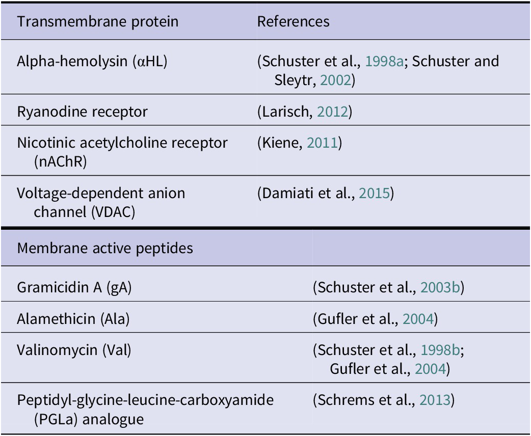
To sum up, the ability to act as biomimetic spacer and scaffold for composite lipid membranes maintaining ion channel activity make S-layer proteins attractive for biosensor applications. In this context, it should also be emphasized that S-layer stabilized solid supported functional lipid membranes with their nanopatterned fluidity have proven to be significantly superior in stability and shelf life to alternative strategies such as polymer cushions between the lipid membrane and the solid support (Györvary et al., Reference Györvary, Wetzer, Sleytr, Sinner, Offenhäuser and Knoll1999; Hirn et al., Reference Hirn, Schuster, Sleytr and Bayerl1999; Schuster et al., Reference Schuster, Sleytr, Diederich, Bahr and Winterhalter1999, Reference Schuster, Pum, Sára, Braha, Bayley and Sleytr2001; Schuster and Sleytr, Reference Schuster and Sleytr2000; Weygand et al., Reference Weygand, Schalke, Howes, Kjaer, Friedmann, Wetzer, Pum, Sleytr and Lösche2000; Sleytr et al., Reference Sleytr, Pum, Egelseer, Ilk, Schuster and Knoll2013). After all, we have only imitated one of nature’s inventions to keep archaeal lipid cell membranes functionally stable even under extreme environmental conditions. In the future, the ability to reconstitute integral membrane proteins in defined structures on, for example, sensor surfaces is one of the most important concerns in designing biomimetic sensing devices (Trojanowicz, Reference Trojanowicz2001; Sugawara and Hirano, Reference Sugawara, Hirano, Ottova and Tien2005; Tiefenauer and Demarche, Reference Tiefenauer and Demarche2012; Schuster, Reference Schuster2018).
An alternative strategy for the production of S-layer-stabilized lipid membranes has recently been presented, in which the functional membrane proteins embedded in the lipid matrix are modified using the QTY code strategy (Zhang et al., Reference Zhang, Tao, Qing, Tang, Skuhersky, Corin, Tegler, Wassie, Wassie, Kwon, Suter, Entzian, Schubert, Yang, Labahn, Kubicek and Maertens2018). For this, hydrophobic amino acids of the seven alpha helices of the membrane-integrated parts of the functional proteins are exchanged against hydrophilic ones in such a way that the membrane proteins become water-soluble (Zhang et al., Reference Zhang, Tao, Qing, Tang, Skuhersky, Corin, Tegler, Wassie, Wassie, Kwon, Suter, Entzian, Schubert, Yang, Labahn, Kubicek and Maertens2018; Tegler et al., Reference Tegler, Corin, Pick, Brookes, Skuhersky, Vogel and Zhang2020; Qing et al., Reference Qing, Hao, Smorodina, Jin, Zalevsky and Zhang2022, Reference Qing, Xue, Zhao, Wu, Breitwieser, Smorodina, Schubert, Azzellino, Jin, Kong, Palacios, Sleytr and Zhang2023). These modified (hydrophilized) proteins can subsequently be linked to carrier-bound functionalized S-layer lattices (Qing et al., Reference Qing, Xue, Zhao, Wu, Breitwieser, Smorodina, Schubert, Azzellino, Jin, Kong, Palacios, Sleytr and Zhang2023) in dense packing to obtain a highly specific sensor surface (see later).
Reassembly on liposomes, emulsomes and nanocapsules
Liposomes, emulsomes and nanocapsules serve as commonly employed model systems for investigating biological membranes and as delivery platforms for biologically active compounds (Schuster et al., Reference Schuster, Pum, Sára and Sleytr2006). Unilamellar liposomes are artificially prepared spherical containers consisting of a phospholipid bilayer shell and an aqueous core. Biologically active molecules like hydrophilic drugs can be stored and transported, whereas the lipidic shell can be loaded with hydrophobic drugs. Emulsomes, however, are spherical systems with a solid fat core surrounded by phospholipid mono- or multilayer(s). Emulsomes show a much higher loading capacity for lipophilic drug molecules like curcumin for targeted drug delivery against cancer and other diseases (Ücisik et al., Reference Ücisik, Küpcü, Debreczeny, Schuster and Sleytr2013a,Reference Ücisik, Küpcü, Schuster and Sleytrb, Reference Ücisik, Küpcü, Breitwieser, Gelbmann, Schuster and Sleytr2015a,Reference Ücisik, Sleytr and Schusterb). In addition, S-layer lattices as the envelope structure of the spherical containers represent biomimetic ‘artificial virus-like particles’, which enable both the stabilization of the nanocarriers and the presentation of the addressee molecules in a highly defined orientation and specific distribution. The orientation of the S-layer is dictated by the surface charge of the lipids or polyelectrolytes employed. Through extensive investigations utilizing S-layer-coated liposomes, we have demonstrated that the S-layer lattice enhances the stability of liposomes against mechanical stress (induced by shear forces or ultrasonication), thermal challenges and alterations in zeta potential (Küpcü et al., Reference Küpcü, Sára and Sleytr1995b). This finding supports the notion of the high stability of archaeal cell envelope structures. Moreover, to enhance the stability, the S-layer protein on the liposome can be cross-linked (Schuster et al., Reference Schuster, Pum, Sára and Sleytr2006). In addition, cross-linking can also be utilized for covalent attachment of biologically relevant macromolecules (Sleytr et al., Reference Sleytr, Sára, Pum, Schuster and Ciferri2005, Reference Sleytr, Huber, Ilk, Pum, Schuster and Egelseer2007b, Reference Sleytr, Egelseer, Ilk, Messner, Schäffer, Pum, Schuster, König, Claus and Varma2010, Reference Sleytr, Pum, Egelseer, Ilk, Schuster and Knoll2013). In turn, a layer of intact liposomes can also be reversibly tethered via the specific nickel–His-tag linkage on an S-layer lattice (Kepplinger et al., Reference Kepplinger, Ilk, Sleytr and Schuster2009).
Moreover, and most importantly, S-layer-coated liposomes constitute a versatile matrix for the covalent binding of macromolecules (Küpcü et al., Reference Küpcü, Sára and Sleytr1995b) (Figure 17).
S-layer-coated liposomes and emulsomes. (a) Schematic drawing of an S-layer-coated liposome (left) and emulsome (right) with bound functional molecules and functionalized by reconstituted integral proteins. S-layer-coated liposomes and emulsomes can be used as immobilization matrix for functional molecules either by direct binding or by genetically modified S-layer fusion proteins. (b) TEM micrograph of a freeze-etched preparation of an S-layer-coated liposome. (c) TEM micrograph of a negatively stained preparation of an S-layer-coated liposome coated completely with ferritin. (Reproduced from Küpcü et al., Reference Küpcü, Sára and Sleytr1995b, with permission.)

Biotinylation of S-layer-coated liposomes resulted in two accessible biotin residues per S-layer subunit for subsequent streptavidin binding (Mader et al., Reference Mader, Küpcü, Sleytr and Sára2000). By this approach, biotinylated ferritin and biotinylated anti-human immunoglobulin G (IgG) were attached via streptavidin to S-layer-coated liposomes. The biological activity of bound anti-human IgG was confirmed by ELISA (Mader et al., Reference Mader, Küpcü, Sleytr and Sára2000) and by measuring changes in ultrasound velocity (Krivanek et al., Reference Krivanek, Rybar, Küpcü, Sleytr and Hianik2002).
An interesting approach is the recrystallization of the S-layer-enhanced green fluorescent protein (EGFP) fusion protein on liposomes (Ilk et al., Reference Ilk, Küpcü, Moncayo, Klimt, Ecker, Hofer-Warbinek, Egelseer, Sleytr and Sára2004). By this means, the uptake via endocytosis of S-layer/EGFP fusion protein-coated liposomes into eukaryotic cells like HeLa cells could be visualized by the intrinsic EGFP fluorescence. The most interesting advantage can be seen in co-recrystallization of S-layer/EGFP and S-layer/streptavidin fusion proteins on the same liposome. The uptake of these specially coated liposomes by target cells and the functionality of transported drugs could be investigated simultaneously without the need of any additional labels.
Likewise on liposomes, several wildtype, recombinant and S-layer fusion proteins formed a closed S-layer lattice covering the entire surface of emulsomes composed of a solid tripalmitin core and a phospholipid shell (Ücisik et al., Reference Ücisik, Küpcü, Debreczeny, Schuster and Sleytr2013a). In vitro cell culture studies revealed that S-layer-coated emulsomes can be up taken by human liver carcinoma cells (HepG2) without showing any significant cytotoxicity. The utilization of S-layer fusion proteins equipped in a nanopatterned fashion by identical or diverse functions may lead to attractive nanobiotechnological and nanomedicinal applications, particularly as drug targeting and delivery systems, as artificial virus envelopes in, for example, medicinal applications and gene therapy (Mader et al., Reference Mader, Küpcü, Sleytr and Sára2000; Schuster and Sleytr, Reference Schuster and Sleytr2009; Ücisik et al., Reference Ücisik, Küpcü, Debreczeny, Schuster and Sleytr2013a). Finally, these biomimetic approaches are exciting examples for synthetic biology mimicking structural and functional aspects of many bacterial and archaeal cell envelopes having an S-layer lattice as outermost cell wall component (Sleytr et al., Reference Sleytr, Schuster, Egelseer and Pum2014).
At the end of this chapter, it is worth to mention that the S-layer liposome system also helped to address the binding properties of S-layers to the outer membrane of Gram-negative bacteria. As part of a joint project with John Smit during his sabbatical in 1997 at our institute, we were able to show that in analogy to the specific interaction between the S-layer subunits and the SCWP of the peptidoglycan-containing layer in Gram-positive organisms also in Gram-negative organisms a specific interaction must exists between the S-layer proteins and the lipopolysaccharides of the outer membrane. Recrystallization of the S-layer protein of Caulobacter crescentus on liposomes and Langmuir Blogett films only occurred when the lipid membranes contained the specific species of Caulobacter smooth lipopolysaccharides (Nomellini et al. Reference Nomellini, Kupcu, Sleytr and Smit1997). Thus, in both Gram-positive and Gram-negative organisms, the S-layer proteins do not only bind to their respective carrier layer (Figure 2d and 2e) in a defined orientation, but also have the ability for lateral mobility to assemble into a coherent low free energy arrangement.
Isoporous ultrafiltration membranes (molecular sieves, surface properties and antifouling)
When I (U.B.S.) was able to observe in 1966 for the first time in FE preparations that the cell surfaces of intact bacterial cells are covered with a coherent lattice structure, I realized that these outermost layers could represent a well-defined barrier which allows the passage of molecules such as nutrients, metabolic products and signalling molecules. It was also obvious that this outermost cell envelope structure must play a decisive role in the interaction of the cell with its environment and after I had examined various organisms with the help of FE, I realized that one of the most important general properties of the surface and pore area of S-layers appears to be their excellent antifouling behaviour. I found that cells harvested directly from very complex media, such as soils or culture media containing high-molecular components, even without a washing step, always showed the lattice structure very clearly (Figure 1). With the FE technique, specific or non-specific deposits could have been recognized very clearly by masking the lattice structures. Furthermore, the question arose whether the glycosylation of the S-layer enhances this effect (Schuster and Sleytr, Reference Schuster and Sleytr2015b). Thus, I concluded that an essential characteristic of S-layers is seen for maintaining an exchange of nutrients and metabolites between the cell and its environment (Sleytr et al., Reference Sleytr, Schuster, Egelseer and Pum2014). Furthermore, I was sure that the repetitive topographical structure of S-layers should be regarded as a significant characteristic affecting the hydrodynamic surface properties of bacterial cells. It was intriguing to suggest that the defined texture of S-layer surfaces dictates the flow resistance encountered by cells in their natural surroundings. About 50 years later, preliminary drag experiments were carried out with an optical trap, which indicated that micro metre-sized S-layer-coated microbeads have a slightly higher (if at all detectable) flow resistance compared to uncoated beads. We therefore decided to calculate the water flow through S-layers using computer simulations. We aimed to develop a theoretical model to gain deeper insights into the S-layer–water interface and in particular on the structure of the very first water layer next to the S-layer (Tscheliessnig et al., Reference Tscheliessnig, Breitwieser, Sleytr and Pum2021). Utilizing high-resolution cryo-TEM tomography data of the S-layer protein SbpA from L. sphaericus ATCC 4525 (also known as L. sphaercius CCM2177) as a model system (Comolli et al., Reference Comolli, Siegerist, Shin, Bertozzi, Regan, Zettl and De Yoreo2013), we computed the flow field of water, vorticity, electrostatic potential and electric field of a coarse-grained model of this S-layer. Our calculations revealed that both the inherent rigidity and charge distribution of the S-layer contribute to its rheological properties, as evidenced by local alterations in the flow profile. The presence of turbulence and pressure near the S-layer surface within the 10–50-nm range supported our hypothesis that the highly ordered repetitive crystalline structure of the S-layer not only enhances metabolite exchange rates but also accounts for its exceptional antifouling properties. The uptake of substances, including molecules and particles, within this size range is no longer constrained by diffusion. This research was reminiscent of the research conducted by E. M. Purcell more than 30 years ago in a ground-breaking lecture on life at low Reynolds numbers, particularly focusing on the locomotion of flagellum-driven bacterial cells (Purcell, Reference Purcell1977). Ultimately, the removal of molecules and particles results in a clean S-layer surface, justifying the considerable energy expenditure involved in its production within bacterial cells.
In this context, it should be considered that the S-layer in Gram-positive Bacteria also masks the net negative charge of the peptidoglycan layer, which significantly determines interactions between living cells and its environment. After demonstrating the existence of an S-layer protein pool in the peptidoglycan matrix in thin sections of intact cells, we suggested that the outer S-layer might represent the outer boundary of a kind of periplasmatic space in Gram-positive organisms and thus could be involved in the delay or controlled release of molecules such as exoenzymes (Graham et al., Reference Graham, Beveridge and Nanninga1991; Breitwieser et al., Reference Breitwieser, Gruber and Sleytr1992; Sturm et al., Reference Sturm, Egelseer, Sára, Sleytr, Beveridge and Koval1993).
Once data on the chemical structure of the S-layer proteins and high-resolution TEM images of negative-stained S-layer preparations were available, initial information on the pore structures in the lattice could be obtained in cooperation with Tony Crowther from MRC, Institute for Molecular Biology, Cambridge, UK by applying a newly developed imaging processing method (Crowther and Sleytr, Reference Crowther and Sleytr1977). In this publication describing the structure of a square (p4) and an hexagonal (p6) S-layer lattice from thermophilic Clostridia, we had already pointed out that interesting questions arise regarding the barrier function of the protein lattice to external factors, such as sensitivity to enzymes. Later I performed with M.S. permeability studies on S-layers from different Bacillaceae (Sára and Sleytr, Reference Sára and Sleytr1987b), applying the space technique (Scherrer and Gerhardt, Reference Scherrer and Gerhardt1971). For these permeability studies, we used S-layer containers composed of three adjacent layers, namely, the outer S-layer, the peptidoglycan-containing rigid layer and an inner S-layer attached to the inner face of the peptidoglycan layer (Figure 8). As described earlier, the inner S-layer was formed upon the removal of the plasma membrane out of the pool of S-layer subunits originally entrapped in the peptidoglycan layer (Breitwieser et al., Reference Breitwieser, Gruber and Sleytr1992). To distinguish between the molecular sieving properties between the S-layers and the peptidoglycan layer, we digested the peptidoglycan with lysozyme. The solutions selected for the molecular sieving measurements were sugars, proteins and dextran’s of increasing molecular weights (Figure 18).
Schematic drawing of the fine structure of S-layer ultrafiltration membranes. The active ultrafiltration layer consists of S-layer fragments deposited on (a) open-cell foam-like microfiltration membranes or (b) on the surface of nucleation-track membranes. (c) Rejection curve of S-layer ultrafiltration membranes. The isoporous S-layer fragments attached to the supporting microfiltration membrane (a and b) form the active ultrafiltration layer responsible for the sieving properties. Note the steep increase between molecular weights of 30,000 and 43,000 Da for S-layer fragments of G. stearothermophilus. (Modified and reproduced from Sleytr and Sára, Reference Sleytr, Sára, Küpcü and Messner1986b, with permission.)

We could demonstrate that the S-layer lattices allow free passage for molecules with a molecular weight of up to 30 kDa and revealed sharp exclusion limits between molecular weights of 30 and 45 kDa. These observations suggested a limiting pore diameter in the range of 3–4.5-nm, which correlate to the pore sizes determined with the aid of high-resolution TEM and AFM (Norville et al., Reference Norville, Kelly, Knight, Belcher and Walz2007; Messner et al., Reference Messner, Schäffer, Egelseer, Sleytr, König, Claus and Varma2010; Pavkov-Keller et al., Reference Pavkov-Keller, Howorka and Keller2011; Schuster and Sleytr, Reference Schuster and Sleytr2021). Most importantly, our permeability tests clearly showed that S-layer lattices are ultrafiltration membranes (UFMs) and that the supporting peptidoglycan matrix does not limit the passage of molecules capable of penetrating the S-layers. Moreover, the S-layer lattices in Bacillaceae do not act as effective barrier against lysozyme (Sára and Sleytr, Reference Sára and Sleytr1987b). But different to most UF membranes composed of polymer materials like polysulfone, polypropylene, cellulose acetate and polylactic acid (Fane et al., Reference Fane, Fell and Waters1981; Strathmann, Reference Strathmann1981; Pavanasam and Abbas, Reference Pavanasam and Abbas2008), which show a size distribution of the pores varying by up to an order of magnitude and a surface porosity usually lower than 10%, the S-layer UF membranes reveal pores of identical size and morphology and a porosity of up to 60%. But most importantly, since S-layers are composed of identical subunits, the functional groups on the surface and in the pores of the protein lattice are arranged in defined distribution and orientation. This means that the repetitive physicochemical properties of the S-layer UF membranes are also precisely determined down to the sub-nanometre range. The question that arose for us now was how we could produce a technologically relevant size from these UF membranes, which have been optimized by nature to the dimensions of a bacterial cell. Together with Margit Sára (M.S.) I tried a simple concept to solve this question. Our solution was based on the principle of roofing with shingles that overlap in position. We used both flat in vitro S-layer self-assembly products (Figure 4) and cell wall fragments in which the peptidoglycan layer was covered on both sides with a continuous S-layer (Figure 8). In analogy to the shingle-supporting grating on roofs, we have used for the deposition of the S-layer material microfiltration membranes (MFs) with open-cell foam-like substructures or radiation-track membranes with a pore size up to 1 μm (Figure 18).
After the S-layer preparations were deposited on the MFs during a filtration process under pressure as multilayer sediment, the protein lattices were subsequently intra- and intermolecular cross-linked with glutaraldehyde and Schiff bases reduced with borohydride (Sleytr and Sára, Reference Sleytr and Sára1986b, Reference Sleytr and Sára1988; Sára and Sleytr, Reference Sára and Sleytr1987c, Reference Sára, Sleytr and Rehm1988; Manigley et al., Reference Manigley, Wolf, Sára, Sleytr, Sleytr, Messner, Pum and Sàra1988; Sára et al., Reference Sára, Manigley, Wolf and Sleytr1988b,Reference Sára, Wolf, Sleytr, Sleytr, Messner, Pum and Sàrac, Reference Sára, Küpcü and Sleytr1990; Schuster and Sleytr, Reference Schuster and Sleytr2021). Most relevant such composite S-layer UF membranes revealed a remarkable chemical and thermal resistance comparable to polyamide membranes (Schuster and Sleytr, Reference Schuster and Sleytr2021).
After we had obtained these promising results from the preliminary tests, M.S. and I patented the technology and constructed a device with which SUMs in the dimensions of 30 cm × 60 cm could be produced semi-automatically (Sleytr and Sára, Reference Sleytr and Sára1988). These large-area membranes were later also used in crossflow and affinity modules (Sleytr and Sára, Reference Sleytr, Sára, Kula, Schügerl and Wandrey1986a; Sára et al., Reference Sára, Küpcü and Sleytr1990; Weiner et al., Reference Weiner, Sára, Dasgupta and Sleytr1994a,Reference Weiner, Sára and Sleytrb). Numerous studies on S-layer-ultrafiltration membranes (SUMs) showed that the pores of the constituent monomolecular S-layer lattice solely determined the cutoff since increasing thickness of the deposited, randomly arranged S-layer fragments did not change the nominal molecular weight cutoff values but only the flow rates for water or the test solutions (Schuster and Sleytr, Reference Schuster and Sleytr2021). It should also be mentioned that much later high-resolution electron microscopic investigations have demonstrated that more than one pore shape can exist in S-layer lattices (Norville et al., Reference Norville, Kelly, Knight, Belcher and Walz2007; Pavkov-Keller et al., Reference Pavkov-Keller, Howorka and Keller2011; Buhlheller et al., Reference Buhlheller, Sagmeister, Grininger, Gubensäk, Sleytr, Usón and Pavkov-Keller2024). In this case, however, it is always the largest pores that determine the cutoff, whereas the smaller pores only have an influence on flux of particle free water but not on the cutoff (Manigley et al., Reference Manigley, Wolf, Sára, Sleytr, Sleytr, Messner, Pum and Sàra1988; Sára and Sleytr, Reference Sára, Sleytr and Rehm1988; Sára et al., Reference Sára, Manigley, Wolf and Sleytr1988b,Reference Sára, Wolf, Sleytr, Sleytr, Messner, Pum and Sàrac, Reference Sára, Küpcü and Sleytr1990; Sleytr and Sára, Reference Sleytr and Sára1988; Sleytr et al., Reference Sleytr, Sára, Pum, Schuster and Rosoff2001b).
Since on S-layer lattices reactive groups (carboxyl, amino or hydroxyl groups) are located on each constituent protein subunit in an identical position and orientation, we could apply a broad spectrum of chemical modifications to obtain different charged or hydrophilic or hydrophobic UF membranes with defined nominal molecular mass cutoffs. For example, since cross-linking with glutaraldehyde involves the amino groups, carboxylic acid groups of the S-layer lattices were activated with 1-ethyl-3-(3-dimethylaminopropyl)carbodiimide (EDC) and allowed to react with the free amino groups from a broad spectrum of nucleophiles of different molecular size, structure, charge and hydrophobicity. For example, contact angle measurements demonstrated that covalent attachment of low molecular weight nucleophiles to the activated S-layer lattices led to SUMs with more hydrophilic or hydrophobic surface properties (Sára and Sleytr, Reference Sára and Sleytr1987c). Covalent attachment of low molecular weight nucleophile to SUMs not only led to alterations of the surface properties and antifouling characteristics but were also responsible for an accurate controlled shift of the rejection curves to the lower molecular weight range (Küpcü et al., Reference Küpcü, Sára and Sleytr1991, Reference Küpcü, Sára and Sleytr1993b; Pum and Sleytr, Reference Pum and Sleytr1995a; Sleytr et al., Reference Sleytr, Sára, Pum, Schuster and Rosoff2001b, Reference Sleytr, Sára, Pum, Schuster and Ciferri2005, Reference Sleytr, Schuster, Egelseer, Pum, Horejs, Tscheliessnig and Ilk2011) (Table 3). The latter was explained by the fact that molecules were bound in the pore area. By using SUMs with defined pore sizes and physicochemical surface properties, it was thus possible for the first time to determine correlations between the pore size and the net charge of an ultrafiltration layer, and the flux losses determined by adsorption of proteins with defined molecular characteristics (dimension, charge, hydrophobicity and hydrophilicity) at the surface. This experimental approach is considered crucial for the development of various UFMs with tailored molecular sieving and antifouling characteristics for very specific requirements (Sára and Sleytr, Reference Sára and Sleytr1987c; 1987b; Weigert and Sára, Reference Weigert and Sára1996; Schuster and Sleytr, Reference Schuster and Sleytr2021). Due to the numerous atomic models of S-layers that were becoming available, it was even possible to precisely track the passage of molecules through the pores during the filtration process (Sotiropoulou et al., Reference Sotiropoulou, Mark, Angert and Batt2007). Previous filtration experiments have already shown that elongated molecules can only pass through the SUMs in a specific orientation. Most recently, AlphaFold (Jumper et al., Reference Jumper, Evans, Pritzel, Green, Figurnov, Ronneberger, Tunyasuvunakool, Bates, Žídek, Potapenko, Bridgland, Meyer, Kohl, Ballard, Cowie, Romera-Paredes, Nikolov, Jain, Adler, Back, Petersen, Reiman, Clancy, Zielinski, Steinegger, Pacholska, Berghammer, Bodenstein, Silver, Vinyals, Senior, Kavukcuoglu, Kohli and Hassabis2021; Buhlheller et al., Reference Buhlheller, Sagmeister, Grininger, Gubensäk, Sleytr, Usón and Pavkov-Keller2024) was used to show that S-layers of Archaea can have pore sizes of up to 8 nm. This should in principle make it possible to produce isoporous ultra filtration membranes for a wider range of applications (Pfeifer et al., Reference Pfeifer, Ehmoser, Rittmann, Schleper, Pum, Sleytr and Schuster2022). However, Margit Sara and I soon realized that the decisive factor in the commercial implementation of inventions is not only technological superiority alone, but competition with methods that have been established over the long term. For example, although SUMs are far superior to conventional polysulfone dialysis membranes due to their permeability and anti-fouling properties, it was not possible to achieve an exchange of technologies. Nevertheless, from a historical point of view, SUMs were the first nano-biotechnology products based on S-layers (Sleytr and Sára, Reference Sleytr and Sára1988).
Rejection characteristics of SUMs prepared of S-layers from G. stearothermophilus strains
The rejection coefficient (R) was calculated according to the following equation: R=ln(Cr/Co)/ln(Vo/Vr). Cr or Vr, represent the protein concentration in the retentate or the volume of the retentate; Co is the concentration of the protein in the solution before filtration; Vo is the initial volume of the feed. The pH value of each protein solution was immediately measured after dissolving the protein in distilled water (modified after (Schuster and Sleytr Reference Schuster and Sleytr2021))
S-Layers as matrix for functional molecules and nanoparticles
Our work on the production and chemical modification of S-layer ultrafiltration membranes (SUMs) has also led us to the use of S-layers as an immobilization matrix for functional molecules and nanoparticles. The high density of functional groups that are in well-defined positions on the surface and the pore areas of S-layer lattices and their accessibility for chemical modifications made S-layers to excellent patterning elements for a defined attachment of functional molecules and nanoparticles. I (U.B.S.) came up with the idea for this application potential from labelling the negatively charged domains on S-layer lattices using PCF as a topographic marker. This showed for the first time that the binding pattern of an approximately 11-nm large PCF molecule, due to electrostatic interactions, corresponded exactly to the S-layer lattice used (Sleytr, Reference Sleytr and Kiermayer1981; Messner et al., Reference Messner, Pum, Sára, Stetter and Sleytr1986a,Reference Messner, Pum and Sleytrb; Sára and Sleytr, Reference Sára and Sleytr1996). Subsequently, this immobilization principle was used together with D.P. and M.S. for a wide range of applications including the immobilization of functional (macro) molecules (e.g., ligands, antigens, monoclonal antibodies and enzymes). For this purpose, the free carboxylic acid groups originating from glutamic or aspartic acid in the S-layer protein were activated with carbodiimide and subsequently reacted with free amino groups of functional macro molecules, leading to stable peptide bonds (Sára and Sleytr, Reference Sára and Sleytr1989; Küpcü et al., Reference Küpcü, Neubauer, Hödl, Pum, Sára, Sleytr, Guilbault and Mascini1993a;Weiner et al., Reference Weiner, Sára, Dasgupta and Sleytr1994a, Reference Weiner, Sára and Sleytr1994b). In addition, sulphhydryl groups were also introduced into S-layer lattices as an alternative immobilization option via disulphide bridges (Sára and Sleytr, Reference Sára and Sleytr1992). In a different approach, functionalized S-layer lattices formed by S-layer fusion protein rSbpA/STII/Cys exhibiting highly accessible cysteine residues in a well-defined arrangement on the surface could be utilized for the template-assisted patterning of gold nanoparticles (Badelt-Lichtblau et al., Reference Badelt-Lichtblau, Kainz, Vollenkle, Egelseer, Sleytr, Pum and Ilk2009).
In the case of glycosylated S-layers, immobilization methods were used in which the carbohydrate portion was used as a binding site (Sára et al., Reference Sára, Küpcü and Sleytr1989; Messner et al., Reference Messner, Küpcü, Sára, Pum, Sleytr and Conradt1991, Reference Messner, Mazid, Unger and Sleytr1992b). In conjunction with the labelling experiments of the carbohydrate chains of glycosylated S-layers, we were able to show in previous studies that with the help of cyanogen bromide vicinal hydroxyl groups of the carbohydrate chains could be activated, which could then react with the amino groups of amino carbonic acids of functional proteins. When, for example, ferritin molecules as topographical markers were offered as binding partners, an immobilization pattern arose that corresponded exactly to the underlying S-layer glycoprotein lattice (Sára et al., Reference Sára, Küpcü and Sleytr1989). However, these methods never produced the exact molecular binding observed with direct coupling via peptide bonds. Much later we were able to show that by genetic engineering techniques, specific functional domains can be incorporated in S-layer proteins while maintaining the self-assembly capability (Ilk et al., Reference Ilk, Egelseer and Sleytr2011a). These techniques have led to new types of affinity structures, microcarrier, enzyme membranes, diagnostic devices, biosensors, vaccines and drug targeting and delivery systems (Sleytr et al., Reference Sleytr, Egelseer, Ilk, Messner, Schäffer, Pum, Schuster, König, Claus and Varma2010, Reference Sleytr, Schuster, Egelseer and Pum2014; Ilk et al., Reference Ilk, Egelseer and Sleytr2011a).
Independent of the type of S-layer protein originating from different Bacillacae, large enzymes such as invertase, glucose oxidase, glucuronidase or beta-galactosidase formed a monolayer on the outer surface (Neubauer et al., Reference Neubauer, Pum and Sleytr1993, Reference Neubauer, Hödl, Pum and Sleytr1994, Reference Neubauer, Pum, Sleytr, Klimant and Wolfbeis1996; Sára et al., Reference Sára, Küpcü, Sleytr, Sleytr, Messner, Pum and Sára1996b; Sleytr et al., Reference Sleytr, Sára, Pum, Schuster and Rosoff2001b). The activity of small enzymes retained upon immobilization strongly depended on the molecular size of the enzyme, the morphological properties of the S-layer lattice and the applied immobilization procedure (Küpcü et al., Reference Küpcü, Mader and Sára1995a).
Biosensors based on S-layer technology
S-layers have been used as immobilization matrices for a wide range of macromolecules in the development of amperometric, optical, acoustic (mass sensitive) and electronic biosensors. Moreover, in most cases, the platforms were regeneratable and thus device reuse and functional tuning possible (see, for a review, Schuster, Reference Schuster2018; Damiati and Schuster, Reference Damiati and Schuster2020; Sleytr et al., Reference Sleytr, Sára, Pum and Schuster2001, Reference Sleytr, Sára, Pum, Schuster and Ciferri2005).
For the production of individual biosensors, such as the glucose sensor, glucose oxidase was covalently bound to the outer S-layer surface of SUMs and retained approximately 40% of its activity. The electrical contact to the sensor layer was established by sputtering a thin layer of platinum or gold onto the enzyme layer. The analyte reached the sensor layer, consisting of the enzyme layer and the S-layer, through the highly porous microfiltration layer from the opposite side. During the enzymatic reaction, gluconic acid and hydrogen peroxide are produced under consumption of oxygen. The glucose concentration was then determined by measuring the electrical current during the electrochemical oxidation of the produced hydrogen peroxide (Neubauer et al., Reference Neubauer, Pum and Sleytr1993). These sensors yielded high signals (150 nA/mm2/mmol glucose), fast response times (10–30s) and a linearity range up to 12-mM glucose. The stability under working conditions was more than 48 hours, and there was no loss in activity after a storage period of 6 months.
A different design principle had to be developed for multi-enzyme biosensors in order to be able to precisely adjust the quantities of the individual enzymes in the sensor layer. Here, each enzyme species was individually bound to samples of S-layer fragments. The various enzyme-loaded S-layer-carrying cell wall fragments were then mixed in suspension, deposited onto the MF and sputter-coated with platinum or gold. In this way, the amount of the various enzymes could be considered depending on their retained activity in the course of immobilization. Based on this technique, several multi-enzyme sensors were developed, such as a sucrose sensor consisting of the three enzymes invertase, mutarotase and glucose oxidase or a cholesterol sensor with cholesterol esterase and cholesterol oxidase (Neubauer et al., Reference Neubauer, Hödl, Pum and Sleytr1994). In addition, this approach also allowed the integration of charged or uncharged barrier layers into the biosensor architecture. Nevertheless, the enzyme activity suffers in the vacuum upon the sputter coating process. This drawback could be circumvented by pulsed-laser-deposition of the metals (Neubauer et al., Reference Neubauer, Pentzien, Reetz, Kautek, Pum and Sleytr1997). The latter approach resulted in an enzyme activity of 70%–80%, which was a doubling of the activity compared to the sputter coating approach.
Later, sensor layers based on S-layers as molecular patterning elements were also used in the development of optical biosensors (opt(r)odes), in which the amperometric detection principle was replaced by an optical one (Neubauer et al., Reference Neubauer, Pum, Sleytr, Klimant and Wolfbeis1996; Scheicher et al., Reference Scheicher, Kainz, Kostler, Suppan, Bizzarri, Pum, Sleytr and Ribitsch2009). In the first approach, a 5-μm-thick polymeric membrane, in which an oxygen-sensitive fluorescent dye (ruthenium(II) complex) was immersed, was brought in direct contact with a monolayer of glucose oxidase immobilized on SUM in the same way as described before. The fluorescence of the Ru(II) complex is dynamically quenched by molecular oxygen, so that a decrease in the local oxygen concentration led to a measurable signal (Neubauer et al., Reference Neubauer, Pum, Sleytr, Klimant and Wolfbeis1996). In a further approach, an oxygen sensor was developed in which an oxygen sensitive Pt(II) porphyrin dye was covalently bound to the S-layer (Scheicher et al., Reference Scheicher, Kainz, Kostler, Suppan, Bizzarri, Pum, Sleytr and Ribitsch2009). Variations in the oxygen concentration resulted in distinct and reproducible changes in luminescence lifetime and intensity. It has to be stressed here that in both approaches low-cost optoelectronic components were used. A decade later, the use of S-layers as a versatile immobilisation layer was taken up again in the development of DNA microarrays (Scheicher et al., Reference Scheicher, Kainz, Kostler, Reitinger, Steiner, Ditlbacher, Leitner, Pum, Sleytr and Ribitsch2013). Various fluorescently labelled, amino-functionalized DNA oligomers were covalently bound to the S-layer. The hybridization and dissociation of the DNA oligomers was investigated and evaluated using a compact, low-cost platform for direct fluorescence imaging based on surface plasmon enhanced fluorescence excitation.
Moreover, an SbpA S-layer lattice was conjugated with folate and recrystallized on a gold surface (Damiati et al., Reference Damiati, Peacock, Mhanna, Sopstad, Sleytr and Schuster2018). This biorecognition layer ensured the specific capture of human breast adenocarcinoma cells (MCF-7) via the recognition of folate receptors.
Most recently, a biomimetic platform was presented that combined a ‘dual-monolayer’ biorecognition construct with hundreds of graphene-based field-effect-transistor arrays (Qing et al., Reference Qing, Xue, Zhao, Wu, Breitwieser, Smorodina, Schubert, Azzellino, Jin, Kong, Palacios, Sleytr and Zhang2023). The construct adopted redesigned water-soluble membrane receptors as specific sensing units, positioned and oriented by S-layer proteins. The functionality was demonstrated with an rSbpA-ZZ/CXCR4(QTY)-Fc combination. Nature-like specific interactions were achieved towards an immune molecule called CXCL12 and HIV coat glycoprotein in physiologically relevant concentrations without notable sensitivity loss in 100% human serum. It has to be stressed again that the device detects the same molecules that cell receptors do, and may enable routine early screening for cancers and other diseases. The key was a novel way to transform hydrophobic proteins into water-soluble proteins, by swapping out a few hydrophobic amino acids for hydrophilic amino acids (Zhang et al., Reference Zhang, Tao, Qing, Tang, Skuhersky, Corin, Tegler, Wassie, Wassie, Kwon, Suter, Entzian, Schubert, Yang, Labahn, Kubicek and Maertens2018; Tegler et al., Reference Tegler, Corin, Pick, Brookes, Skuhersky, Vogel and Zhang2020; Qing et al., Reference Qing, Hao, Smorodina, Jin, Zalevsky and Zhang2022, Reference Qing, Xue, Zhao, Wu, Breitwieser, Smorodina, Schubert, Azzellino, Jin, Kong, Palacios, Sleytr and Zhang2023). This approach is called the QTY code after the letters representing the three hydrophilic amino acids – glutamine, threonine and tyrosine – that take place of hydrophobic amino acids leucine, isoleucine, valine and phenylalanine (Zhang et al., Reference Zhang, Tao, Qing, Tang, Skuhersky, Corin, Tegler, Wassie, Wassie, Kwon, Suter, Entzian, Schubert, Yang, Labahn, Kubicek and Maertens2018, Reference Zhang, Qing, Breitwieser and Sleytr2022, Reference Zhang, Jin, Qing and Sleytr2024).
Within the context of biosensing, we would also like to mention our successful work to develop a key enabling technology for the fabrication of nano patterned thin film imprints by using functional S-layer protein arrays as templates (Ladenhauf et al., Reference Ladenhauf, Pum, Wastl, Toca-Herrera, Phan, Lieberzeit and Sleytr2015; Phan et al., Reference Phan, Sussitz, Ladenhauf, Pum and Lieberzeit2018). Due to the crystalline character of the S-layer template, the unique feature of such novel imprints was the precisely controlled repetition of surface functional groups and domains, and topographical features.
In this context of the development of biosensing surfaces where S-layers play a critical role, the anisotropy between the inner and outer faces of the S-layer protein SbpA was used to develop a novel, tuneable, facile and reliable method for cellular micropatterning (Picher et al., Reference Picher, Küpcü, Huang, Dostalek, Pum, Sleytr and Ertl2013; Rothbauer et al., Reference Rothbauer, Küpcü, Sticker, Sleytr and Ertl2013, Reference Rothbauer, Ertl, Theiler, Schlager, Sleytr and Küpcü2015). By simply altering the recrystallization protocol from basic (pH 9) to acidic (pH 4) conditions, the SbpA S-layer orientation was adjusted to effectively prevent protein adsorption and cell adhesion (smooth outer cytophobic side exposed), or, alternatively, to promote cell attachment and spreading (rough inner cytophilic side exposed).
In summary, it is the versatility that makes S-layer-based biosensors suitable for a wide range of applications, including medical diagnostics, food safety monitoring and environmental monitoring.
S-layers as matrix for solid-phase immunoassays and affinity microparticles
At the same time as working on the development of S-layer-based biosensors, we have also been working on the functionalization of S-layers with various ligands and immunoglobulins. The most detailed investigations were carried out with protein A (Mr 42,000) a ligand originally isolated from the cell wall of Staphylococcus aureus, which recognizes the Fc part of most mammalian antibodies leading to an oriented binding of Immunoglobulins. In order to functionalize S-layer lattices, either protein A was directly linked to the EDC-activated carboxylic acid groups of the S-layer protein from Th. thermohydrosulfuricum L111-69 and L. sphaericus CCM 2120, or it was immobilized via spacer molecules (Weiner et al., Reference Weiner, Sára and Sleytr1994b; Breitwieser et al., Reference Breitwieser, Küpcü, Howorka, Weigert, Langer, Hoffmann-Sommergruber, Scheiner, Sleytr and Sára1996). Calculations on the binding density provided evidence that the extremely long protein A molecules were immobilized in an oriented manner, with their long axis perpendicular to the S-layer lattice.
In another approach for preparing S-layer affinity matrices, we immobilized streptavidin (Mr 66,000), which is a tetramer, and each subunit has one binding site for biotin (Weiner et al., Reference Weiner, Sára and Sleytr1994b; Breitwieser et al., Reference Breitwieser, Küpcü, Howorka, Weigert, Langer, Hoffmann-Sommergruber, Scheiner, Sleytr and Sára1996). Since well-established protocols are available for biotinylating of any type of substance and the biotin–streptavidin bonds are among the strongest non-covalent bonds known in nature, we considered this system to be particularly attractive for functionalizing solid supports. Since covalent binding of streptavidin to S-layer lattices via EDC-activated carboxylic acid groups did not lead to a monolayer of densely packed molecules, the S-layer protein from L. sphaericus CCM2120 was first modified with EDC/ethylendiamine and introduced amino groups were subsequently exploited for binding of sulfo N-hydroxysuccinimide biotin. After incubation with streptavidin, such modified S-layer lattices could bind 800 ng/cm2, which corresponded to a monolayer of densely packed molecules of the ligand (Breitwieser et al., Reference Breitwieser, Küpcü, Howorka, Weigert, Langer, Hoffmann-Sommergruber, Scheiner, Sleytr and Sára1996). Both S-layer affinity matrices obtained by binding protein A or streptavidin were exploited for immobilization of native or biotinylated human IgG as required for affinity microparticles (AMPs) and matrices for dipstick-style solid-phase immunoassays.
AMPs were obtained by cross-linking the S-layer lattice on S-layer-carrying cell wall fragments with glutaraldehyde, reducing Schiff bases with sodium borohydride, and immobilizing protein A as an IgG-specific ligand (Weiner et al., Reference Weiner, Sára, Dasgupta and Sleytr1994a). These cell wall fragments had a cup-shaped structure, in the form of broken up rod-shaped cells with an identical oriented outer and inner S-layer lattice on both surfaces of the peptidoglycan-containing layer available for immobilization of the ligand (Figure 8). Both the shape of the AMPs and the presence of two identically oriented S-layer lattices endowed the particles with an extremely high surface-to-volume ratio, which made them excellent escort particles in affinity crossflow filtration (Weiner et al., Reference Weiner, Sára, Dasgupta and Sleytr1994a,Reference Weiner, Sára and Sleytrb). In contrast to many particles proved for their applicability as escort particles in affinity cross-flow filtration, AMPs showed a high stability towards shear forces and revealed no leakage of the covalently bound ligand. Due to these features, AMPs were used for the isolation of human IgG from human IgG–human serum albumin mixtures, from serum, or from hybridoma cell culture supernatants (Weiner et al., Reference Weiner, Sára and Sleytr1994b) and as novel immunosorbent particles in blood purification (Weiner et al., Reference Weiner, Sára and Sleytr1994b; Weber et al., Reference Weber, Weigert, Sára, Sleytr and Falkenhagen2001; Völlenkle et al., Reference Völlenkle, Weigert, Ilk, Egelseer, Weber, Loth, Falkenhagen, Sleytr and Sára2004).
SUMs produced from S-layer carrying cell wall fragments from L. sphaericus CCM2120 were also used as a novel immobilization matrix in the development of dipstick-style solid-phase immunoassays (Breitwieser et al., Reference Breitwieser, Mader, Schocher, Hoffmann-Sommergruber, Aberer, Scheiner, Sleytr and Sára1998). The specific advantage of SUMs as immobilization matrix in comparison to other polymers can be seen in the presence of a dense monolayer of covalently bound antibodies (catching antibodies) on the surface of the S-layer lattice, which prevents nonspecific adsorption and diffusion-limited reactions (Breitwieser et al., Reference Breitwieser, Mader, Schocher, Hoffmann-Sommergruber, Aberer, Scheiner, Sleytr and Sára1998). The suitability of SUMs as matrix for immunoassays was demonstrated with following dipsticks: (i) for diagnosis of type I allergies (determination of IgE in whole blood or serum against the major birch pollen allergen Bet v1; (ii) for the quantification of tissue-type plasminogen activator (t-PA) in patients’ whole blood or plasma for monitoring t-PA levels in the course of thrombolytic therapy after myocardial infarcts and (iii) for the determination of interleukins in whole blood or serum to clarify whether intensive care patients suffer under traumatic or septic shock (Sleytr et al., Reference Sleytr, Sára, Pum, Schuster and Rosoff2001b) (Box 5).
Advantages in using S-layers as immobilization matrix for solid-phase immunoassays.
Accumulated data confirmed that the advantages of S-layers as immobilization matrix and especially as reaction zone for solid-phase immunoassays can be summarized as follows:
-
I. S-layers protein or glycoprotein lattices have repetitive functional groups down to the sub-nanometre scale.
-
II. Because of the molecular size of the catching antibody, immobilization can occur only on the outermost S-layer surface, thereby preventing diffusion-limited reactions during further incubation and binding steps.
-
III. Since the catching antibody is covalently linked to the S-layer lattice, no leakage problems arise during the test procedure
-
IV. S-layers do not unspecifically adsorb plasma or serum components, which make blocking steps as required for immunoassays with conventional matrices unnecessary.
-
V. Stable, concentration-dependent precipitates are formed on the S-layer surface by using appropriate substrates for peroxidase- or alkaline phosphatase-conjugated antibodies in the final detection step (Sleytr et al., Reference Sleytr, Sára, Pum, Schuster, Messner, Schäffer, Steinbüchel and and Fahnestock2002).
Binding of preformed nanoparticles
Based on our work on biomolecule binding, it was evident that S-layers could also be used to create highly ordered arrays of preformed metallic or semiconducting nanoparticles (Györvary et al., Reference Györvary, Schroedter, Talapin, Weller, Pum and Sleytr2004). This is because in S-layers the properties of a single constituent unit, replicated with the periodicity of the lattice, determine the characteristics of the overall two-dimensional array. As already mentioned, the pattern of bound molecules and nanoparticles corresponds to the lattice symmetry, the size of the morphological units and the surface chemical properties. The specific binding of nanoparticles was triggered by various non-covalent forces, such as electrostatic forces. Most important in this respect was the labelling of negatively charged domains on S-layers with PCF (diameter 12 nm) as already explained before. The regular arrangement of the free carboxylic acid groups on the hexagonal S-layer of T. tenax could be clearly demonstrated in this way (Messner et al., Reference Messner, Pum, Sára, Stetter and Sleytr1986a) (Figure 11). Later, 5-nm-sized citrate-stabilized gold and 4-nm amino-functionalized CdSe nanoparticles were bound to S-layer protein monolayers and self-assembly products of SbpA, the S-layer protein of L. sphaericus CCM2177 (Györvary et al., Reference Györvary, Schroedter, Talapin, Weller, Pum and Sleytr2004). At the same time, other groups have demonstrated the binding of 5- and 8-nm negatively charged gold nanoparticles on the hexagonally packed interlayer of the S-layer of Deinococcus radiodurans (Hall et al., Reference Hall, Shenton, Engelhardt and Mann2001 ; Bergkvist et al., Reference Bergkvist, Mark, Yang, Angert and Batt2004).
However, the major breakthrough in the controlled binding of molecules and nanoparticles was achieved by the successful development and expression of streptavidin S-layer fusion proteins, which enabled specific binding of up to three biotinylated ferritin molecules per S-layer subunit in a highly defined orientation and position ordered in large-scale arrays (Moll et al., Reference Moll, Huber, Schlegel, Pum, Sleytr and Sára2002). This approach will be described later in detail in this review.
Wet chemical synthesis of nanoparticles – biomineralization
In the early 1990s, Terry J. Beveridge and colleagues from the University of Guelph, Canada, pointed out the importance of S-layers in bacterial mineral formation in natural environments (Douglas and Beveridge, Reference Douglas and Beveridge1998). Building on these findings, in collaboration with Steven Mann from the University of Bath, UK (later University of Bristol, UK), we were the first to investigate a wet-chemical method for the precipitation of metal ions on S-layers (Shenton et al., Reference Shenton, Pum, Sleytr and Mann1997). In this method, self-assembled S-layer structures are exposed to a metal salt solution, followed by a slow reaction with a reducing agent such as hydrogen sulphide (H2S). Superlattices of nanoparticles were then formed based on the lattice spacing and symmetry of the underlying S-layer. As the metal precipitation took place in the pores of the S-layer, the resulting nanoparticles partially reflected the morphology of these pores (Dieluweit et al., Reference Dieluweit, Pum and Sleytr1998). The first application of this technique involved the precipitation of cadmium sulphide (CdS) on S-layer lattices from G. stearothermophilus NRS 2004/3a variant 1, and the S-layer protein SbpA of L. sphaericus CCM2177. After the incubation of S-layer self-assembly products with a CdCl2 solution for several hours, the hydrated samples were exposed to H2S for at least 1–2 days. The generated CdS nanoparticles were 4–5 nm in size, and their superlattices resembled the oblique lattice symmetry of G. stearothermophilus NRS 2004/3a variant 1, or the square lattice symmetry of SbpA, respectively. Soon later, a superlattice of 4–5-nm-sized gold nanoparticles was formed by using SbpA (with previously induced thiol groups) as template for the precipitation of a tetrachloroauric (III) acid (HAuCl4) solution (Dieluweit et al., Reference Dieluweit, Pum and Sleytr1998). Gold nanoparticles were formed either by the reduction of the metal salt with H2S or under the electron beam in a transmission electron microscope (Dieluweit et al., Reference Dieluweit, Pum and Sleytr1998; Mertig et al., Reference Mertig, Wahl, Lehmann, Simon and Pompe2001; Wahl et al., Reference Wahl, Mertig, Raff, Selenska-Pobell and Pompe2001). The later approach was technologically highly interesting because it allowed the definition of areas in which nanoparticles are eventually formed. Characterization by electron diffraction revealed that the gold nanoparticles were crystalline but did not exhibit crystallographic alignment across the superlattice (Figure 19). Subsequent analyses using X-ray photoelectron emission spectroscopy confirmed the elemental composition of the gold nanoparticles (Dieluweit et al., Reference Dieluweit, Pum, Sleytr and Kautek2005).
TEM micrographs of the chemically modified and gold(III)chloride treated S-layer lattice of L. sphaericus CCM2177 under increasing electron doses. (a) A coherent film of fine grainy gold precipitates is found under low electron dose conditions. (b, c) Upon increase of the electron dose, regularly arranged monodisperse gold clusters are formed in the pore region of the S-layer. The gold clusters resemble the square morphology of the S-layer pores. (Reproduced from Dieluweit et al., Reference Dieluweit, Pum and Sleytr1998, with permission).

A few years later, we took up this topic again in studying the S-layer-templated bioinspired synthesis of silica (Göbel et al., Reference Göbel, Schuster, Baurecht, Sleytr and Pum2010; Schuster et al., Reference Schuster, Küpcü, Belton, Perry, Stoger-Pollach, Sleytr and Pum2013). First, silica layers on S-layer self-assembly products were formed using tetramethoxysilane (TMOS) and visualized by TEM. In situ quartz crystal microbalance with dissipation monitoring (QCM-D) measurements showed the adsorption of silica in dependence on the presence of phosphate in the silicate solution and on the preceding chemical modification of the S-layer with EDC hydrochloride. Fourier transform infrared attenuated total reflectance spectroscopy revealed the formation of an amorphous silica gel (4–21 monolayers of SiO2) on the S-layer. In the following, we were able to show that it is possible to silicify S-layer-coated liposomes and to obtain stable functionalized hollow nano-containers. For this purpose, the S-layer protein of G. stearothermophilus PV72/p2 was recombinantly expressed and used for coating positively charged liposomes composed of DPPC, cholesterol and hexadecylamine in a molar ratio of 10:5:4. Subsequently, plain (uncoated) liposomes and S-layer-coated liposomes were silicified using tetraethyl orthosilicate. The determination of the charge of the constructs during silicification allowed the deposition process to be followed. After the liposomes had been silicified, lipids were dissolved by treatment with Triton X-100. The release of previously entrapped fluorescent dyes through the pores in the S-layer was determined by fluorimetry. Energy filtered TEM confirmed the successful construction of S-layer-based silica cages (Schuster et al., Reference Schuster, Küpcü, Belton, Perry, Stoger-Pollach, Sleytr and Pum2013). The thickness of the silica layer was in the range of 3.5–7 nm but was unevenly distributed. Most recently, we proposed a new methodology for making biogenic silica nanotubes based on S-layers. Multi-walled S-layer-coated CNTs were silicified with TMOS in a mild biogenic approach (Breitwieser et al., Reference Breitwieser, Sleytr and Pum2021). As expected, the thickness of the silica layer could be controlled by the reaction time and was approximately 6.3 nm after 5 minutes and 25.0 nm after 15 minutes. It is worth noting that the silica thickness after 5 minutes silicification time is close to the thickness of the S-layer and might resemble the porous S-layer ultrastructure similar to silicified S-layer liposomes. It is very likely that very thin silica coatings on CNTs will find new applications as novel nanocontainers (Fiegel et al., Reference Fiegel, Harlepp, Begin-Colin, Bégin and Mertz2024).
In addition, it has to be stressed here that starting in the late 1990ies, very detailed investigations about the wet chemical synthesis of metal nanoparticles on S-layers were carried out in the group of Wolfgang Pompe and Michael Mertig in Dresden, Germany, too (see the following references, just to name a few, Mertig et al., Reference Mertig, Kirsch, Pompe and Engelhardt1999, Reference Mertig, Wahl, Lehmann, Simon and Pompe2001; Pompe et al., Reference Pompe, Mertig, Kirsch, Wahl, Ciacchi, Richter, Seidel and Vinzelberg1999; Wahl et al., Reference Wahl, Engelhardt, Pompe and Mertig2005; Queitsch et al., Reference Queitsch, Mohn, Schaffel, Schultz, Rellinghaus, Bluher and Mertig2007). The S-layers of Sporosarcina ureae or Bacillus sphaericus NCTC 9602, both exhibiting square (p4) lattice symmetry, were used as template for the cluster deposition of platinum or palladium salts by chemical reduction or by irradiation with an electron beam in a TEM. UV–VIS spectrometry was used to follow the growth kinetics and TEM to image the well-separated metal clusters in or at the nano-sized pores of the S-layer. In addition, this group investigated the electronic structure of S-layers for applications in molecular electronics too (Vyalikh et al., Reference Vyalikh, Danzenbacher, Mertig, Kirchner, Pompe, Dedkov and Molodtsov2004, Reference Vyalikh, Kummer, Kade, Bluher, Katzschner, Mertig and Molodtsov2009).
Another current approach considers the use of bacterial S-layers as a potential alternative for bioremediation processes of heavy metals in the field. The S-layer of B. sphaericus JG-A12, an isolate from a uranium mining waste pile in Germany, was shown to bind high amounts of toxic metals such as U, Cu, Pd(II), Pt(II) and Au(III) (Pollmann et al., Reference Pollmann, Raff, Merroun, Fahmy and Selenska-Pobell2006; Suhr et al., Reference Suhr, Unger, Viacava, Gunther, Raff and Pollmann2014) or cadmium from contaminated water samples (Patel et al., Reference Patel, Zhang, McKay, Vincent and Xu2010). These special capabilities of the S-layers are highly interesting for the clean-up of contaminated waste waters and in particular for the recovery of precious metals from wastes of the electronic industry.
Although native S-layers have clearly demonstrated the presence and availability of functional sites for the precipitation of metal ions, a much more controlled and specific way of making highly ordered nanoparticle arrays uses genetic approaches for the construction of chimeric S-layer fusion proteins incorporating unique polypeptides that have been demonstrated to be responsible for biomineralization processes (Naik et al., Reference Naik, Stringer, Agarwal, Jones and Stone2002, Reference Naik, Jones, Murray, McAuliffe, Vaia and Stone2004). The precipitation of metal ions or binding of metal nanoparticles is then confined to specific and precisely localized positions in the S-layer lattice (unpublished results).
S-Layer fusion proteins: a synthetic biology approach
The demonstrated suitability of native S-layers as a matrix for the immobilization of functional molecules gave M.S. and me (U.B.S.) the idea of trying to fuse functional proteins directly with S-layer proteins. We assumed that the production of such chimeric S-layer fusion proteins would allow a defined positioning and spatial arrangement of the functional domains in the nanometre range solely determined by the selected S-layer lattice type and the lattice constant. The cartoon illustrates the principle of S-layer fusion proteins we had in mind using the example of a chessboard with pieces (horses) (Figure 20) (see also Box 6 and 7).
The use of S-layer fusion proteins has the following advantages over less nanostructured approaches.
-
I. The requirement of only a simple, one-step incubation process for site-directed immobilization without preceding surface activation of the support.
-
II. The general applicability of the ‘S-layer tag’ to any fusion partner.
-
III. The high flexibility for the variation of the functional group within a single S-layer lattice by co-crystallization of different S-layer fusion proteins to construct multifunctional array.
-
IV. If the size of the functional fusion partner exceeds the size of the constituent S-layer subunit, sufficient space can be created on the surface by co-crystallization of native S-layer proteins to enable the chimeric proteins to be incorporated into the lattice. Using the symbol of a chess set (Figure 20a), this structure can be compared to the positioning of chess pieces whose dimensions exceed the size of the individual chess squares.
-
V. The provision of a cushion for the functional group through the S-layer moiety preventing denaturation, and, consequently, loss of reactivity upon immobilization as is often observed with the direct immobilization of functional proteins on solid carriers (Sleytr et al., Reference Sleytr, Schuster, Egelseer, Pum, Horejs, Tscheliessnig and Ilk2011) (Figure 21).
For a nanobiotechnological implementations, the following requirements for the S-layer fusion proteins were considered necessary.
-
I. An accessible N-terminal cell wall anchoring domain, which (if required) can be exploited for oriented binding and recrystallization on artificial supports precoated with SCWP.
-
II. The self-assembly domain.
-
III. A correctly folded functional sequence fused to the C-terminal end of the S-layer protein.
-
IV. Established methods to reassemble the isolated chimeric proteins in suspension on surfaces and interfaces (Sára et al., Reference Sára, Pum, Schuster and Sleytr2005; Sleytr et al., Reference Sleytr, Huber, Ilk, Pum, Schuster and Egelseer2007b).
-
V. Another decisive factor in this synthetic biology approach was that, upon reassembly of the isolated S-layer fusion proteins, the functional domains remain exposed on the surface of the arrays and thus available for further binding reactions (e.g., substrate binding, antibody binding and enzymatic reactions) (Sára et al., Reference Sára, Pum, Schuster and Sleytr2005; Sleytr et al., Reference Sleytr, Egelseer, Ilk, Pum and Schuster2007a, Reference Sleytr, Huber, Ilk, Pum, Schuster and Egelseer2007b, Reference Sleytr, Pum, Egelseer, Ilk, Schuster and Knoll2013; Ilk et al., Reference Ilk, Egelseer and Sleytr2011a).
Schematic drawing of the design of S-layer-streptavidin fusion proteins. (a) Cartoon illustrating the random distribution of functional domains on conventional supports (left) and in comparison, self-assembled S-layer fusion proteins carrying functional domains (represented as knights) in defined position and orientation (right). (b) As biological active streptavidin occurs as tetramer, heterotetramers consisting of one chain fusion protein and three chains core streptavidin were prepared by applying a special refolding procedure. (c,d) Digital image reconstruction from TEM micrographs of negatively stained preparations from self-assembly products of (c) native SbsB and (d) SbsB-streptavidin hetero tetramers. The thin white arrows indicate the binding site in the native oblique (p1) lattice. In the lattice of the fusion protein, streptavidin showed up as an additional protein mass (thick white arrow). (e) Lattices generated from SbsB-streptavidin heterotetramers were capable of binding biotinylated ferritin as a superlattice which corresponds to the oblique lattice structure (arrows). (Modified after Moll et al., Reference Moll, Huber, Schlegel, Pum, Sleytr and Sára2002, with permission.)

The chess board squares correspond to the S-layer proteins and the horses to the fused functional molecules. It is immediately apparent that this immobilization strategy will enable a precisely predetermined orientation and lateral alignment of the functional units. The basic prerequisite for the production and utilization of recombinant functional S-layer proteins was the elucidation of the structure–function relationship of distinct segments of S-layer proteins. The work on the production and utilization of chimeric S-layer proteins presented below is the result of a team effort involving numerous scientific collaborations. These studies started with the production of N- and C-terminally truncated forms which were used for the recrystallization and binding studies (Jarosch et al., Reference Jarosch, Egelseer, Huber, Moll, Mattanovich, Sleytr and Sára2001; Ilk et al., Reference Ilk, Völlenkle, Egelseer, Breitwieser, Sleytr and Sára2002; Huber et al., Reference Huber, Liu, Egelseer, Moll, Knoll, Sleytr and Sára2006b). Thereby it turned out that S-layer proteins exhibit mostly two separate morphological regions. One responsible for cell wall binding and the other required for self-assembly. Our studies on a great variety of S-layer proteins from Bacillaceae revealed the existence of specific binding domains on the N-terminal part for the sugar polymers (SCWPs) which are covalently linked to the peptidoglycan layer (Schuster and Sleytr, Reference Schuster, Sleytr, Tien and Ottova2005; Egelseer et al., Reference Egelseer, Ilk, Pum, Messner, Schäffer, Schuster, Sleytr and Flickinger2010) (Figure 2).
To have a corresponding variability in the lattice type and in the lattice constants, M.S. and I chose the S-layer proteins SbpA, SbsB, SbsC and SgsE as fusion partners, as their self-assembly behaviour on different surfaces and interfaces had been well characterized in previous studies.
The S-layer protein SbpA of the mesophilic L. sphaericus CCM 2177 consists of a total of 1,268 amino acids including a 30-amino-acid-long signal peptide (Ilk et al., Reference Ilk, Völlenkle, Egelseer, Breitwieser, Sleytr and Sára2002). By producing various C-terminally truncated forms and performing surface accessible screens, it became apparent that amino acid position 1068 is located on the outer surface of the square (p4) lattice. Due to the fact that rSbpA31-1068 fully retained the protein’s ability to self-assemble into a square (p4) S-layer lattice with a centre-to-centre spacing of the tetrameric morphological units of 13.1 nm (Ilk et al., Reference Ilk, Völlenkle, Egelseer, Breitwieser, Sleytr and Sára2002), this C-terminally truncated form was used as base for the construction of various S-layer fusion proteins. Most importantly, we found that the recrystallization of SbpA is dependent on the presence of calcium ions (Pum and Sleytr, Reference Pum and Sleytr1995a,Reference Pum and Sleytrb). This allowed control over lattice formation, which is of great advantage for many nanobiotechnological applications of the SbpA system.
Another S-layer protein that has proven to be particularly suitable for the production of C-terminal fusions without affecting self-assembly into lattices is SbsB of the thermophilic Gram-positive bacterium G. stearothermophilus PV 72/p2 (Moll et al., Reference Moll, Huber, Schlegel, Pum, Sleytr and Sára2002). SbsB consists of a total of 920 amino acids, including a 31 amino-acid-long signal peptide. As the removal of fewer than 15 C-terminal amino acids led to water-soluble rSbsB forms, the C-terminal part can be considered extremely sensitive against deletions. When the C-terminal end of the full-length SbsB was exploited for linking a foreign functional sequence, water-soluble S-layer fusion proteins were obtained (Moll et al., Reference Moll, Huber, Schlegel, Pum, Sleytr and Sára2002), which recrystallized on solid supports precoated with SCWP of G. stearothermophilus PV72/p2 (Figure 20b –e ).
For some applications, functional groups were fused towards the N-terminus of SbsB to construct self-assembly S-layer fusion proteins, which attached with their outer surface to, for example, liposomes and silicon wafers, so that the N-terminal region with the fused functional sequence remained exposed to the environment (Moll et al., Reference Moll, Huber, Schlegel, Pum, Sleytr and Sára2002). Two other S-layer proteins from G. stearothermophilus that have been used as fusion partners to produce functional chimeric proteins are SbsC and SgsE.
The protein precursor of the S-layer protein SbsC from G. stearothermophilus ATCC 12980 includes a 30 amino-acid-long signal peptide and consists of 1,099 amino acids (Jarosch et al., Reference Jarosch, Egelseer, Mattanovich, Sleytr and Sára2000, Reference Jarosch, Egelseer, Huber, Moll, Mattanovich, Sleytr and Sára2001; Ferner-Ortner et al., Reference Ferner-Ortner, Mader, Ilk, Sleytr and Egelseer2007). The investigation of the self-assembly properties of several truncated SbsC forms revealed that on the C-terminal part, 179 amino acids could be deleted without interfering with the self-assembling properties of the S-layer protein to form an oblique lattice (Badelt-Lichtblau et al., Reference Badelt-Lichtblau, Kainz, Vollenkle, Egelseer, Sleytr, Pum and Ilk2009; Messner et al., Reference Messner, Schäffer, Egelseer, Sleytr, König, Claus and Varma2010). Thus, SbsC31-920, the shortest C-terminal truncation still capable of forming self-assembly products, was used as the base form for the construction of functional SbsC fusion proteins (Breitwieser et al., Reference Breitwieser, Egelseer, Moll, Ilk, Hotzy, Bohle, Ebner, Sleytr and Sára2002).
SgsE, the S-layer glycoprotein of G. stearothermophilus NRS 2004/3a, has a molecular weight of 93,684 Da and a pI of 6.1 (Schäffer et al., Reference Schäffer, Novotny, Küpcü, Zayni, Scheberl, Friedmann, Sleytr and Messner2007). SgsE has the ability to form monomolecular lattices with oblique (p2) lattice symmetry (a = 11.6, b = 7.4, γ = 78°). Studies on the structure–function relationship of SgsE revealed that the N-terminal region is involved in anchoring the protein to the cell wall and the C-terminal region encodes the self-assembly information (Schäffer et al., Reference Schäffer, Novotny, Küpcü, Zayni, Scheberl, Friedmann, Sleytr and Messner2007; Messner et al., Reference Messner, Schäffer, Egelseer, Sleytr, König, Claus and Varma2010).
Based on the high density and regular display of the introduced functions, we developed a broad spectrum of applications of S-layer fusion proteins in the fields of biotechnology, molecular nanotechnology, synthetic biology and biomimetics (Sára et al., Reference Sára, Pum, Huber, Ilk, Pleschberger, Sleytr and CSSR2006; Sleytr et al., Reference Sleytr, Egelseer, Ilk, Pum and Schuster2007a,Reference Sleytr, Huber, Ilk, Pum, Schuster and Egelseerb, Reference Sleytr, Schuster, Egelseer, Pum, Horejs, Tscheliessnig and Ilk2011, Reference Sleytr, Pum, Egelseer, Ilk, Schuster and Knoll2013, Reference Sleytr, Schuster, Egelseer and Pum2014) (Figure 21). Table 4 provides an overview of the S-layer proteins used for generating fusion proteins, the functionalities introduced and the areas of potential applications.
Schematic drawing of technologies based on recombinant S-layer fusion proteins and their applications. S-layer proteins can be cloned and heterologously expressed (e.g., in Escherichia coli) or used for surface display after homologous expression. Once the functional fusion proteins have been isolated, they can be recrystallized in suspension or on carriers and interfaces. This opens up a wide range of potential applications in nanobiotechnology and synthetic biology. (Reproduced after Sleytr et al., Reference Sleytr, Schuster, Egelseer, Pum, Horejs, Tscheliessnig and Ilk2011, with permission.)

Properties of S-layer fusion proteins with the capability to form self-assembly structures

Note: Mature proteins: SbpA of Lysinibacillus sphaericus CCM 2177 (1238 aa), SbsB of Geobacillus stearothermophilus PV72/p2 (889 aa), SbsC of Geobacillus stearothermophilus ATCC 12980 (1099 aa), SgsE of Geobacillus stearothermophilus NRS 2004/3a (903 aa).
For example, to generate a universal affinity matrix for the binding of any kind of biotinylated molecule, S-layer streptavidin fusion proteins have been constructed. For that purpose, core streptavidin was either fused to N-terminal positions of the S-layer protein SbsB or to the C-terminal end of the truncated form from SbpA31-1068 (Moll et al., Reference Moll, Huber, Schlegel, Pum, Sleytr and Sára2002; Huber et al., Reference Huber, Egelseer, Ilk, Sleytr and Sára2006a, Reference Huber, Liu, Egelseer, Moll, Knoll, Sleytr and Sára2006b). As biological active streptavidin occurs as tetramer, heterotetramers (HTs) consisting of one chain fusion protein and three chains core streptavidin were prepared by applying a special refolding procedure. A biotin binding capacity of about 75% could be determined for soluble HTs, indicating that three of four biotin binding sites were accessible (Moll et al., Reference Moll, Huber, Schlegel, Pum, Sleytr and Sára2002). Hybridization experiments with biotinylated and fluorescently labelled oligonucleotides evaluated by surface-plasmon-field-enhanced fluorescence spectroscopy indicated that a functional sensor surface could be generated by recrystallization of HTs on gold chips (Huber et al., Reference Huber, Liu, Egelseer, Moll, Knoll, Sleytr and Sára2006b). We proposed that such promising structures could be exploited for the development of DNA or protein chips as required for many nanobiotechnological applications.
A further fusion protein concerned the Z-domain which is a synthetic analogue of the B-domain of protein A from S. aureus, capable of binding the Fc part of IgG. For the production of an antibody-binding matrix, the S-layer fusion protein rSbpA31-1068/ZZ carrying two copies of the 58 amino-acid-long Fc-binding Z-domain on the C-terminal end was recrystallized on gold chips precoated with thiolated SCWP (Völlenkle et al., Reference Völlenkle, Weigert, Ilk, Egelseer, Weber, Loth, Falkenhagen, Sleytr and Sára2004). The binding capacity of the native or cross-linked rSbpA31-1068/ZZ monolayer for human IgG was determined by Surface Plasmon Resonance (SPR) measurements. On average, approximately 66% of the theoretical saturation capacity of a planar surface was covered by IgG aligned in upright position (Völlenkle et al., Reference Völlenkle, Weigert, Ilk, Egelseer, Weber, Loth, Falkenhagen, Sleytr and Sára2004). By recrystallizing this chimeric protein on microbeads, a biocompatible matrix for the microsphere-based detoxification system used for extracorporeal blood purification of patients suffering from autoimmune disease has been generated (Völlenkle et al., Reference Völlenkle, Weigert, Ilk, Egelseer, Weber, Loth, Falkenhagen, Sleytr and Sára2004).
A particularly interesting application for the fusion protein rSbpA31-1068/ZZ concerned the functionalization of magnetic beads (Breitwieser et al., Reference Breitwieser, Pum, Toca-Herrera and Sleytr2016), which are routinely used for separation steps in many downstream processes in biotechnology. The used super paramagnetic particles exhibit magnetic properties only when an external magnetic field is applied. In the absence of a magnetic field, these particles show high dispersibility in solution and avoid the formation of aggregates. A key feature for the functionalization of magnetic beads is the coating with a ligand that very specifically binds with high capacity to target molecules as required in bio separation, in vivo diagnostics and immune precipitation. As it is of particular importance to avoid unspecific binding of molecules, we have found the S-layer system to be best suitable for functionalizing the bead surfaces. We were able to coat a broad range of beads of various sizes with manyfold surface properties (-NH2, -COOH, epoxy groups) using established techniques for the recrystallisation of the S-layer fusion protein rSbpA31-1068/ZZ on solid supports. The S-layer coating resulted in a high-ordered crystalline monolayer introducing densely packed IgG binding sites. In numerous studies, it could be demonstrated that in addition to the intrinsic anti-fouling properties of S-layer lattices, a high effective system to purify IgG from human serum could be generated (Breitwieser et al., Reference Breitwieser, Pum, Toca-Herrera and Sleytr2016). In this context, it can also be emphasized that the high versatility of the S-layer coating system and the availability of other S-layer fusion proteins allow the development of bioactive coatings on beads with various binding molecules such as peptides, antibody domains and enzymes.
The suitability of S-layer fusion proteins was also demonstrated in the development of label-free detection systems such as SPR, surface acoustic wave or QCM-D. As an example, the S-layer fusion protein rSbpA31-1068/cAb-PSA carrying the hypervariable region of heavy chain camel antibodies recognizing the prostate-specific antigen (PSA) was recrystallized on gold chips precoated with thiolated SCWP (Pleschberger et al., Reference Pleschberger, Saerens, Weigert, Sleytr, Muyldermans, Sára and Egelseer2004). For determining the binding capacity, PSA-containing sera were conducted over the sensor surface. At least three of four possible PSA molecules could be bound per morphological unit of the p4 lattice (Pleschberger et al., Reference Pleschberger, Neubauer, Egelseer, Weigert, Lindner, Sleytr, Muyldermans and Sára2003, Reference Pleschberger, Saerens, Weigert, Sleytr, Muyldermans, Sára and Egelseer2004). The fused ligands on the S-layer lattice showed a well-defined special distribution down to the sub-nanometre scale, which might reduce diffusion limited reactions (Pleschberger et al., Reference Pleschberger, Neubauer, Egelseer, Weigert, Lindner, Sleytr, Muyldermans and Sára2003).
As described in the following section, due to their immunomodulating capacity, chimeric S-layer proteins comprising allergens are generally considered as a novel approach to specific immunotherapy of allergic diseases (Breitwieser et al., Reference Breitwieser, Egelseer, Moll, Ilk, Hotzy, Bohle, Ebner, Sleytr and Sára2002; Ilk et al., Reference Ilk, Völlenkle, Egelseer, Breitwieser, Sleytr and Sára2002; Bohle et al., Reference Bohle, Breitwieser, Zwölfer, Jahn-Schmid, Sára, Sleytr and Ebner2004). For that purpose, two chimeric S-layer proteins, rSbpA31-1068/Bet v1 and rSbsC31-920/Bet v1, carrying Bet v1 at the C-terminus have been constructed (Breitwieser et al., Reference Breitwieser, Egelseer, Moll, Ilk, Hotzy, Bohle, Ebner, Sleytr and Sára2002; Ilk et al., Reference Ilk, Völlenkle, Egelseer, Breitwieser, Sleytr and Sára2002). In cells of birch pollen-allergic individuals, the histamine-releasing capacity induced by the S-layer fusion proteins was significantly reduced compared to stimulation with free Bet v1 and no Th2-like immune response was observed (Bohle et al., Reference Bohle, Breitwieser, Zwölfer, Jahn-Schmid, Sára, Sleytr and Ebner2004; Gerstmayr et al., Reference Gerstmayr, Ilk, Schabussova, Jahn-Schmid, Egelseer, Sleytr, Ebner and Bohle2007). These data clearly supported the concept that genetic fusion of allergens to S-layer proteins is a promising approach to improve vaccines for specific immunotherapy of atopic allergy.
Another area of research concerned the production of chimeric proteins composed of the S-layer protein of L. sphaericus CCM2177 or G. stearothermophilus PV72/p2 and peptide mimotopes such as F1 that mimics an immunodominant epitope of the Epstein–Barr virus (EBV). Diagnostic studies have been performed by screening 83 individual EBV IgM-positive, EBV-negative and potential cross-reactive sera, which resulted in 98.2% specificity and 89.3% sensitivity as well as no cross-reactivity with related viral diseases. The importance of these results was to demonstrate the potential of these S-layer fusion proteins to act as a matrix for site-directed immobilization of small ligands in solid-phase immunoassays (Tschiggerl et al., Reference Tschiggerl, Casey, Parisi, Foley and Sleytr2008b). These studies are particularly relevant because direct immobilization of peptides on solid carriers usually leads to conformational changes and therefore no corresponding binding studies are possible.
In other studies, we used the S-layer protein SgsE from G. stearothermophilus NRS 2004/3a for the production of four S-layer fusion proteins carrying different coloured green fluorescent protein (GFP) mutants (Kainz et al., Reference Kainz, Steiner, Möller, Pum, Schäffer, Sleytr and Toca-Herrera2010a). For this purpose, the nucleotide sequence encoding the EGFP, the enhanced cyan fluorescent protein (ECFP), the yellow-shifted fluorescent protein variant (YFP) and the yellow-shifted red fluorescent protein (mRFP1) were fused to the 3′ end (C-terminus) of the N-terminally truncated form SgsE131-903. Results derived from the investigation of the recrystallization properties, absorption spectra, steady state and lifetime fluorescence measurements in different pH environments revealed that the assembling and fluorescence properties of the fusion proteins can be used for building up nanopatterned bifunctional surfaces (Kainz et al., Reference Kainz, Steiner, Sleytr, Pum and Toca-Herrera2010b,Reference Kainz, Steiner, Sleytr, Pum and Toca-Herrerac). The latter can be exploited as pH biosensor in vivo and in vitro or as fluorescent marker for drug delivery systems (Kainz et al., Reference Kainz, Steiner, Möller, Pum, Schäffer, Sleytr and Toca-Herrera2010a).
A diverse application potential for chimeric proteins was seen in the development of drug delivery systems based on liposome or emulsome-DNA complexes coated with functional S-layer fusion protein for transfection of eukaryotic cell lines. In this context, the S-layer fusion protein rSbpA31-1068/EGFP incorporating the sequence of EGFP was recrystallized as a monolayer on the surface of positively charged liposomes. Due to its ability to fluoresce, liposomes coated with rSbpA31-1068/EGFP represented a useful tool to visualize the uptake of S-layer-coated liposomes into eukaryotic cells (Ilk et al., Reference Ilk, Küpcü, Moncayo, Klimt, Ecker, Hofer-Warbinek, Egelseer, Sleytr and Sára2004).
A particularly promising application potential for chimeric S-layer proteins is seen in the development of biocatalysts based on fusion proteins comprising S-layer proteins of Bacillaceae and monomeric and multimeric enzymes from extremophiles. By exploiting the self-assembly property of the S-layer protein moiety, the chimeric protein was used for spatial control over display of enzyme activity on planar and porous supports. As proof of principle, the enzyme, beta-1,3-endoglucanase LamA from the extremophilic Archaea Pyrococcus furiosus was C-terminally fused to the S-layer protein SbpA31-1068 of L. sphaericus CCM 2177 (Tschiggerl et al., Reference Tschiggerl, Breitwieser, de Roo, Verwoerd, Schäffer and Sleytr2008a) (Figure 22). Another enzyme used for the production of a chimeric S-layer protein was the glucose-1-phosphate thymidylyltransferase RmlA from G. stearothermophilus NRS 2004/3a, which was fused with the C-terminus of the truncated S-layer protein SgsE 331-903 from the same organism (Schäffer et al., Reference Schäffer, Novotny, Küpcü, Zayni, Scheberl, Friedmann, Sleytr and Messner2007). The results obtained with both enzymes demonstrated that S-layer based bottom-up self-assembly systems for functionalizing solid supports with a catalytic function could have significant advantages over processes based on random immobilization of sole enzymes.
(a) Schematic drawing illustrating the site-directed immobilization of a tetrameric xylose isomerase on a square S-layer lattice. Monomers of the enzyme are linked to the S-layer protein via a flexible peptide linker. In the course of the self-assembly process of the S-layer fusion proteins, the monomeric enzyme moieties come together to form functional tetramers. (b) TEM micrograph of a negatively stained preparation of the S-layer/xylose isomerase fusion protein self-assembled in solution into a monomolecular lattice. (Reproduced from Sleytr et al., Reference Sleytr, Schuster, Egelseer, Pum, Horejs, Tscheliessnig and Ilk2011, with permission).

In general, clear advantages for enzyme immobilization offered by the S-layer self-assembly system include the high flexibility for the variation of enzymatic groups within a single S-layer array by co-crystallization of different enzyme/S-layer fusion proteins. This approach allows to construct multifunctional, nanopatterned biocatalysts, as the possibility for depositing of the biocatalysts on different supports with the additional option of cross-linking of individual monomers to improve robustness (Tschiggerl et al., Reference Tschiggerl, Breitwieser, de Roo, Verwoerd, Schäffer and Sleytr2008a). It is remarkable to note that measured enzyme activities of the recrystallized S-layer/enzyme fusion proteins reach up to 100% compared to the native enzyme. The fact that the enzymes are not bound directly to the solid carriers is also likely to be decisive, thus avoiding the denaturation processes that occur during direct immobilization (see section ‘Biosensors based on S-layer technology’). The S-layer protein portion of the biocatalyst also confers significantly improved shelf life to the fused enzyme without loss of activity over more than 3 months and enables biocatalyst recycling (Schäffer et al., Reference Schäffer, Novotny, Küpcü, Zayni, Scheberl, Friedmann, Sleytr and Messner2007; Tschiggerl et al., Reference Tschiggerl, Breitwieser, de Roo, Verwoerd, Schäffer and Sleytr2008a).
A special adaptation of the technology was required to immobilize enzymes from extremophiles that are active only in a multimeric state (Ferner-Ortner-Bleckmann et al., Reference Ferner-Ortner-Bleckmann, Gelbmann, Tesarz, Egelseer and Sleytr2013). For proof of concept, the tetrameric enzyme xylose isomerase from a Thermoanerobacterium strain JW/SL-YS 489 and the trimeric enzyme carbonic anhydrase from the thermophilic archaeon Methanosarcina thermophila (Ferner-Ortner-Bleckmann et al., Reference Ferner-Ortner-Bleckmann, Gelbmann, Tesarz, Egelseer and Sleytr2013) were selected and fused via a peptide linker to the C-terminal end of the S-layer protein SbpA of L. sphaericus CCM2177. The study demonstrated that the self-assembly properties of both S-layer fusion proteins and the specific activity of the fused enzymes are maintained, thus indicating that the S-layer protein moiety does not influence the nature of the multimeric enzymes and vice versa. It was also confirmed that by recrystallizing the S-layer/extremozyme fusion proteins on solid supports, the active enzyme multimers are exposed on the surface of the square S-layer lattice with 13.1-nm spacing. These data demonstrated for the first time that the high stability and remarkable robustness of multimeric extremozymes could be combined with the unique lattice forming capability and periodicity of a bacterial S-layer (Ferner-Ortner-Bleckmann et al., Reference Ferner-Ortner-Bleckmann, Gelbmann, Tesarz, Egelseer and Sleytr2013).
It should also be mentioned at this point that the glycoprotein research carried out at our department by P.M. and C.S. also led to the production of neoglycoproteins. In a proof-of-concept study, the transfer of the Campylobacter jenuni heptasaccharide and the E. coli O7 polysaccharide onto the SgsE S-layer protein of G. stearothermophilus NRS 2004/3a as well as the successful expression of the S-layer neoglycoprotein in E. coli could be demonstrated. Electron microscopical studies demonstrated that recombinant glycosylation is fully compatible with the S-layer protein self-assembly system (Steiner et al., Reference Steiner, Hanreich, Kainz, Hitchen, Dell, Messner and Schäffer2008). Later the group also demonstrated that ‘cross-glycosylation’ of proteins in Bacteroidales are feasible, allowing the design of novel glycoproteins (Posch et al., Reference Posch, Andrukhov, Vinogradov, Lindner, Messner, Holst and Schäffer2013).
Summarizing the design and production of S-layer fusion proteins (Ilk et al., Reference Ilk, Egelseer and Sleytr2011a; Sleytr et al., Reference Sleytr, Schuster, Egelseer and Pum2014) have led to new types of affinity structures, microcarrier, enzyme membranes, diagnostic devices, biosensors, vaccines and drug targeting and delivery systems (see later).
S-layers as carrier/adjuvant for immunotherapy
During my collaboration with Frank Michael Unger from the Sandoz Research Institute in Vienna, Austria and later with Chembiomed Ltd., Edmonton, AB, Canada in the field of S-layer glycoproteins, in the late 1980s, we came up with the idea that S-layer in vitro self-assembly products may be deployed as carrier/adjuvants for chemically coupled immunogenic antigens and haptens (Sleytr et al., Reference Sleytr, Mundt and Messner1991). We started from the consideration that the applicability of regularly structured protein (glyco)protein lattices such as S-layer self-assembly products as immobilization matrix for vaccination and immunotherapy must represent a highly promising new approach. We were aware that until then in conjugated vaccines, the antigens or haptens were bound by covalent linkage to a protein (e.g., diphtheria or tetanus toxoids) present as monomers in solution or dispersed as unstructured aggregates. We were also aware that uptake of antigenic particles by immune phagocytes (dendritic cells, macrophages and neutrophils) of the immune system was dependent on physical properties of particles (e.g., size, shape, rigidity and surface roughness) and that specific receptors are also involved on the cell surfaces. Particles >0.5 μm are ingested by phagocytosis; smaller particles by endocytosis which can be clathrin- or caveolin-mediated. Therefore, the production and use of morphologically well-defined regularly structured S-layer self-assembly products as immobilization matrices represented a completely new and highly promising approach for the development of well-defined carrier/adjuvant system for vaccination and immunotherapy.
After very promising preliminary tests, I put together a research group that included P.M. in particular, with whom I collaborated in the field of bacterial glycoproteins. Our results at the time on the use of S-layers as an immobilization matrix for functional molecules (see earlier) also played a key role in this decision since we expected that the binding of haptens and antigens on the S-layer protein subunits will occur in identical position and orientation. We used a great variety of chemical reactions for covalent attachments of ligands, to either the S-layer protein or the glycan moiety in case of glycosylated S-layer subunits (Sára and Sleytr, Reference Sára and Sleytr1989; Sleytr et al., Reference Sleytr, Mundt and Messner1991; Messner et al., Reference Messner, Mazid, Unger and Sleytr1992b, Reference Messner, Wellan, Kubelka and Sleytr1993b; Smith et al., Reference Smith, Messner, Lamontagne, Sleytr and Unger1993). Our studies revealed that subcutaneous and intraperitoneal administration of S-layer vaccines did not cause observable trauma or side effects. Most relevant immune responses to S-layer-hapten conjugates were also observed following oral/nasal application (Malcolm et al., Reference Malcolm, Best, Szarka, Mosleh, Unger, Messner, Sleytr, Beveridge and Koval1993a,Reference Malcolm, Messner, Sleytr, Smith, Unger, Sleytr, Messner, Pum and Sàrab). Depending on the type of S-layer preparation, the antigenic conjugates induced immune responses of a predominantly cellular or predominantly humoral nature (Messner et al., Reference Messner, Unger, Sleytr, Sleytr, Messner, Pum and Sára1996; Jahn-Schmid et al., Reference Jahn-Schmid, Graninger, Glozik, Küpcü, Ebner, Unger, Sleytr and Messner1996a,Reference Jahn-Schmid, Messner, Unger, Sleytr, Scheiner and Kraftb, Reference Jahn-Schmid, Siemann, Zenker, Bohle, Messner, Unger, Sleytr, Scheiner, Kraft and Ebner1997). Studies with a variety of carbohydrate haptens (e.g., blood group-specific oligosaccharides and tumour-associated oligosaccharides) and proteinaceous allergens (e.g., birch pollen allergen Bet v1) strongly indicated that significant differences with respect to T- and B-cell responses can be elicited, depending on the type of S-layer preparation used or on whether coupling has been performed to native or to chemically cross-linked self-assembly products.
One of the most extensive studies on the application of S-layer self-assembly structures as carrier/adjuvant system was carried out in collaboration with a working group led by Dietrich Kraft from the Institute of General and Experimental Pathology at the University, Vienna, Austria. He had found a completely new approach in allergen research by recombinantly producing the individually identified allergens instead of extracting the components from potentially allergy-triggering materials. These methods in combination with S-layer technologies also led to a significant breakthrough in immunological allergy tests such as solid phase imunoassays (Breitwieser et al., Reference Breitwieser, Küpcü, Howorka, Weigert, Langer, Hoffmann-Sommergruber, Scheiner, Sleytr and Sára1996).
The studies with allergen/S-layer conjugates and later with S-Layer-allergen fusion proteins have been performed with the intention of suppressing the Th2-directed, IgE-mediated allergen responses to Bet v1 (Breitwieser et al., Reference Breitwieser, Egelseer, Moll, Ilk, Hotzy, Bohle, Ebner, Sleytr and Sára2002; Ilk et al., Reference Ilk, Völlenkle, Egelseer, Breitwieser, Sleytr and Sára2002). Studies have been performed resulting in the production of S-layer protein conjugate induced interferon γ , thus activating the phagocytotic cell and confirming the Th1-enhancing properties of the S-layer protein conjugate (Jahn-Schmid et al., Reference Jahn-Schmid, Graninger, Glozik, Küpcü, Ebner, Unger, Sleytr and Messner1996a,Reference Jahn-Schmid, Messner, Unger, Sleytr, Scheiner and Kraftb). Furthermore, the recombinant allergen-S-layer fusion protein rSbsC/Bet v1 altered an established Th2-dominated phenotype as well as the de novo cytokine secretion profile towards more balanced Th1/Th0-like phenotype (Bohle et al., Reference Bohle, Breitwieser, Zwölfer, Jahn-Schmid, Sára, Sleytr and Ebner2004; Gerstmayr et al., Reference Gerstmayr, Ilk, Schabussova, Jahn-Schmid, Egelseer, Sleytr, Ebner and Bohle2007). These studies have demonstrated the immunomodulating properties of the S-layer moiety in S-layer allergen conjugates (Sleytr et al., Reference Sleytr, Egelseer, Ilk, Messner, Schäffer, Pum, Schuster, König, Claus and Varma2010). A particularly interesting aspect of the use of S-layers as carriers/adjuvant results from the possibility that secondary and tertiary immunization can be performed using the same hapten(s) coupled to different, immunologically non-cross-reactive S-layers (Sleytr et al., Reference Sleytr, Sára, Pum, Schuster and Rosoff2001b, Reference Sleytr, Egelseer, Ilk, Messner, Schäffer, Pum, Schuster, König, Claus and Varma2010), which can circumvent the tolerance problem frequently observed with toxoid carriers.
A major problem in the production of S-layer/allergen fusion proteins was obtaining endotoxin-free preparations. In order to achieve expression of pyrogen-free, recombinant S-layer/allergen fusion protein and to study the secretion of a protein capable to self-assemble, the chimeric protein rSbpA/ Bet v1 was produced in the Gram-positive organism B. subtilis 1012 instead of in E. coli. Electron microscopical investigations of the culture medium revealed that the secreted fusion protein was able to form self-assembly products in suspension (Ilk et al., Reference Ilk, Schumi, Bohle, Egelseer and Sleytr2011b).
Another approach, exploiting S-layers for vaccine development, immune and gene-therapy, involves particular structures such as liposomes (see before). Irrespective of the application potential of S-layers as carriers/adjuvant for immunogenic molecules described above, it should be noted at this point that S-layers from human and animal pathogenic organisms (e.g., C. difficile, Bacillus anthracis and Aeromonas hydrophila) revealed the potential for the development of protective vaccines (see, for more details, Ravi and Fioravanti, Reference Ravi and Fioravanti2021; Assandri et al., Reference Assandri, Malamud, Trejo and Serradell2023).
Summary and concluding remarks
This review summarizes almost 60 years of the history of our S-layer research. It all began with the serendipitous discovery of a regular array on the surface of a bacterial cell envelope and led to the current acceptance that this structure represents one of the most abundant protein species on our planet and moreover is the simplest protein membrane developed during evolution.
The history of S-layer research also reflects a decades-long development of a very complex set of methods which were required for the investigations. These were often groundbreaking innovations, ranging from the development of electron microscopic examination and preparation methods to recombinant DNA technologies, DNA sequencing and new enabling chemical and biophysical methods. In this broad retrospective, it should not be forgotten that in the ‘pre-computer era’, the availability and dissemination of scientific results was at a completely different level.
After the first description of a ‘macromolecular mono-layer in the cell wall of Spirillum spec.’ in 1953 (Houwink, Reference Houwink1953), more than 10 years passed before further observations were reported (see, for a review, Sleytr, Reference Sleytr1978). Ultimately, it was the introduction of the freeze etching technique as a new electron microscopic preparation technique for studying the surface of frozen, potentially living cells, that made a significant contribution to the realization that S-layers unquestionable occur as outermost envelope layer in a great number of different species of Bacteria and are an almost universal feature in Archaea.
Looking back, in this early phase of S-layer research, our interdisciplinary group in Vienna played a major role in generating interest in S-layer research in the microbiological community. However, what particularly contributed to the scientific community’s recognition of S-layers as relevant supramolecular cell wall components in prokaryotic microorganisms were two workshops in 1984 and 1987 in Vienna, Austria, organized by us, which were attended by nearly all colleagues working in this field at the time (Sleytr et al., Reference Sleytr, Messner, Pum and Sára1988b). It was also beneficial for the development of the field that at the second workshop, we were able to point out the application potential of S-layers as patterning element in a molecular construction kit for bottom-up strategies as required in synthetic biology.
Over the years, our Vienna S-layer research team also had numerous PhD students, postdocs and temporary visitors, some of whom also spent their sabbatical leave with us. All these contacts resulted in multipliers around the field of basic and applied S-layer research. It should be mentioned at this point that, in contrast to the usual career model, many of the core team stayed at the department, from beginning of the PhD work until their retirement only interrupted by some stays abroad. On the other hand, due to this accumulated expertise, we became an interdisciplinary S-layer know-how pool, contacted for advice by numerous researchers active in the field.
From a current perspective, S-layers are fully present in the microbiology of prokaryotic microorganisms and are being investigated in the scientific community in connection with a broad spectrum of questions. The occurrence of S-layers in pathogenic and probiotic organisms has proved to be particularly favourable to this area (Assandri et al. Reference Assandri, Malamud, Trejo and Serradell2023; Sagmeister et al. Reference Sagmeister, Gubensak, Buhlheller, Grininger, Eder, Ethordic, Millan, Medina, Murcia, Berni, Hynonen, Vejzovic, Damisch, Kulminskaya, Petrowitsch, Oberer, Palva, Malanovic, Codee, Keller, Uson and Pavkov-Keller2024). Many interesting questions arise in connection with the surface properties of the protein lattices, especially their specific antifouling- and pore properties. In high-resolution electron micrographs of freeze-etched preparations, the individual morphological units in the lattice are usually not in the theoretically exact lattice position but often in a slightly twisted arrangement (Figures 1 and 5). Since the samples were vitrified at a speed of over 10,000°C per second, these deviations seem to indicate that the morphological units in the lattice undergo a ‘thermal oscillation’ and are stabilized at various stages during the freezing process. It may sound highly speculative, but these intrinsic dynamics in the lattice could also make a significant contribution to the excellent antifouling properties of S-layers.
The recently developed methods that allow the elucidation of the atomic structure of S-layer proteins based on the amino acid sequences will lead to the most relevant findings regarding structure-function relationships (Buhlheller et al., Reference Buhlheller, Sagmeister, Grininger, Gubensäk, Sleytr, Usón and Pavkov-Keller2024). It is quite conceivable that these findings will also lead to material science applications. In particular, the isoporosity and repetitive physicochemical properties of S-layer lattices down to the sub-nanometre scale make them unique building blocks and matrices for generating complex and multilayered functional supramolecular assemblies. The accumulated knowledge on the morphogenetic potential of S-layer proteins and their potential as patterning elements could lead to completely new technologies. Moreover, the possibility of producing functional S-layer fusion proteins incorporating single or multifunctional domains, without loss of their self-assembly capabilities, opens a broad spectrum of nanobiotechnological applications.
The recently developed graphene Field Effect sensor based on a combination of S-layer-fusion proteins and proteins modified with the QTY technology is a classic example of this (Zhang et al., Reference Zhang, Qing, Breitwieser and Sleytr2022, Reference Zhang, Jin, Qing and Sleytr2024; Qing et al., Reference Qing, Xue, Zhao, Wu, Breitwieser, Smorodina, Schubert, Azzellino, Jin, Kong, Palacios, Sleytr and Zhang2023). The prime attractiveness of such ‘bottom- up’ strategies lie in both their capability of generating uniform nanostructures and the possibility of exploiting such structures at the meso- and macroscopic scale.
Another area of S-layer research that can be attributed a high application potential in the future concerns the combination of S-layers with functional lipid membranes. S-layer-stabilized lipid membranes resembling the supramolecular construction principle of Archaea dwelling under extreme environmental conditions or virus envelopes will enable the exploitation of specific membrane functions under different formats while considerably increasing the lifetime of the membranes as required for biosensors (e.g., lipid chips, drug screening, diagnostics, targeting and drug delivery systems). At this point, we would like to add a highly speculative remark. The unique possibility of significantly improving stability and lifetime of functional lipid membranes characterized by a nanopatterned fluidity may even serve in the long term as supramolecular concept for generating ‘artificial life’ following bottom-up strategies in synthetic biology (Schuster and Sleytr, Reference Schuster and Sleytr2014; Sleytr et al., Reference Sleytr, Schuster, Egelseer and Pum2014). In this context, it should be remembered that isolated S-layer subunits from p6 lattices have the morphogenetic potential of forming closed vesicles (Sleytr, Reference Sleytr1976) (Figure 4e).
Despite the fact that a broad spectrum of applications for S-layers has been developed, many other areas may emerge from life and non-life science research. Again, an important role in these developments will be played by the elucidation of the atomic structure of the S-layer proteins, with the help of methods that are currently developed. Recently, the elucidation of the molecular architecture of the S-layers of Lactobacillus has clearly shown which statements can be made with regard to the possible functions of S-layers (Sagmeister et al., Reference Sagmeister, Gubensak, Buhlheller, Grininger, Eder, Ethordic, Millan, Medina, Murcia, Berni, Hynonen, Vejzovic, Damisch, Kulminskaya, Petrowitsch, Oberer, Palva, Malanovic, Codee, Keller, Uson and Pavkov-Keller2024).
In connection with the broad application potential shown for S-layers, the question arises as to which of these applications could replace existing, well-established technologies. There is no doubt that S-layer technology offers remarkable potential for nanobiotechnological applications and holds great promise for the improvement of various applications, including ultrafiltration, biosensing, nanostructured materials, and drug targeting and delivery. S-layers offer high stability, uniformity, and ease of production, making them suitable for industrial and harsh environmental applications. There are also possibilities to engineer even more robust S-layer proteins through synthetic biology approaches or to exploit the stability of S-layers of Archaea that exist under extreme environmental conditions (e.g., growth at 120°C, pH close to zero).
Moreover, numerous studies have demonstrated that chemical and genetic methods can be used to introduce functional groups at specific sites on the S-layer proteins. In this context, it is also appropriate to contrast S-layer based nanobiotechnologies with alternative methods of self-assembly peptides and proteins (Gelain et al., Reference Gelain, Luo and Zhang2020; Zhang, Reference Zhang2020). The decisive factor in the comparison is that it is only possible to functionalize solid supports (e.g., polymers, metals, semiconductors, graphene) and interfaces in the form of monomolecular lattices with S-layer proteins.
Summarizing, S-layer technology holds great promise for various applications, but several limitations need to be addressed for its successful practical implementation. By employing a combination of genetic engineering, chemical modification, hybrid system development, advanced fabrication techniques, computational modeling, and optimized expression systems, many of the challenges will be overcome. We are convinced that continued research and development in these areas will pave the way for the broader adoption of S-layer technology in industrial and biomedical applications.
All in all, working with S-layers is reminiscent of working with a modular system in which there are virtually no limits to creativity. This kit can be used with molecules that have been optimized for specific functions in the course of biological evolution, with chemically or genetically modified naturally occurring molecules or with molecules that have been produced fully synthetically for specific purposes. We would also like to draw the attention of the reader to the Appendix of this review.
Financial support
Part of this work was funded by the Austrian Science Fund (FWF), the Austrian Federal Ministry of Education, Science and Research, the Erwin-Schrödinger Society for Nanosciences, the European Union, and AFOSR.
Appendix
Science and art are two sides of a single coin
It may be considered particularly unusual if I (UBS) address the connecting aspects of science and art in a very personal reflection at the end of this review, but both science and art involve creativity and imagination that not only generate new knowledge but also reflect human emotions.
Science evolves in a stringent framework of providing reproducible methods anywhere in the world. Most relevant in science, we do not unconditionally get “what we want” but rather “what we can.” And this “what we can” depends on the methods available for performing examinations and studies. With art, such limits do not exist, and with a creative mind, one can enter and experience virtually an unlimited freedom of thought and emotions and thus arbitrarily fill the “open space” left between the networks of knowledge. My lifelong involvement with S-layers, especially their potential applications as structural elements in synthetic biology to produce complex supramolecular structures, has also led me to fundamental considerations about future evolutionary events on our planet.
In this context, I would also like to emphasize that scientific activities have never been my sole focus of interest. Looking back my inspiration for artistic activities started quite early in my life. At the age of 16, I started wood carving and modelling with clay. These activities were primarily focused on copying African art, particularly masks. My fascination for masks was strongly determined when I saw African, Asian, Oceanic and Native American mask collections in ethnological museums. Masks have an enormous expressive power and have already been used as a very ancient human practice across the world for ceremonial and practical purposes as well as protective amour. This is the primary reason I use mask-like sculptures to visualize the intersection between science and art and in particular the unpredictability and mystery of scientific visions.
I would like to begin with a few basic remarks. It is now evident that achievements and predictable progress in synthetic biology including genome editing imply the potential for a most significant interference with the course of evolution by human. In this context, it is well to remember that fossil findings and molecular biology data allow a fairly precise reconstruction of the evolution of life forms, including that of humankind in its present manifestation. Nevertheless, this accumulated data and knowledge do not allow any prediction of the future of evolutionary events. On the other hand, future methods emerging in synthetic biology might enable the engineers of biology to design new species of living organisms or could even have an influence on the further development of humans. Thus, the result of synthetic biology might be considered as an intentional extrapolation of evolutionary events, bypassing billions of years of biological developments.
In my mask-like sculptures produced of baked clay gilded with leaf gold, the multiple sense organs, such as the eyes and the noses, the components of the skeleton or changes in skull dimensions emblematize the non-predictable, self-induced, or self-enhanced evolution of humans as consequence of the input and application of synthetic biology including genome editing. I should add that I formed the clay exclusively with my bare hands without any modelling tool for achieving a direct transfer from part of my morphology into the ductile material, like a derivative in the course of an arbitrary evolution event. Most importantly, I did not start with any drawing but simply let the formation happen in a state of “flow.” With sculptures composed of two or multiple parts linked together the lower part, which may resemble morphological details recognizes in the main body, symbolize the release of information as required for communication (Figure A1).
(Appendix)

I choose gilded surfaces for obtaining a surface image as neutral as possible, thus preventing any optical distraction from the proper morphology. To illustrate the intrinsically unpredictable evolution, even when determined by synthetic biology, the sculptures were subsequently modified in two ways. One procedure involved splashing the sculptures with colored water which was performed and photographed under the guidance of the recognized conceptual photographer Fritz Simak (Figure A2). In a second approach for illustrating arbitrary evolutionary events, I generated dynamically distorted images of the sculptures in deformed mirror foils (Figure A3). The intention was to symbolize with these snapshots trial-and-error events during a biological evolution driven by humans. Again, although being part of such a process, the results are beyond our imagination and incomprehensible due to human intellectual limitations. My contemplations of the relevance and potential of synthetic biology on the future changes to our species, particularly self-enhancement and acceleration of evolutionary processes, led me to the production of images from different surroundings in arbitrarily distorted mirror foils without any mirrored sculptures. These images were subsequently modified in their colors by computer (Figure A4). I associate these pictures with the idea that developments in synthetic biology may eventually lead to beings endowed with cognitive abilities far beyond our present capability for abstract thought and intellectual efficiency. Selected images from both the splashed sculptures and images obtained in deformed mirror foils have found a permanent place as the exclusive decoration in the recently designed building of the Vienna Institute of Biotechnology, which belongs to the University of Natural Resources and Life Sciences Vienna.
(Appendix)

(Appendix)

(Appendix)

A final remark: Artwork should generate an emotional resonance in the observer and should not leave one in an unconcerned state. There may be a broad spectrum of reactions, reaching from rejection to admiration. I was also very fortunate to have found such fascination in the beauty and diversity of macromolecular structures based on S-layers, which as most abundant protein on the planet represents a work of art created and optimized by nature in the course of billions of years of biological evolution.
To sum up living in a world of science and art I could benefit from the mutually stimulating effect of both human endeavors. I would like to end with a statement by Shuguang Zhang in the foreword to my book “Curiosity and Passion for Science and Art (Sleytr Reference Sleytr2016).” Science and art are two sides of a single, fabulous coin. They both are rooted in humankind’s natural curiosity, creativity, imagination, and honesty. These characteristics eventually lead not only to new insights and new knowledge but also to expression of humans’ deepest feelings toward nature and their fellow men. A detailed presentation of the artistic activities and the artwork can be requested via homepage www.art-and-science.eu .


 Open access