


Impact Statement
This study presents an innovative use of ultrasound-driven microbubble streaming for the precise manipulation and sorting of human cells in microfluidic environments, all while maintaining cell viability. The research shows that the localised shear stress near the microbubble is significantly below the damage threshold for cells, confirming the biocompatibility of this method. The potential impact of this work is considerable for lab-on-a-chip systems and biomedical diagnostics. It offers a reliable, non-invasive solution for the manipulation, sorting and removal of compromised cells, thus streamlining research and diagnostic procedures. By ensuring the safe and efficient handling of rare or specialised cells, this technique can accelerate various biomedical applications. Additionally, the study’s evidence of sustained cell viability under microstreaming conditions suggests broader applicability in biomedical devices, particularly in automated dead cell removal and selective cell positioning.
1. Introduction
Microfluidics plays a crucial role in various biomedical and biological applications, particularly those requiring precise manipulation of particles or cells within micro-scale environments. Microfluidic technologies leverage different force fields, such as acoustic, electric, magnetic and optical forces, to achieve contactless manipulation of microscopic entities. The ability to control cells and particles with high precision has enabled significant advancements in lab-on-a-chip devices, which have been used for applications such as detection, sorting, mixing and analysis at the single-cell level (Nilsson et al. Reference Nilsson, Evander, Hammarström and Laurell2009; Nan et al. Reference Nan, Jiang and Wei2014; Sheng et al. Reference Sheng, Ogunwobi, Chen, Zhang, George, Liu and Fan2014). These applications are vital in areas such as circulating tumour cell (CTC) enrichment, haematopoietic stem cell (HSC) isolation and single-cell electroporation, highlighting the importance of microfluidics in modern biomedical research (Armstrong et al. Reference Armstrong, Marengo, Oltean, Kemeny, Bitting, Turnbull, Herold, Marcom, George and Garcia-Blanco2011; Bischoff et al. Reference Bischoff, Marquez-Do, Martinez, Dang, Horne, Lewis and Simpson2003; Khine et al. Reference Khine, Lau, Ionescu-Zanetti, Seo and Lee2005).
Nonetheless, controlled manipulation of cells within these systems presents considerable challenges. It is essential to handle cells in a way that preserves their viability and functionality. For instance, using high-power lasers in optical tweezers or strong electric fields in electrokinetic tweezers can damage cell membranes or disrupt the experimental environment (Shields et al. Reference Shields, Reyes and López2015). Additionally, exposing cells to harsh conditions, such as excessive shear stress, can result in cell membrane damage, leading to cell death or altered behaviour. These challenges highlight the need for biocompatible manipulation techniques that minimise the risk of cell damage during experimentation.
In the realm of microfluidics, various force fields have been explored for manipulating fluids and cells at the microscale. Among these, microbubble streaming – produced by acoustically actuated microbubbles – has emerged as a particularly promising technique due to its non-invasive and biocompatible characteristics. This method generates localised fluid flows that can be precisely controlled by modulating the driving frequency and amplitude, making it highly adaptable to different microchannel configurations and suitable for a broad spectrum of applications (Marmottant & Hilgenfeldt Reference Marmottant and Hilgenfeldt2003; Riley Reference Riley2001; Versluis et al. Reference Versluis, Goertz, Palanchon, Heitman, van der Meer, Dollet, de Jong and Lohse2010). Over the past ten years, microbubble streaming has been effectively integrated into sophisticated lab-on-a-chip devices, facilitating critical functions such as particle sorting, fluid mixing, particle focusing and size-selective separation. Additionally, it has proven valuable in mitigating clogging issues within microfluidic systems, underscoring its versatility and effectiveness (Thameem et al. Reference Thameem, Rallabandi and Hilgenfeldt2016; Wang et al. 2010, 2013; Bakhtiari & Kähler Reference Bakhtiari and Kähler2022, Reference Bakhtiari and Kähler2023, Reference Bakhtiari and Kähler2024a, Reference Bakhtiari and Kähler2024b).
Despite its growing use, comprehensive studies that thoroughly evaluate the biocompatibility of microbubble streaming – particularly regarding its effects on cell viability under the shear stress it induces – are still lacking. Previous research has suggested that the outcomes of exposure to shear stress can vary widely, ranging from beneficial to potentially harmful, depending on factors such as the intensity and duration of the applied stress. For example, controlled shear stress has been shown to promote cellular proliferation and differentiation, which is beneficial in tissue engineering contexts (Baeyens et al. Reference Baeyens, Bandyopadhyay, Coon, Yun and Schwartz2016). However, excessive shear stress can result in cellular damage or even apoptosis, especially in tissues that are delicate or compromised by disease (Koutsiaris et al. Reference Koutsiaris, Tachmitzi, Batis, Kotoula, Karabatsas, Tsironi and Chatzoulis2007; Roux et al. Reference Roux, Bougaran, Dufourcq and Couffinhal2020). Research shows that in humans, normal physiological blood flow generates shear stress ranging from 0.1 to 9.5 Pa (Baeyens et al. Reference Baeyens, Bandyopadhyay, Coon, Yun and Schwartz2016; Espina et al. Reference Espina, Cordeiro, Milivojevic, Pajić-Lijaković and Barriga2023; Koutsiaris et al. Reference Koutsiaris, Tachmitzi, Batis, Kotoula, Karabatsas, Tsironi and Chatzoulis2007; Roux et al. Reference Roux, Bougaran, Dufourcq and Couffinhal2020). This provides a reference for the natural shear stress environment cells typically experience, offering insight into what conditions are safe for maintaining cell integrity during experimentation. While theoretical estimations suggest that microbubble-induced shear stress should remain well below the damage threshold for biological cells, a purely theoretical approach may overlook complex interactions within the experimental environment. Factors such as bulk acoustic wave propagation, secondary flow interactions, electrostatic influences or fluid–structure coupling could introduce subtle but relevant effects on cellular behaviour. Therefore, direct experimental validation is essential not only to confirm the expected low-stress levels, but also to ensure that unconsidered superposition effects do not introduce unintended mechanical or physiological stresses on the cells.
In this study, we seek to address this gap in knowledge by experimentally investigating the effects of microbubble streaming on blood cells. Our research begins with the precise measurement of shear stress generated by microbubble actuation, with particular attention to the regions closest to the bubble surface where shear stress levels are highest. We employ high-frequency micro-particle tracking velocimetry (micro-PTV) to capture the shear stress distribution with high spatial resolution. Following this, we subject blood cells to these microbubble-induced flows, and monitor their viability and behaviour over time, paying close attention to any changes that may indicate cellular stress or damage. Additionally, we leverage automated cell positioning techniques driven by microbubble streaming to detect, track and selectively remove dead cells from the fluid, ensuring that only healthy, viable cells remain within the system. This comprehensive study aims to provide vital insights into the biocompatibility of microbubble streaming, ultimately contributing to its safe and effective implementation in various microfluidic applications.
2. Preparation of samples
2.1. Preparation of polystyrene microsphere suspension for shear stress measurement
To characterise the flow field of microbubble streaming and to determine the shear stress, polystyrene particles with a diameter of 2 $\unicode {x03BC}\mathrm {m}$
(PS-FluoRed: excitation/emission 530 nm/607 nm) were employed as tracer particles. These particles were selected due to their low Stokes number, ensuring they accurately follow the streamlines. The polystyrene microspheres, stabilised with negatively charged sulphate groups to prevent agglomeration and adhesion, were procured from Microparticles GmbH, Germany. During the sample preparation process, the microspheres were suspended in an aqueous solution containing 23.8 w/w% glycerol in distilled water (Volk & Kähler, Reference Volk and Kähler2018b). This solution was prepared to achieve neutral buoyancy of the particles, effectively matching their density with that of the surrounding medium.
$\unicode {x03BC}\mathrm {m}$
(PS-FluoRed: excitation/emission 530 nm/607 nm) were employed as tracer particles. These particles were selected due to their low Stokes number, ensuring they accurately follow the streamlines. The polystyrene microspheres, stabilised with negatively charged sulphate groups to prevent agglomeration and adhesion, were procured from Microparticles GmbH, Germany. During the sample preparation process, the microspheres were suspended in an aqueous solution containing 23.8 w/w% glycerol in distilled water (Volk & Kähler, Reference Volk and Kähler2018b). This solution was prepared to achieve neutral buoyancy of the particles, effectively matching their density with that of the surrounding medium.
2.2. Peripheral blood mononuclear cells (PBMCs) and propidium iodide staining
Peripheral blood mononuclear cells (PBMCs) were isolated from whole blood samples obtained from a male healthy donor (one of the authors) in accordance with institutional ethical guidelines. Blood samples were collected in EDTA monovettes (Sarstedt) to prevent coagulation and processed for cell isolation. The samples were diluted 1:2 with phosphate-buffered saline (PBS, pH 7.4, Gibco). Diluted blood (10 mL) was subjected to density gradient centrifugation using 5 mL Ficoll-Paque PLUS (density 1.077 g ml-1; GE Healthcare). Blood samples were centrifuged at 400 × g for 30 minutes, at room temperature, with low acceleration and no braking. After centrifugation, plasma was carefully removed and buffy coat – containing PBMCs – was carefully collected, washed twice with PBS and resuspended in PBS at a concentration of 1000 cells/ $\unicode {x03BC}\mathrm {l}$
.
$\unicode {x03BC}\mathrm {l}$
.
Propidium iodide (PI, Sigma-Aldrich) was used as a fluorescent stain for membrane-compromised cells to assess cell viability. PI was added to the cell suspension at a final concentration of 2 $\unicode {x03BC}\mathrm {g}\,{\rm ml}^{-1}$
( ∼ 3
$\unicode {x03BC}\mathrm {g}\,{\rm ml}^{-1}$
( ∼ 3 $\unicode {x03BC}\mathrm {M}$
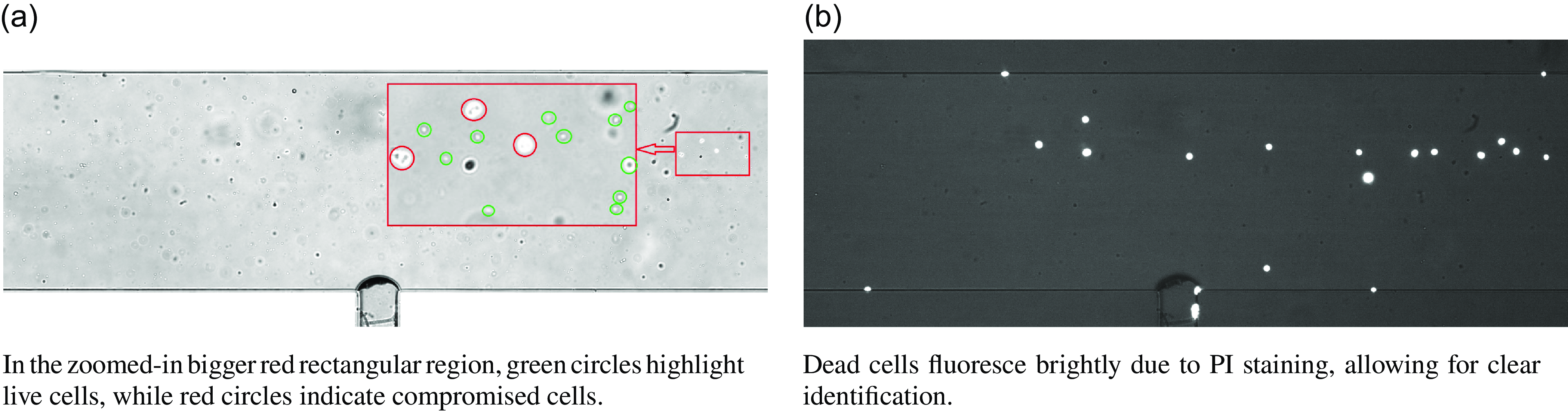
) and incubated for 10 minutes at room temperature, protected from light. PI is a membrane-impermeable dye that selectively penetrates cells with compromised membranes, intercalating with DNA/RNA and emitting red fluorescence when excited at 535 nm. Consequently, dead cells with damaged membranes exhibit strong fluorescence, while live cells, which maintain membrane integrity, remain unstained. To validate this detection method, images were captured under identical conditions (no flow) but two different illumination conditions, as shown in figure 1. The first image (figure 1
a) was taken with high background illumination (halogen light) and green LED excitation, allowing the identification of both live and compromised cells. In the zoomed-in red rectangular region, green circles highlight live cells, while red circles indicate compromised cells. The second image (figure 1
b) was captured with reduced background illumination, which preserves the visibility of key features within the region of interest (ROI), such as microbubbles and channel walls, while enhancing the fluorescence contrast of compromised cells. Under this condition, compromised cells fluoresce brightly due to PI staining, achieving a high signal-to-noise ratio, ensuring reliable detection.
$\unicode {x03BC}\mathrm {M}$
) and incubated for 10 minutes at room temperature, protected from light. PI is a membrane-impermeable dye that selectively penetrates cells with compromised membranes, intercalating with DNA/RNA and emitting red fluorescence when excited at 535 nm. Consequently, dead cells with damaged membranes exhibit strong fluorescence, while live cells, which maintain membrane integrity, remain unstained. To validate this detection method, images were captured under identical conditions (no flow) but two different illumination conditions, as shown in figure 1. The first image (figure 1
a) was taken with high background illumination (halogen light) and green LED excitation, allowing the identification of both live and compromised cells. In the zoomed-in red rectangular region, green circles highlight live cells, while red circles indicate compromised cells. The second image (figure 1
b) was captured with reduced background illumination, which preserves the visibility of key features within the region of interest (ROI), such as microbubbles and channel walls, while enhancing the fluorescence contrast of compromised cells. Under this condition, compromised cells fluoresce brightly due to PI staining, achieving a high signal-to-noise ratio, ensuring reliable detection.
The cell suspension, at a concentration of 1000 cells $\unicode {x03BC}\mathrm {l}^{-1}$
, was prepared for microfluidic experiments designed to enable the automatic identification and removal of dead cells, while monitoring cell viability under shear stress induced by microbubble flow. Approximately 0.1% of cells exhibited membrane damage and were detectable via fluorescence microscopy, further demonstrating the effectiveness of the imaging technique in providing clear differentiation between live and dead cells.
$\unicode {x03BC}\mathrm {l}^{-1}$
, was prepared for microfluidic experiments designed to enable the automatic identification and removal of dead cells, while monitoring cell viability under shear stress induced by microbubble flow. Approximately 0.1% of cells exhibited membrane damage and were detectable via fluorescence microscopy, further demonstrating the effectiveness of the imaging technique in providing clear differentiation between live and dead cells.
To further illustrate the experimental workflow, we have included an additional schematic of the test set-up and optical set-up in figure S1 of the supplementary material available at https://doi.org/10.1017/flo.2025.10, along with supplementary movie 1, which demonstrates dead cell sorting. This schematic details the process by which real-time microscopic images are acquired, analysed by the control system and used to activate the piezotransducer, which selectively removes dead cells from the microchannel.
Comparison of two imaging conditions used for identifying dead cells in a microfluidic channel. (a) High background illumination and green LED excitation reveal the overall cell distribution, including both live and dead cells. (b) Reduced background illumination highlights dead cells emitting PI fluorescence, ensuring high signal-to-noise detection.
3. Experimental set-up
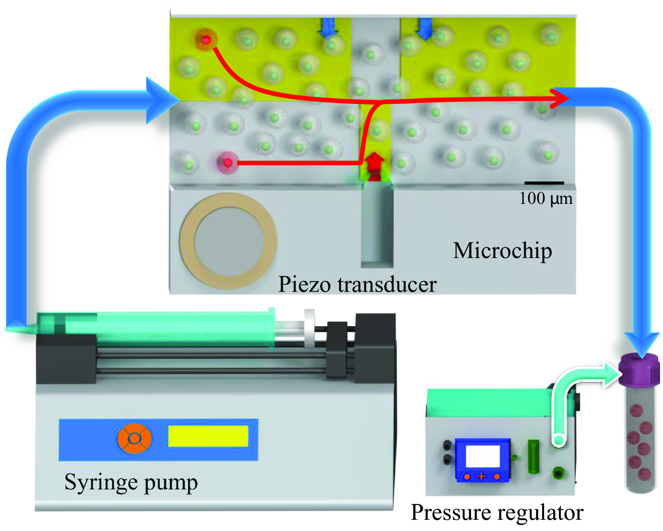
In this section, we detail the experimental design, as depicted in figure 2. The experimental set-up primarily consists of a microfluidic system, an optical configuration and a control system.
Microfluidic chip and its associated flow control system. The 20 mm microchannel features a rectangular cross-section (H = 100 $\unicode {x03BC}\mathrm {m}$
× W = 500
$\unicode {x03BC}\mathrm {m}$
× W = 500 $\unicode {x03BC}\mathrm {m}$
), with a central cavity measuring w = 80
$\unicode {x03BC}\mathrm {m}$
), with a central cavity measuring w = 80 $\unicode {x03BC}\mathrm {m}$
in width and h = 500
$\unicode {x03BC}\mathrm {m}$
in width and h = 500 $\unicode {x03BC}\mathrm {m}$
in length. A syringe pump regulates the flow rate, while a piezoelectric transducer stimulates a microbubble, and a pressure regulator stabilises liquid and bubble pressures. A customised LabVIEW control system enables real-time cell detection and tracking, adjusting the piezoelectric transducer to guide cells along red pathways to a target region for collection. Regions of interest (ROIs) for cell detection are marked in yellow, with blue arrows indicating downward flow and a red arrow representing upward flow generated by microbubble activation.
$\unicode {x03BC}\mathrm {m}$
in length. A syringe pump regulates the flow rate, while a piezoelectric transducer stimulates a microbubble, and a pressure regulator stabilises liquid and bubble pressures. A customised LabVIEW control system enables real-time cell detection and tracking, adjusting the piezoelectric transducer to guide cells along red pathways to a target region for collection. Regions of interest (ROIs) for cell detection are marked in yellow, with blue arrows indicating downward flow and a red arrow representing upward flow generated by microbubble activation.
3.1. Microfluidic system configuration
The microfluidic system, as depicted in figure 2, integrates transparent microchannels with sophisticated flow control mechanisms. The fabrication of the microchannels was carried out using the well-established soft lithography process, following the methodology outlined by Wang et al. (Reference Wang, Jalikop and Hilgenfeldt2012). The fabricated microchannel spans 20 mm in length and possesses a rectangular cross-section, with a height (H) of 100 $\unicode {x03BC}\mathrm {m}$
and a width (W) of 500
$\unicode {x03BC}\mathrm {m}$
and a width (W) of 500 $\unicode {x03BC}\mathrm {m}$
. Centrally located within the channel is a cavity, measuring 80
$\unicode {x03BC}\mathrm {m}$
. Centrally located within the channel is a cavity, measuring 80 $\unicode {x03BC}\mathrm {m}$
in width (w) and 500
$\unicode {x03BC}\mathrm {m}$
in width (w) and 500 $\unicode {x03BC}\mathrm {m}$
in length (h). This specific design allows for the controlled introduction and confinement of a gas pocket within the cavity when a liquid is infused into the channel.
$\unicode {x03BC}\mathrm {m}$
in length (h). This specific design allows for the controlled introduction and confinement of a gas pocket within the cavity when a liquid is infused into the channel.
The introduction of liquid into the microchannel results in the entrapment of a gas pocket, typically air, within the lateral cavity. This process leads to the formation of a quasi-cylindrical microbubble. It is noteworthy that the gas composition within the bubble is not limited to air; alternatives such as nitrogen, argon and helium, can be used. The choice of gas can be crucial, particularly in scenarios where the interaction between the fluid and atmospheric air must be avoided to maintain the integrity of the conveyed fluids or particles.
When the microbubble is subjected to bulk acoustic waves, generated by a piezoelectric transducer operating at or near the bubble’s resonant frequency, it induces primary oscillatory flow within the channel. This primary flow subsequently gives rise to secondary flow patterns, characterised by counter-rotating vortices along the channel walls (Marmottant & Hilgenfeldt Reference Marmottant and Hilgenfeldt2003; Riley Reference Riley2001; Versluis et al. Reference Versluis, Goertz, Palanchon, Heitman, van der Meer, Dollet, de Jong and Lohse2010).
To ensure experimental reproducibility, it is essential to maintain a consistent microbubble size. This can be achieved by continuously adjusting and controlling the pressure difference between the channel’s interior and the surrounding ambient pressure, as recommended by Volk & Kähler (Reference Volk and Kähler2018a). In this study, this approach was also employed to maintain a constant microbubble size throughout the experiments.
Precise regulation of the aqueous sample solution flow into the channel was performed using a syringe pump (neMESYS, Germany) and a pressure regulator (Fluigent MFCS T M-EZ, 0–1000 mbar, France). The bubble’s protrusion depth was continuously monitored using a camera, while a PID controller compared the detected size with the target and adjusted the applied pressure accordingly. As observed in our experiments, applying 6–8 mbar to the interior channel provided effective and stable bubble size control. Figure 2 provides a schematic overview of the experimental set-up. For further elaboration on the set-up and its components, readers are referred to Bakhtiari & Kähler (Reference Bakhtiari and Kähler2022).
3.2. Optical set-up
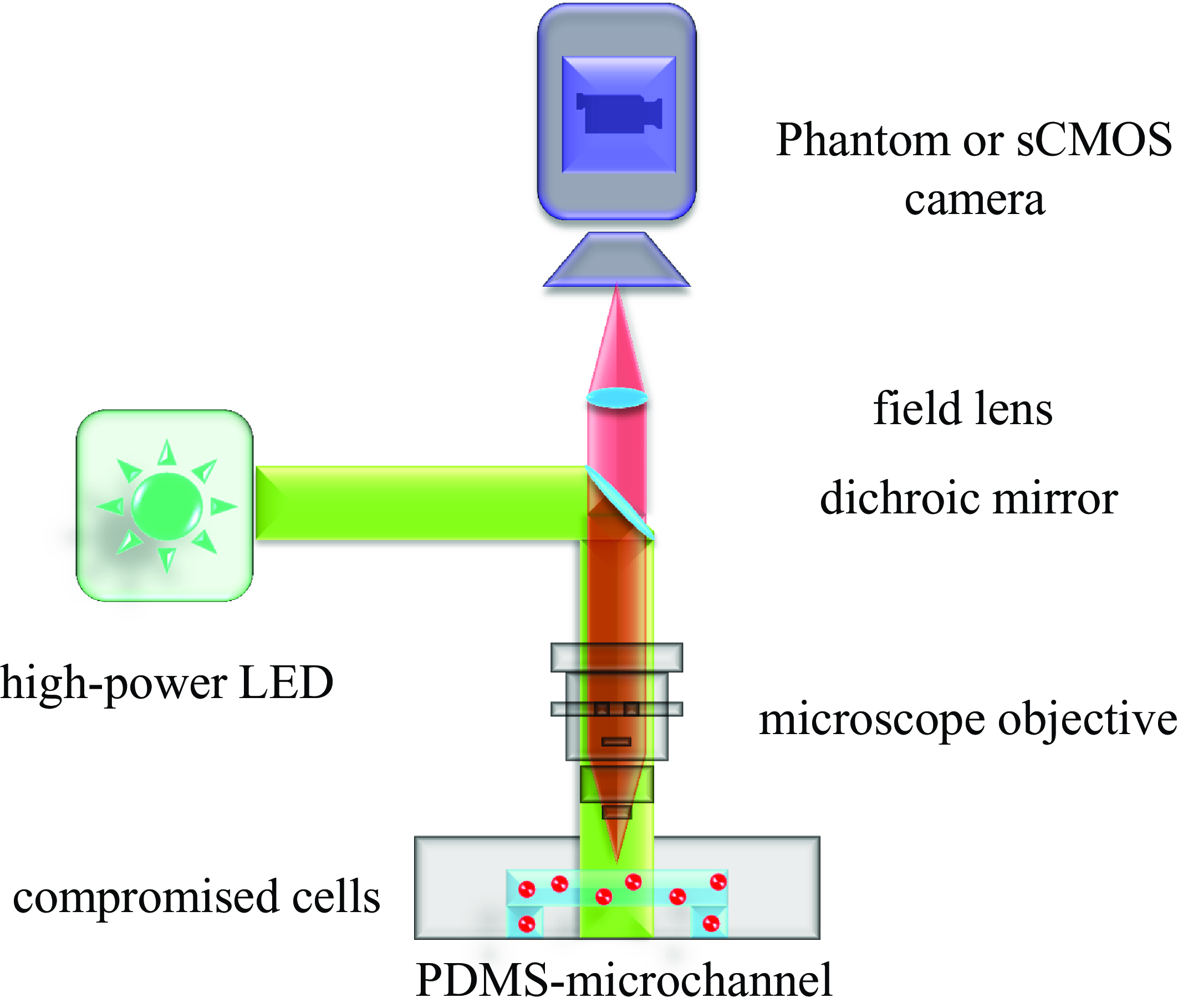
The optical set-up consists of an upright Zeiss AxioImager.Z2 microscope equipped with a customised fluorescence optical set-up, a 20× objective lens (EC Plan Neouar 20×/0.50 M27), an sCMOS camera (pco.edge 5.5) and a Phantom v2640 ONYX high-speed camera. This set-up enables both fluorescence imaging to detect PI-stained cells and high-speed imaging to capture fast flow dynamics. Although standard fluorescence filter cubes (which combine an excitation filter, dichroic mirror and emission filter) can also be used for this type of imaging, our system employs a customised optical set-up that simplifies the excitation and detection process. The system is optimised for fluorescence microscopy, using a dichroic mirror that efficiently reflects the excitation light from a high-power LED (Prizmatix UHP-T-520-EP) while transmitting the fluorescence emission from PI-stained dead cells to the sCMOS camera. This configuration ensures a high signal-to-noise ratio (SNR) by blocking excitation light and minimising background fluorescence, as illustrated in figure 3. The effectiveness of this set-up for detecting PI-stained dead cells with high contrast can be seen in figure 1(b), where dead cells fluoresce brightly, ensuring clear identification against a low-background signal.
Schematic of the optical set-up, including the Zeiss AxioImager.Z2 microscope, dichroic mirror, 20× objective lens and dual-camera system. This configuration allows for both fluorescence imaging and high-speed imaging of fluid dynamics.
To prevent photobleaching, the LED light source was pulsed and synchronised with the camera, ensuring minimal exposure while maintaining high fluorescence intensity.
For high-speed imaging of fluid dynamics, we used high-intensity white-light illumination from a 100 W halogen lamp instead of fluorescence excitation. This set-up achieved a 3000 kHz frame rate, which is critical for accurately resolving shear stress and flow patterns near the microbubble surface.
Fluorescence-based imaging is less effective in this context due to the high-intensity illumination required, which can exceed the optical system’s thresholds and risk damaging optical components. Additionally, reflections from bright particles near the microbubble surface can interfere with tracking accuracy, leading to measurement errors. Previous studies have demonstrated that white-light imaging with background illumination significantly reduces these artefacts, providing improved particle tracking and enabling precise capture of fast-flow structures (see Volk Reference Volk2020).
Flowchart of the cell sorting algorithm implemented in LabVIEW. The regions of interest (ROIs) are defined based on specific experimental parameters: y c denotes the channel width, y t represents the target position, x b is the centre of the microbubble, 2a is the width of the cavity, and e is the gap between the upward and downward flows. In this study, the gap values were set to $\textit {e}_{\mathrm {1}} = \textit {e}_{\mathrm {2}} = 150\,\unicode {x03BC}\mathrm {m}$
, according to the flow conditions.
$\textit {e}_{\mathrm {1}} = \textit {e}_{\mathrm {2}} = 150\,\unicode {x03BC}\mathrm {m}$
, according to the flow conditions.

3.3. Control system set-up
The operational control system, managed by LabVIEW (National Instruments, USA), is essential for the precise execution of the cell removal process. This system manages real-time image acquisition (50 fps was sufficient for this study) and performs image analysis to detect and track compromised cells. Once a damaged cell is identified within the field of view, LabVIEW controls the microbubble’s activation and deactivation based on the cell’s initial lateral position (y cell ) and the desired target position (y target ) downstream in the channel. Although this is the first application of such a control system to biological cells, similar systems have been successfully demonstrated for precise particle positioning in microfluidic environments, providing relevant groundwork for this study (Bakhtiari & Kähler Reference Bakhtiari and Kähler2022). However, the system in this work has been specifically developed and refined to meet the unique demands of biological cell manipulation rather than microparticles. Unlike polystyrene particles (PS-FluoRed), which are precisely sized, consistently fluorescent and resistant to aggregation, biological cells exhibit size variability, fluorescence intensity fluctuations and a higher tendency to cluster. To address these challenges, several advancements have been implemented, including enhanced morphological processing to improve the detection of non-spherical cells, and using the ‘Fill Holes’ method to correct for uneven fluorescence labelling. Adaptive thresholding has been incorporated to automatically adjust detection thresholds based on variations in fluorescence intensity among labelled cells. Gaussian and median filtering have been applied to reduce noise while preserving fluorescent cell boundaries, improving accuracy under non-uniform illumination. The system now supports size range detection, allowing for dynamic adjustments within a range of cell sizes rather than relying on a fixed particle size. Additionally, triggering and synchronisation of the camera and LED excitation have been optimised to minimise photobleaching, ensuring stable fluorescence detection over time. These refinements significantly enhance the system’s ability to accurately detect, track and manipulate biological cells, making it more robust and adaptable than previous versions designed for microparticles. As illustrated in the simplified flowchart of the control system in figure 4, the system automatically determines the location and size of regions of interest (ROIs), which are critical for accurate cell positioning, based solely on the target specified by the operator. This automation streamlines the process, allowing for more efficient and reliable cell handling.
Bulk acoustic waves generated by a piezoelectric transducer induce primary oscillations of the bubble’s surface, which, in the presence of channel walls, produce secondary streaming patterns around the bubble. These streaming patterns manifest as counter-rotating vortices (figure 6), which are crucial for maneuvring cells within the microchannel. The rotational direction of these vortices is determined by the applied frequency (Rallabandi et al. Reference Rallabandi, Wang and Hilgenfeldt2014). When a target cell is detected within the ROIs since the y-direction (y cell ) differs from the predefined target position (y target ), the system activates the microbubble to induce controlled streaming flows and remains active as long as the target cell is within the ROIs until the cell is successfully evicted from the ROIs and aligned with y target , the microbubble, then is deactivated, allowing the cell to maintain its position and continue along the Poiseuille flow at a nearly constant lateral level until reaching the end of the microchannel. Due to the counter-rotating nature of the vortices, the transition between the upward flow (directly above the bubble) and the downward flows (upstream and downstream of the bubble) does not occur at a single, sharply defined x-location. Instead, this transition extends over a finite spatial range, forming a gap region between the upward flow zone (3 in figure 4) and the downward flow regions (1 and 2 in figure 4). Within this gap, the flow gradually changes direction rather than shifting abruptly. This region ensures that any cell entering the ROIs experiences a well-defined and consistent downward or upward flow, depending on its position relative to the bubble. Downward flows steer cells toward the bubble’s periphery (negative y-direction), while the upward flow pushes cells away from the bubble (positive y-direction), facilitating precise repositioning to y target , as illustrated in figure 4.
To facilitate this process, a function generator (GW INSTEK AFG-2225) and an amplifier (Krohn-Hite 7500) deliver a predefined electrical signal, tuned to the microbubble’s resonant frequency, to the piezoelectric transducer on the microfluidic chip. The function generator is synchronised with a National Instruments USB-6002 DAQmx data acquisition device, controlled by LabVIEW. This set-up allows for precise triggering of the function generator at specific intervals and durations, making the system adaptable to various experimental conditions, including different flow rates, cell sizes, channel dimensions and microstreaming intensities, as illustrated in figure 2.
4. Results and discussion
4.1. Automatic removal of dead cells
For the first time, a series of systematic experiments demonstrated the use of an automated positioning and removal technique on biological cells. The developed method autonomously identifies and monitors compromised cells. Once detected, they are removed from the primary fluid using ultrasound-driven microbubble streaming.
In this study, we used a diluted solution of propidium iodide containing PBMCs (see § 2.2). The solution had a concentration of 1000 cells per microlitre. Approximately 1 in 1000 cells were damaged. These damaged cells emitted red fluorescence, making them detectable under fluorescent optical microscopy.
The experiments focused on positioning these individual cells within two regions across the width of a 500 $\unicode {x03BC}\mathrm {m}$
microchannel. The regions included the upper and bottom parts of the channel. The method allowed cells to be redirected effectively. This system has practical applications, enabling operators to guide individual cells into a designated outlet downstream. Cells could either be collected for analysis or sent to a waste exit, thereby purifying the main fluid.
$\unicode {x03BC}\mathrm {m}$
microchannel. The regions included the upper and bottom parts of the channel. The method allowed cells to be redirected effectively. This system has practical applications, enabling operators to guide individual cells into a designated outlet downstream. Cells could either be collected for analysis or sent to a waste exit, thereby purifying the main fluid.
The experiments used microbubbles with dimensions (w = 80 $\unicode {x03BC}\mathrm {m}$
and d = 0.5a) and oscillating at a frequency of 18.9 kHz and voltage of 70 vpp. Fluid was pumped into the channel at a flow rate of 0.014
$\unicode {x03BC}\mathrm {m}$
and d = 0.5a) and oscillating at a frequency of 18.9 kHz and voltage of 70 vpp. Fluid was pumped into the channel at a flow rate of 0.014 $\unicode {x03BC}\mathrm {l}\,{\rm s}^{-1}$
. The bubble’s surface height was controlled by maintaining a constant pressure difference between the inlet and ambient pressure, ensuring no changes in bubble size.
$\unicode {x03BC}\mathrm {l}\,{\rm s}^{-1}$
. The bubble’s surface height was controlled by maintaining a constant pressure difference between the inlet and ambient pressure, ensuring no changes in bubble size. $\unicode {x03BC}\mathrm {PTV}$
results showing the successful detection, tracking and removal of compromised cells from the main flow of live cells (not visible here, but present at a concentration of 1000 cells per microlitre in the mainstream) in a 500
$\unicode {x03BC}\mathrm {PTV}$
results showing the successful detection, tracking and removal of compromised cells from the main flow of live cells (not visible here, but present at a concentration of 1000 cells per microlitre in the mainstream) in a 500 $\unicode {x03BC}\mathrm {m}$
microchannel. In panel (a), the damaged cells are directed to the target area in the upper part of the channel (red region), while panel (b) shows cells being diverted to the target area in the lower part of the channel. Microbubbles are activated within the yellow ROIs to remove the damaged cells once detected inside these regions.
$\unicode {x03BC}\mathrm {m}$
microchannel. In panel (a), the damaged cells are directed to the target area in the upper part of the channel (red region), while panel (b) shows cells being diverted to the target area in the lower part of the channel. Microbubbles are activated within the yellow ROIs to remove the damaged cells once detected inside these regions.
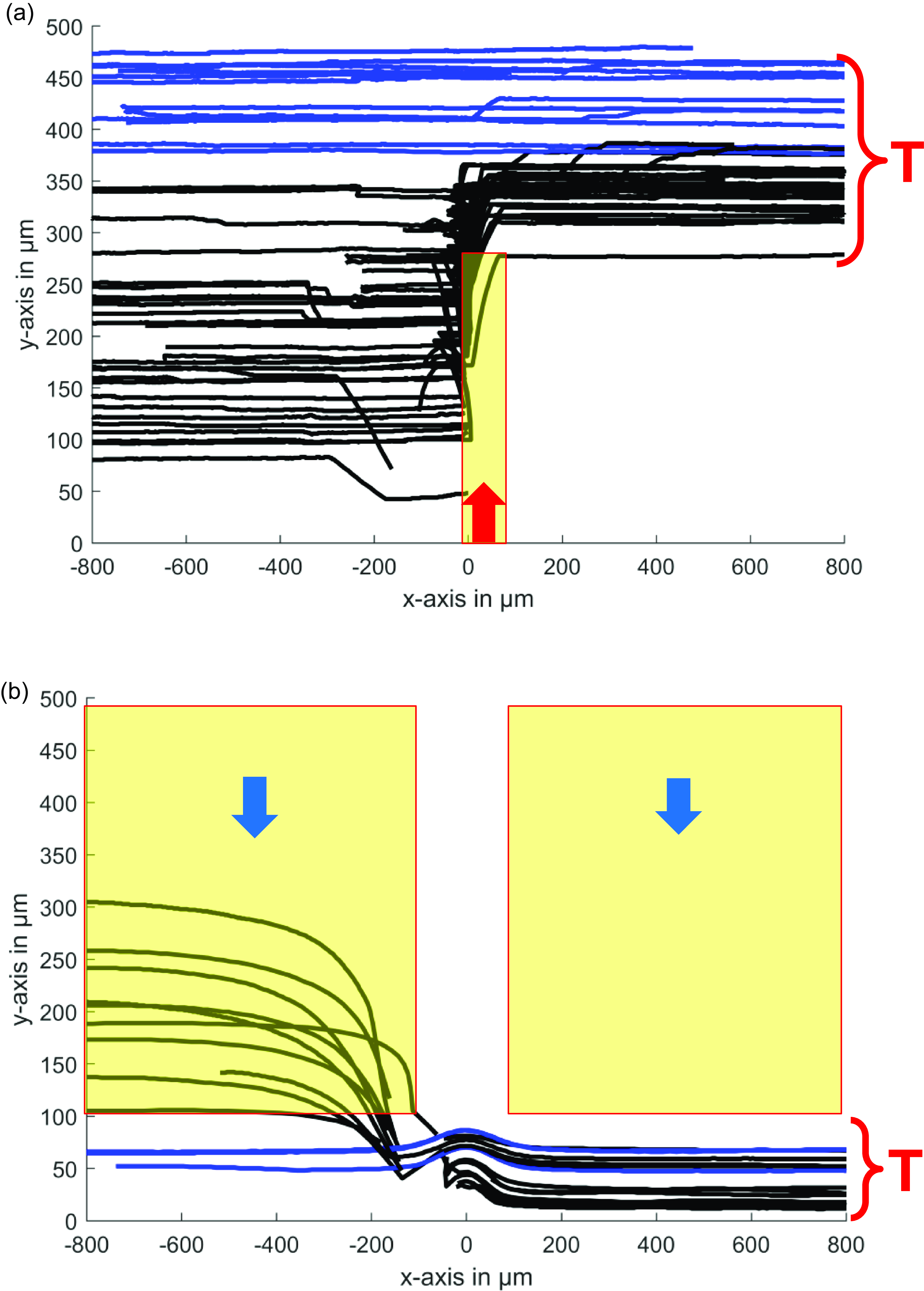
To assess the accuracy of the automated cell sorting system, real-time operation images (captured at 50 fps) were stored and analysed using an in-house microparticle tracking velocimetry ( $\unicode {x03BC}\mathrm {PTV}$
) algorithm. The resulting cell tracks are shown in figure 3, demonstrating the successful sorting of compromised cells in two different scenarios: focusing cells towards the upper part of the channel (figure 3
a) and towards the lower part (figure 5
b). In both cases, the black tracks indicate cells affected by bubble actuation, while blue tracks represent cells that were already correctly positioned at the desired y-location, where no bubble actuation was required. In regions near the bubble, where streaming velocities are highest, cells undergo rapid acceleration. Due to the optimised real-time imaging at 50 fps, this rapid movement can lead to challenges in time-resolved tracking. However, this does not affect the overall accuracy of the sorting operation. The interruptions or abrupt changes in some cell tracks simply reflect the high velocities in these regions, and manual verification confirmed that these tracks still correspond to the same target cells. Notably, although the technique was primarily designed for handling single or rare cells, it was observed that in some instances where multiple dead cells were present within the field of veiw (FOV), the system was still able to successfully manage and redirect them. However, we acknowledge that when adjacent cells, such as a live and a dead cell, are in close proximity, they may occasionally move together due to local flow interactions. This effect does not significantly impact the technique’s intended function, as the system prioritises the removal of dead cells, ensuring a cleaner fluid environment.
$\unicode {x03BC}\mathrm {PTV}$
) algorithm. The resulting cell tracks are shown in figure 3, demonstrating the successful sorting of compromised cells in two different scenarios: focusing cells towards the upper part of the channel (figure 3
a) and towards the lower part (figure 5
b). In both cases, the black tracks indicate cells affected by bubble actuation, while blue tracks represent cells that were already correctly positioned at the desired y-location, where no bubble actuation was required. In regions near the bubble, where streaming velocities are highest, cells undergo rapid acceleration. Due to the optimised real-time imaging at 50 fps, this rapid movement can lead to challenges in time-resolved tracking. However, this does not affect the overall accuracy of the sorting operation. The interruptions or abrupt changes in some cell tracks simply reflect the high velocities in these regions, and manual verification confirmed that these tracks still correspond to the same target cells. Notably, although the technique was primarily designed for handling single or rare cells, it was observed that in some instances where multiple dead cells were present within the field of veiw (FOV), the system was still able to successfully manage and redirect them. However, we acknowledge that when adjacent cells, such as a live and a dead cell, are in close proximity, they may occasionally move together due to local flow interactions. This effect does not significantly impact the technique’s intended function, as the system prioritises the removal of dead cells, ensuring a cleaner fluid environment.
Given the dimensions of the FOV – length, 1600 $\unicode {x03BC}\mathrm {m}$
; width, 500
$\unicode {x03BC}\mathrm {m}$
; width, 500 $\unicode {x03BC}\mathrm {m}$
; height, 100
$\unicode {x03BC}\mathrm {m}$
; height, 100 $\unicode {x03BC}\mathrm {m}$
– the total volume is 0.08
$\unicode {x03BC}\mathrm {m}$
– the total volume is 0.08 $\unicode {x03BC}\mathrm {l}$
, corresponding to approximately 80 cells, assuming a semi-homogeneous distribution. However, the number of cells within the ROIs varies depending on the final target position, typically covering 20 %–90 % of the FOV. The ROI is smaller when cells need to be pushed away from the bubble, as only a single small ROI exists above the bubble, while it is larger when cells must be dragged towards the bubble, with additional ROIs located both upstream and downstream.
$\unicode {x03BC}\mathrm {l}$
, corresponding to approximately 80 cells, assuming a semi-homogeneous distribution. However, the number of cells within the ROIs varies depending on the final target position, typically covering 20 %–90 % of the FOV. The ROI is smaller when cells need to be pushed away from the bubble, as only a single small ROI exists above the bubble, while it is larger when cells must be dragged towards the bubble, with additional ROIs located both upstream and downstream.
The effectiveness of the method is largely dependent on target cell concentration rather than the overall live cell density. The system operates optimally when one target cell is processed at a time, and the sorting efficiency is influenced by the ratio of Poiseuille flow to microstreaming forces. Proper tuning of these parameters ensures that the microstreaming effect covers the entire width of the microchannel, allowing precise redirection of target cells. Live cells that are not targeted are systematically ignored by the system (i.e. not detected or processed), meaning their concentration can theoretically be as high as necessary, provided that it does not alter the fundamental flow topology of the counter-rotating vortices. However, at very high live cell concentrations, the likelihood of live cells moving alongside dead cells may increase.
Additionally, the sorting rate can be enhanced by increasing the microchannel depth to accommodate higher flow rates. However, excessively deep channels or excessively high flow rates may surpass the resolution limits of the microscopy imaging system, potentially affecting detection accuracy. Furthermore, as previously shown through high-frequency imaging of counter-rotating vortices (Bakhtiari & Kähler Reference Bakhtiari and Kähler2024a), microstreaming develops almost instantaneously upon activation of the piezo transducer, enabling real-time cell sorting. For a more detailed explanation of the technique, including its underlying principles and experimental conditions, we refer the reader to Bakhtiari & Kähler (Reference Bakhtiari and Kähler2022).
These findings confirm that the proposed method can autonomously detect, track and guide biological cells to precise downstream locations. Despite its primary design for low target cell concentrations, the technique has demonstrated robustness and applicability to more complex scenarios, offering the potential for broader applications in lab-on-a-chip systems and medical diagnostics.
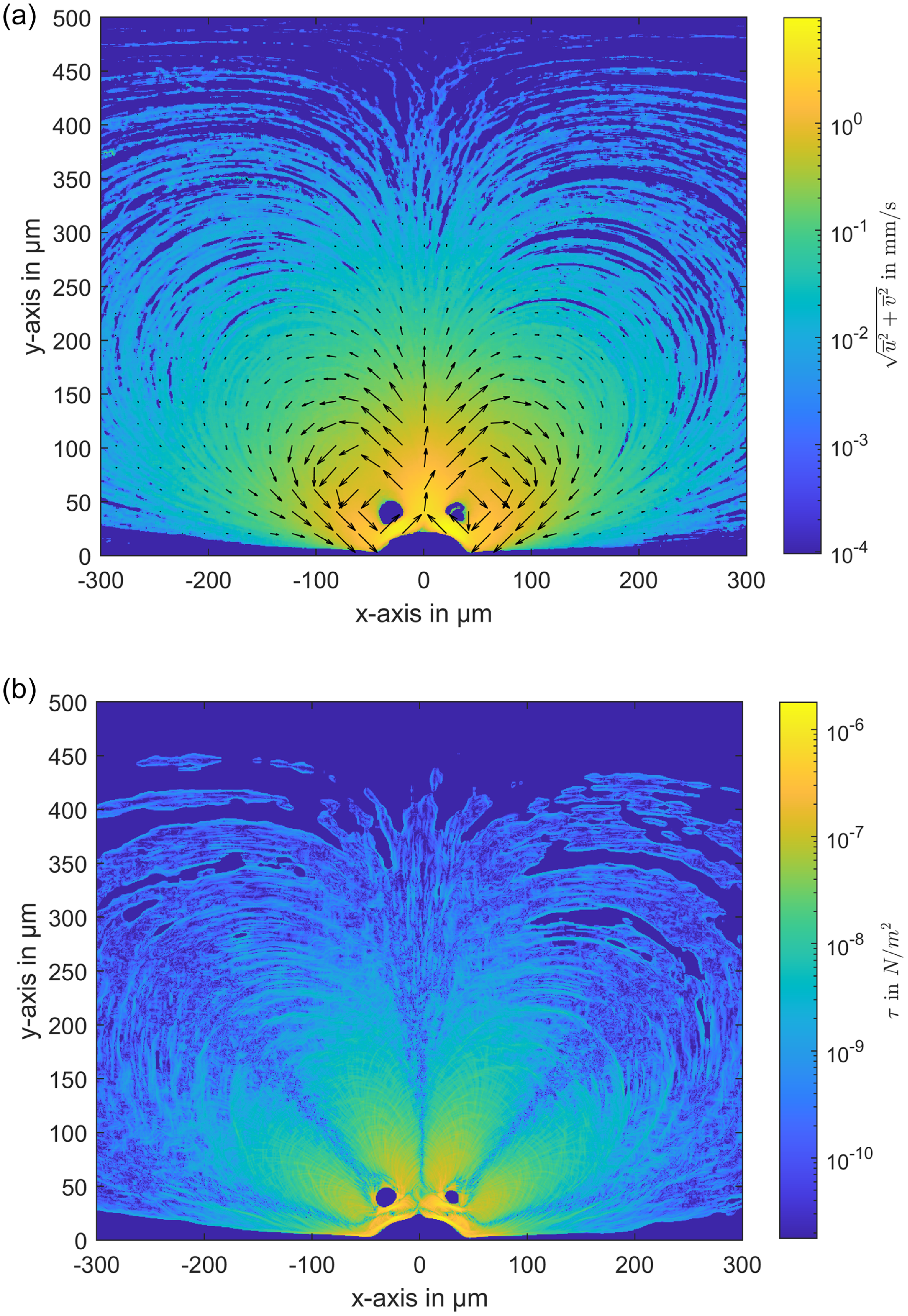
Velocity field and shear stress distribution induced by an actuated microbubble. (a) Velocity field around the microbubble. (b) Corresponding shear stress distribution.
When studying cell manipulation through microbubble streaming, it is crucial to ensure that cells are not subjected to harmful levels of shear stress. In this study, we used 2 $\unicode {x03BC}\mathrm {m}$
buoyant polystyrene particles to measure the velocity field within the effective streaming region. Based on these measurements, we calculated the shear stress distribution around the bubble (see figure 6).
$\unicode {x03BC}\mathrm {m}$
buoyant polystyrene particles to measure the velocity field within the effective streaming region. Based on these measurements, we calculated the shear stress distribution around the bubble (see figure 6).
The in-house algorithm General Defocusing Particle Tracking (GDPT) (Barnkob et al. 2015) was employed to track the 2 $\unicode {x03BC}\mathrm {m}$
tracer particles in the streaming flow generated by the oscillating microbubble driven by the piezoelectric transducer. The measured velocity data, based on the scattered particle tracks, were interpolated onto a regular grid and averaged to obtain the velocity fields. The resolution of the grid used for interpolation was 0.68
$\unicode {x03BC}\mathrm {m}$
tracer particles in the streaming flow generated by the oscillating microbubble driven by the piezoelectric transducer. The measured velocity data, based on the scattered particle tracks, were interpolated onto a regular grid and averaged to obtain the velocity fields. The resolution of the grid used for interpolation was 0.68 $\unicode {x03BC}\mathrm {m}\,{\rm pixel}^{-1}$
. Figure 6(a) illustrates the velocity magnitude on a logarithmic scale, with superimposed vectors to indicate the flow direction of the counter-rotating vortices, featuring an upward flow above the bubble and downward flows both upstream and downstream. The maximum velocity, ranging between 5 and 8 mm s−1, is observed near the bubble, particularly at the centre of the cavity where the flow moves away from the bubble. Using these averaged velocity field data, the shear stress distribution was calculated and is presented in figure 6(b).
$\unicode {x03BC}\mathrm {m}\,{\rm pixel}^{-1}$
. Figure 6(a) illustrates the velocity magnitude on a logarithmic scale, with superimposed vectors to indicate the flow direction of the counter-rotating vortices, featuring an upward flow above the bubble and downward flows both upstream and downstream. The maximum velocity, ranging between 5 and 8 mm s−1, is observed near the bubble, particularly at the centre of the cavity where the flow moves away from the bubble. Using these averaged velocity field data, the shear stress distribution was calculated and is presented in figure 6(b).
Our measurements indicate that the maximum shear stress of τ = 1 × 10⁻⁶ N m−2 is concentrated near the bubble surface. This value is substantially lower than the critical shear stress thresholds for most biological cells, such as 150 N m−2 for red blood cells (RBCs) or 10 N m−2 for white blood cells (WBCs) (Zhao et al. Reference Zhao, Yu, Zhao, Xu, He, Lin and Zhang2022; Espina et al. Reference Espina, Cordeiro, Milivojevic, Pajić-Lijaković and Barriga2023). Furthermore, the highest shear stress region is highly localised, confined to a very small area near the bubble, and the stress drops rapidly just a few micrometres away from the surface. This rapid decrease in shear stress ensures that biological cells located further from the bubble experience minimal stress, thus significantly reducing the likelihood of cellular damage. In the core regions of the induced vortices, accurate measurements of velocity – and consequently, shear stress – were not possible, as even the small 2 $\unicode {x03BC}\mathrm {m}$
tracer particles did not penetrate these areas. This absence of particles in the vortex centres is a physical effect caused by the rotation of the vortices and the inertia of the particles, which prevents them from being drawn into the core. Instead, they remain in the outer orbits of the vortices. A similar mechanism applies to biological cells, which are significantly larger than the tracer particles. Due to their inertia, they can be expected to follow comparable trajectories, remaining in the outer vortex regions rather than being drawn into the core. Assuming the fluid in the vortex core undergoes pure rotation, the shear stress in these regions – where velocities were not directly measured – can be estimated analytically based on the measured velocities surrounding the core. This estimation reveals very low shear stresses, approximately 10 times lower than the maximum shear stress near the bubble. Despite the uncertainty in the exact shear stress at the vortex centres, this does not significantly affect cell viability, as biological cells are unlikely to enter these regions due to their inertia and the flow dynamics of the vortices. Overall, the localised nature of the high-shear regions near the bubble, along with the rapid decline in shear stress further away, ensures that cells remain protected from potential damage while being effectively manipulated by microbubble streaming. These findings are crucial in demonstrating the biocompatibility of ultrasound-driven microbubble streaming, confirming that the system operates well within safe shear stress limits, allowing for efficient manipulation of biological cells without causing mechanical damage.
$\unicode {x03BC}\mathrm {m}$
tracer particles did not penetrate these areas. This absence of particles in the vortex centres is a physical effect caused by the rotation of the vortices and the inertia of the particles, which prevents them from being drawn into the core. Instead, they remain in the outer orbits of the vortices. A similar mechanism applies to biological cells, which are significantly larger than the tracer particles. Due to their inertia, they can be expected to follow comparable trajectories, remaining in the outer vortex regions rather than being drawn into the core. Assuming the fluid in the vortex core undergoes pure rotation, the shear stress in these regions – where velocities were not directly measured – can be estimated analytically based on the measured velocities surrounding the core. This estimation reveals very low shear stresses, approximately 10 times lower than the maximum shear stress near the bubble. Despite the uncertainty in the exact shear stress at the vortex centres, this does not significantly affect cell viability, as biological cells are unlikely to enter these regions due to their inertia and the flow dynamics of the vortices. Overall, the localised nature of the high-shear regions near the bubble, along with the rapid decline in shear stress further away, ensures that cells remain protected from potential damage while being effectively manipulated by microbubble streaming. These findings are crucial in demonstrating the biocompatibility of ultrasound-driven microbubble streaming, confirming that the system operates well within safe shear stress limits, allowing for efficient manipulation of biological cells without causing mechanical damage.
4.2. Monitoring cell viability under shear stress induced by microbubble streaming
To expand on previous findings, where the shear stress distribution around the microbubble was mapped (see figure 6), it was necessary to validate these results using live cells to assess the biocompatibility of the induced flows. A critical experiment was conducted in the microchannel under conditions without Poiseuille flow, allowing for the isolation of microbubble-induced shear stress effects on the cells. In this set-up, cells were continuously exposed to the shear stress generated by the oscillating microbubble for over two hours, ensuring a thorough evaluation of the long-term impact of the shear forces on cell viability and function. To assess whether the cells experienced damage under these conditions, propidium iodide (PI) was introduced into the aqueous phase. This marker enabled real-time monitoring of cell viability during the experiment. To mitigate potential photodegradation of the dye and prevent cellular damage from continuous high-intensity light exposure, the high-power LED was pulsed and synchronised with the camera’s recordings at a frequency of 0.1 Hz, providing a brief flash of light every 10 s for imaging purposes.
The results showed that, despite being exposed to microbubble-induced shear stress for two hours, none of the approximately 40 cells in the field of view exhibited signs of damage. The absence of fluorescence confirmed that the cell membranes remained intact, indicating no compromise to their viability throughout the experiment.
These findings strongly suggest that under typical microbubble streaming conditions, the risk of cell damage is extremely low, even with prolonged exposure. This reinforces the biocompatibility of microbubble streaming as a reliable and safe technique for cell manipulation in microfluidic systems, making it a powerful tool for cell sorting, purification and positioning without adversely affecting cell health.
5. Conclusions
This study successfully demonstrated the feasibility of using ultrasound-driven microbubble streaming for precise human cell manipulation in microfluidic environments while maintaining cell integrity. Additionally, the developed automated system effectively detected, tracked and redirected compromised cells from the primary fluid stream, showcasing its potential for lab-on-a-chip applications and medical diagnostics.
Detailed measurements of the shear stress distribution around the microbubble revealed that while the highest stress occurred near the bubble, it decreased rapidly with distance. The maximum shear stress, approximately τ = 1 × 10⁻⁶ N m−2, was significantly below the critical threshold for most biological cells and was confined to a small region near the bubble. This localised stress distribution ensures that cells experience minimal shear stress outside this region, substantially lowering the risk of cellular damage. Furthermore, the study confirmed that due to their larger size compared with the tracer particles used, cells are unlikely to be drawn into the core of the counter-rotating vortices.
However, beyond validating expected safety margins, these measurements also account for possible unanticipated effects from the experimental environment. Unlike purely theoretical predictions, which may neglect superimposed acoustic, electric or microfluidic boundary effects, direct shear stress mapping ensures that all dynamic interactions within the system are properly captured.
Long-term monitoring of cell viability under shear stress provided further confirmation of the biocompatibility of microbubble streaming. Cells exposed to bubble-induced flow for over two hours exhibited no signs of damage, as indicated by the absence of fluorescence from propidium iodide staining. This suggests that the shear stress generated by microbubble streaming is well below the threshold that could compromise cell membrane integrity, even during prolonged exposure. In conclusion, this work emphasises the biocompatibility and precision of microbubble streaming for non-invasive cell manipulation and sorting. The findings support its broader application in biomedical fields, including automated dead cell removal and selective cell positioning, without negatively affecting cell viability.
Supplementary material
The supplementary material for this article can be found at https://dx.doi.org/10.1017/flo.2025.10.
Data availability statement
Raw data are available from the corresponding author Amirabas Bakhtiari.
Author contributions
Amirabas Bakhtiari: conceptualisation, methodology, data acquisition and analysis, original draft writing. Benedikt Schumm: conceptualisation, methodology, data acquisition and analysis, original draft writing. Martin Schönfelder: conceptualisation, methodology, review and editing. Christian J. Kähler: conceptualisation, methodology, supervision, review and editing, funding acquisition.
Funding
We acknowledge financial support by Universität der Bundeswehr München.
Competing interests
The authors declare no conflict of interest.
Ethical statement
The research meets all ethical guidelines, including adherence to the legal requirements of the study country.


 Open access