


1. Introduction
Terrain formerly covered by an ice sheet is often characterized by the widespread presence of subglacial landforms. The most common of these landforms is the drumlin, an oval-shaped hill with a relatively symmetrical profile, an average width of ~200 m, a length of 600 m and a relief of ~7 m (Reference Clark, Hughes, Greenwood, Spagnolo and NgClark and others, 2009; Reference Spagnolo, Clark, Hughes, Dunlop and StokesSpagnolo and others, 2010, Reference Spagnolo, Clark and Dunop2011, Reference Spagnolo and Clark2012). Drumlins are elongated in the direction of ice flow and tend to occur in clusters of similarly oriented swarms, commonly called drumlin fields or flowsets (e.g. Reference Boulton and ClarkBoulton and Clark, 1990). Despite their widespread presence and a history of research dating back three centuries (Reference MenziesMenzies, 1984), drumlins remain among the most enigmatic landforms on Earth, with many, sometimes opposing, formation theories having been formulated and in many instances still being debated (e.g. Reference FairchildFairchild, 1929; Reference Smalley and UnwinSmalley and Unwin, 1968; Reference DardisDardis, 1985; Reference Boulton, Menzies and RoseBoulton, 1987; Reference HindmarshHind-marsh, 1998). Agreement, for example, as to whether drumlins are erosional, depositional or deformational features, or may represent a case of geomorphological equifinality, has yet to be met. The topic is significant because drumlins are formed at the ice–bed interface, which plays a major role in the dynamics of ice sheets and likely modulates their response to climate forcing (e.g. Reference Kleman and GlasserKleman and Glasser, 2007).
Drumlin internal composition can shed light on the formation of drumlins and, more generally, on the processes that operate at the ice–bed interface. The many studies on this topic have indicated that drumlins are often made of till, but stratified deposits and bedrock have also been found; in fact their internal composition appears to be variable between, and sometimes even within, flowsets (Reference PattersonPatterson and Hooke, 1995; Reference Stokes, Spagnolo and ClarkStokes and others, 2011, and references therein). Two key aspects of drumlin ‘sedimentology’ that need to be resolved are: (1) the relationship between the sedimentary body of drumlins and their substrate (e.g. bedrock); and (2) the nature of the inter-drumlin areas. The former is important because many theories, either explicitly or implicitly, suggest that drumlins represent an accumulation/erosion of sediment around a nucleus/obstacle usually made of bedrock or less deformable sediment (e.g. Reference Boulton, Menzies and RoseBoulton, 1987; Reference Dardis and HanveyDardis and Hanvey, 1994). The latter is crucial for evaluation of postglacial modification of the original landform (Reference FinlaysonFinlayson, 2013) and to verify the overall geometry of a drumlinized terrain (Reference Spagnolo and ClarkSpagnolo and others, 2012); for example, are drumlins blisters over a flat surface or do they represent a continuous sinusoidal surface? This has implications for the correct evaluation of drumlin heights as well as testing some of the most recent formation theories (e.g. Reference Stokes, Fowler, Clark, Hindmarsh and SpagnoloHindmarsh, 1999; Reference Fowler, Maltman, Hubbard and HambreyFowler, 2000).
Despite their importance, most sedimentological studies are limited to direct observations of a small number of two-dimensional (2-D) outcrops from only a few landforms (Reference Stokes, Spagnolo and ClarkStokes and others, 2011). Arguably, a more comprehensive study that might be able to cover more aspects of the overall structure of a drumlinized terrain, which ideally includes a large number of features, is necessary for an improved understanding of the processes involved. This cannot be achieved by investigation of outcrops alone simply because they are too limited, and detailed sedimentological investigations are too time-consuming, so alternative approaches are needed. Recent work has recognized the potential of using geophysical techniques (e.g. reflection seismic) to investigate the internal structure of glacial bedforms (e.g. Reference Fiore, Pugin and BeresFiore and others, 2002; Reference Kulessa, Clarke, Hughes, Barbour, Hambrey, Christoffersen, Glasser and HubbardKulessa and others, 2007; Reference Burke, Woodward, Russell, Fleisher and BaileyBurke and others, 2010; Reference Hiemstra, Kulessa, King and NtarlagiannisHiemstra and others, 2011; Reference Trommelen, Ross and IsmailTrommelen and others, 2014). However, in order to generate large datasets, the speed at which data can be collected must be a major consideration. Ground-penetrating radar (GPR) is now considered one of the most powerful geophysical techniques for the investigation of shallow sediments (e.g. Reference NealNeal, 2004), and it offers the potential for rapid data collection, but its feasibility for the study of subglacial bedforms is yet to be fully tested.
In this paper, we present the GPR analysis of five drumlins in the Upper Eden Valley, Cumbria, UK. The main aim of this work is to test the effectiveness of the GPR technique in order to analyse:
-
1. the relationship between drumlins and their substrate
-
2. the geometry of the inter-drumlin area
-
3. drumlin internal architecture.
These three objectives are pertinent to testing drumlin formation theories but we refrain from this in this study due to the limited number of drumlins investigated, i.e. it would be equivalent to using the evidence from five outcrops, an approach that has demonstrably failed to deliver consensus. This work shows that GPR represents a powerful tool that can be used for the investigation of drumlins. Future investigations need to be applied across a much greater spatial scale, encompassing large numbers of landforms and thus having the real potential of finally solving the puzzle of drumlin formation.
2. Study Area And Methodology
Environmental conditions are of extreme importance in the acquisition of GPR data, the success of which is therefore highly dependent on identifying areas with favourable ground settings. For this specific work, three criteria were adopted for the selection of the most suitable site:
-
1. an easily accessible area rich in drumlins (for logistical reasons in this instance)
-
2. a site characterized by close-to-surface bedrock, so that the contact between the drumlinized sediment and the underlying bedrock is likely within the range of GPR penetration
-
3. an area where the drumlinized terrain is well drained and there is a deep water table, because GPR signals are strongly attenuated below the water table.
The Eden Valley is a region of the UK where drumlins are particularly abundant, and it is the subject of some of the classic papers on British drumlins (Reference HollingworthHollingworth, 1931; Reference Riley, Menzies and RoseRiley, 1987; Reference Mitchell and RileyMitchell and Riley, 2006). Along the flanks of the main valley, which runs approximately from southeast to northwest, it is relatively common to see exposed bedrock, especially at its up-valley end, to the southeast. The field site selected for this work (Fig. 1) is 3 km southwest of the village of Kirkby Stephen and at the southeast end of the Eden Valley. The site contains a small quarry and some bedrock outcrops (Fig. 2), indicating the proximity of bedrock to the surface and allowing for direct measurements (dip and strike) of the geological structure. Bedrock lithology is Carboniferous limestone belonging to the Potts Beck Formation (BGS, 1997), a classic permeable rock type that should minimize the presence of water in the subsurface. Since this drumlin field is located on the flank of the main valley (~100 m higher than the thalweg), drainage is also naturally facilitated by the topographic setting.
Map illustrating the drumlins (in red) in the upper (southeast) Eden Valley, UK (drumlins original mapping and further details can be found in Reference Hughes, Clark and JordanHughes and others, 2010) (a), within which five drumlins (outlined in red) were selected for this study (b). Numbers in (b) represents contour heights in m a.s.l. The reconstructed palaeo-ice-flow direction for this area is from southwest to northeast.

Detail map illustrating the profiles acquired in the study area and their position relative to the drumlins, as well as the location of bedrock outcrops (with geological measurements of strata dip), relevant vegetation, roads and walls. Numbers next to strata dip symbols indicate the measured dip of the limestone strata. Numbers in blue are GPR profile IDs.

The analysis focused on five drumlins characterized by a length of 175–479 m, a width of 89–230 m, an elongation (length/width) ratio of 2.0–2.4 and a height of 2–30 m. These drumlins are generally aligned in a south-southwest–north-northeast direction. The reconstructed main palaeo-ice-flow direction of the drumlin flowset is from south to north (Reference Hughes, Clark and JordanHughes and others, 2014). The general land cover is pasture, i.e. grass fields bounded by dry stone walls, with sparse trees and shrubs (Fig. 3). Since some of these elements (e.g. walls) have an effect on GPR acquisition, they were mapped in the field and from satellite images (Fig. 2). The literature on drumlins in this region (Reference HollingworthHolling-worth, 1931; Reference Riley, Menzies and RoseRiley, 1987; Reference Mitchell and RileyMitchell and Riley, 2006), the available geological map (BGS, 1997) and the analysis of nearby boreholes (British Geological Survey borehole records) all suggest that drumlins here are largely composed of diamict. This is supported by observation of a few small exposures available in the field.
Photograph of the study area. The picture shows the drumlin along which GPR profile 26 was acquired (Fig. 2). Its transverse and longitudinal GPR profiles are shown in Figures 4 and 5, respectively.

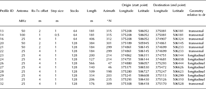
Given the experimental nature of this work, three pulseEKKO PRO GPR antennas with different centre frequencies (25, 50 and 100 MHz) were tested in order to provide different penetration depths and resolution levels. A differential GPS (DGPS) was used concurrently during the GPR acquisition, thus ensuring maximum horizontal and vertical accuracy of the profiles, which is essential to correct the GPR for the topography and to accurately locate the GPR profiles on topographic maps and digital terrain models. A total of 14 profiles were acquired using different GPR antennas, covering a total length of 3.4 km Table 1. GPR profiles were acquired along drumlin longitudinal and transverse axes (Fig. 2), with multiple profiles ideally intersecting each other in order to determine the internal geometry.
Details of the 14 GPR profiles acquired, including the type of antenna used, the length and azimuth of the profiles, and the coordinates (according to the British National Grid system) of their start and end points
The radar data were processed using the following basic steps, with variations for different antenna frequencies.
-
1. A time zero correction was applied to account for the delay caused by the antenna separation. For some lines this w as a constant correction, but for others the correction varied by between 5% and 10% due to the presence of grass tussocks or heather, which meant that it was difficult to keep the antenna spacing constant and aligned exactly parallel.
-
2. Next a background removal step was applied to suppress the high-amplitude direct wave, which travels through the air between the transmitting and receiving antennas.
-
3. A bandpass filter was applied to suppress low-frequency amplifier saturation effects and high-frequency noise.
-
4. A gain correction was made to compensate for the spherical spreading of the radar wave, which causes a reduction of reflection strength with depth.
-
5. A number of profiles displayed a horizontal reverberative noise, which was more common over rough ground with higher vegetation. This may be due to the antennas not being closely coupled to the surface, resulting in ringing between the body of the antenna and the ground. This noise was removed by the application of a horizontal filter.
-
6. The data were migrated using a constant radar wave speed of 0.1 m ns–1. Owing to the variable penetration achieved and the undulating subsurface, a successful common-midpoint (CMP) survey was not possible. However, given the explorative nature of this study and our focus on the relative surface geometry, a mid-range value for sediments (Reference Davis and AnnanDavis and Annan, 1989) was adopted.
The profiles were converted from two-way travel time to depth using the same constant wave speed used for the migration step; the depth scale on the figures is therefore an approximation only.
3. Results
Seven of the fourteen profiles resulted in particularly good-quality images of the subsurface and are presented below. These are profiles 13, 14, 16, 20, 21, 22 and 26 Table 1. The remaining seven profiles were of poorer quality, either because the acquisition parameters were not ideal, or they were heavily impacted by the presence of nearby walls and roads, and by perched water tables (especially in the inter-drumlin areas).
3.1. Drumlin/substrate relationship
A number of transverse and longitudinal profiles were acquired along lines beginning at a bedrock outcrop, with the intent of elucidating the geometry of the drumlin–bedrock contact. On these profiles (Figs 4 and 5) bedrock can be easily recognized by the strong bedding plane reflectors and can be traced for some tens of metres below the drumlins. Structural measurements from the limited outcrops allowed calculation of the apparent dip that would be seen in a section at either end of GPR profiles 20 and 21 (Fig. 4). This gives a range of 4–6° dipping to the northwest. The apparent dip measured from the GPR profiles is 6°, thus supporting our interpretation that these strong reflectors are bedrock bedding planes, and confirming that bedrock can be identified in this type of terrain with the use of appropriate GPR antennas and processing. However, signal attenuation is still an issue where sediment is thick, in this instance >15 m. Thus, bedrock was not imaged below the central portion of the drumlins, although it is clearly visible around the margins in both cross and longitudinal profiles.
GPR profiles 20 and 21 (a), acquired along a line transverse to the main drumlins axis, and a sketched superimposed interpretation (b). The number associated with an arrow along the distance (horizontal) axis of the profiles refers to the intersection with other GPR profiles (see Fig. 2).

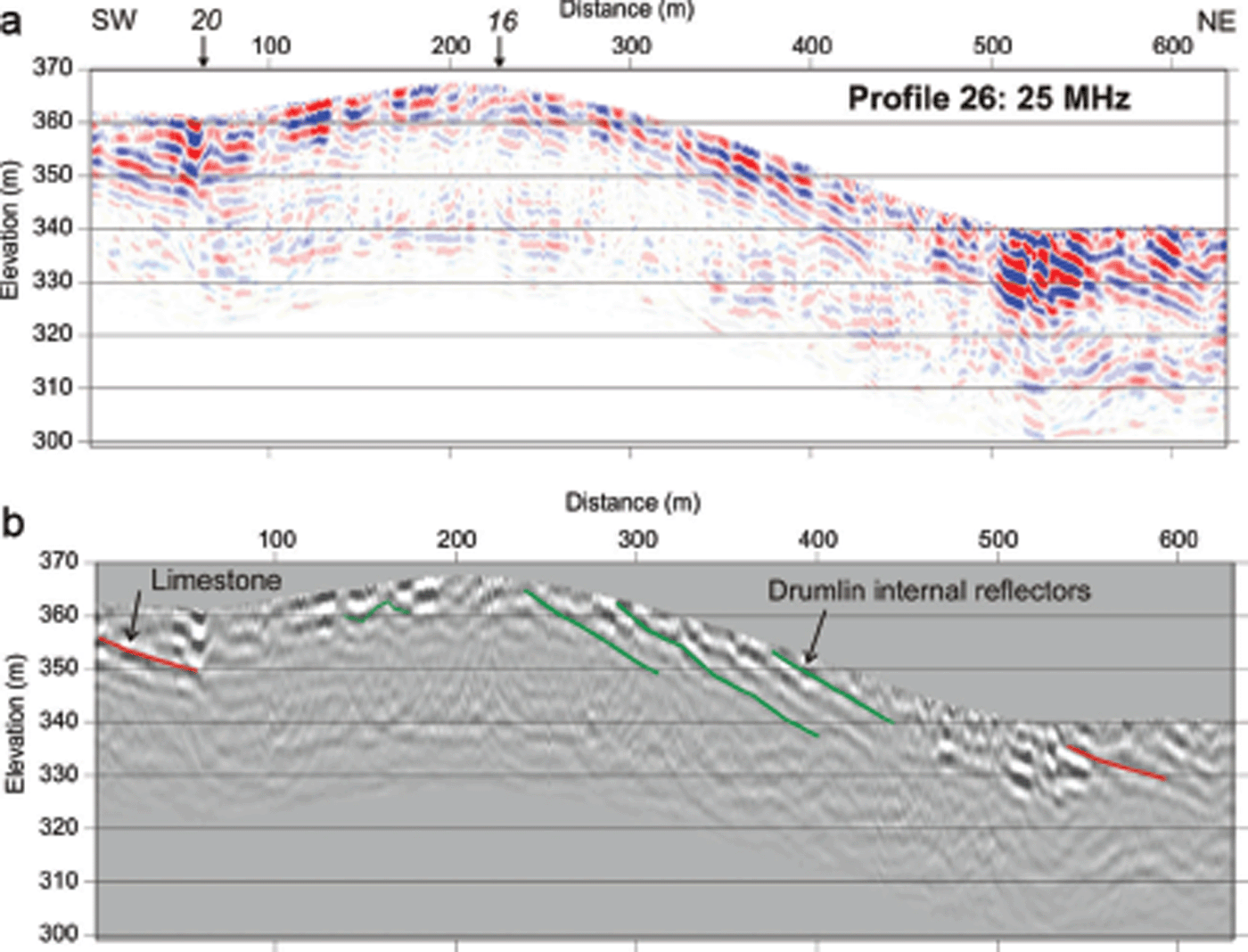
GPR profile 26 (a), acquired along the main drumlin axis, and a sketched superimposed interpretation (b). The number associated with an arrow along the distance (horizontal) axis of the profile refers to the intersection with other GPR profiles (see Fig. 2).
3.2. Inter-drumlin areas
GPR profiles reveal that inter-drumlin areas are characterized by a body of sediment (in terms of radar characteristics) different from that which forms the drumlins (Fig. 6). In particular, inter-drumlin sediment displays horizontal layering that onlaps onto the drumlins and the underlying bedrock. The inter-drumlin sediment is characterized by an overall wedge-like geometry and horizontal layering, and is interpreted as postglacial sediment reworking and infilling of the topographical lows located around the drumlin flanks.
Enlarged image from transverse profile 21 showing details of the inter-drumlin areas (a), and a sketched interpretation (b).

3.3. Drumlin internal architecture
Only one drumlin was investigated in detail using multiple GPR profiles along and across the main axes (Figs 2, 4 and 5). Despite limited penetration, the various GPR profiles reveal important information regarding the architecture of the drumlin. In particular, following the longitudinal profile (Fig. 5), it appears that the sediment in the lee portion of the drumlin comprises a series of downflow-dipping layers. The dip angle of the internal layers is greater than both the surface slope of the drumlin and the dip of the limestone substrata. This is interpreted as evidence for progressive accumulation of sediment in the lee side, while the stoss side is characterized by non-structured sediments (as evinced by a chaotic radar facies), an arrangement that resembles that of a lee-side cavity infill (e.g. Reference Dardis and HanveyDardis and Hanvey, 1994).
3.4. Geophysical acquisition comparison: antenna frequency and stacking interval
In order to determine the optimum acquisition parameters for the GPR survey, several profiles were measured multiple times using different acquisition configurations. In this section we present and compare the repeat profiles.
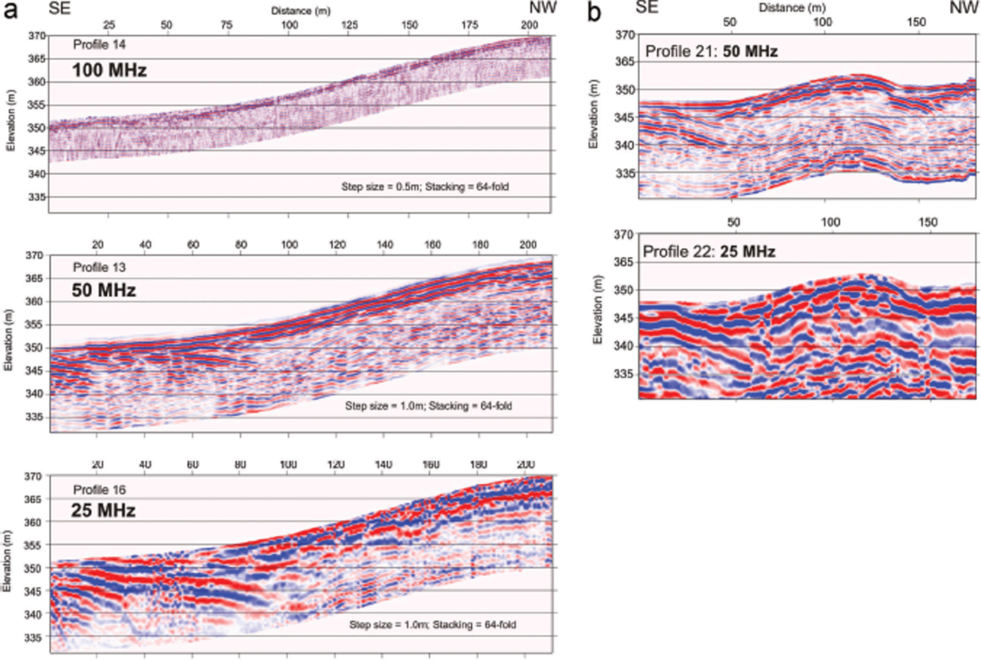
Profiles 13, 14 and 16 were all recorded on the southeastern flank of the central drumlin (Fig. 2). They cover a 181 m section, from a small outcrop of limestone to the crest of the drumlin, with an elevation change of 18 m. This is an optimal situation where the interface between two very different materials, the sediments comprising the drumlin/inter-drumlin areas and the limestone bedrock, should have very different radar responses. Also, the bedrock structure can be determined from exposures and used to fingerprint the bedrock reflectors imaged beneath the drumlin.
Profile 14 (Fig. 7b) was recorded using 100 MHz antennas, with a separation of 1 m, nominal trace spacing of 0.5 m and 64-fold vertical stack (i.e. 64 individual records were made at each location and added together to enhance the signal and suppress the noise). This configuration failed to produce useful results in this setting due to poor signal penetration, and the sediment–bedrock interface cannot be imaged through sediment exceeding 2 m thickness.
Profile 13 was recorded with 50 MHz antennas, with a separation of 2 m, nominal trace spacing of 1 m and 64-fold vertical stack. This profile shows a strong reflection dipping left to right between trace numbers 1 and 90, similar to profile 20 (Fig. 4). Bearing in mind that the profiles started at a bedrock outcrop, the dipping reflectors are interpreted as the sediment–bedrock interface and bedding planes. Another reflection, the nature of which requires further investigation, dips from right to left between trace 100 and 140 and between 6 and 12 m below the surface.
Profile 16 was recorded with 25 MHz antennas, with a separation of 4 m, nominal trace spacing of 1 m and 64-fold vertical stack. This profile also shows a strong reflection where the bedrock is expected to dip beneath the drumlin. The reflection has good lateral continuity but, in common with all other reflections on the record, it is highly reverberative, which makes it more difficult to determine the location of the sediment–bedrock interface.
It is clear from these three profiles that, in this particular setting, the best compromise between penetration and resolution was the 50 MHz antenna. Further confirmation of this is provided by comparison between profiles 21 and 22 (Fig. 7b). These were acquired as cross-lines over the westernmost drumlin (Fig. 2). The acquisition parameters were the same as lines 14 (50 MHz) and 16 (25 MHz) except that the vertical stacking was 128-fold. The additional stacking produces records with an even higher signal-to-noise ratio, so that the bedrock–sediment interface and internal reflectors are clearer. However, acquisition time is longer. This was not a major issue for the manual data collection procedure used in this study, but it may be more problematic if a vehicle-mounted/-towed operation was planned.
A series of repeat profiles used to compare and test different acquisition parameters: GPR profiles (a) 14, 13 and 16 (part) and (b) 21 and 22.
4. Discussion
Digital terrain models and satellite images have become invaluable tools for investigating drumlin morphometry at unprecedented scales, generating datasets of tens of thousands of landforms. Two recent publications (Reference MenziesKulessa and others, 2007; Reference Hiemstra, Kulessa, King and NtarlagiannisHiemstra and others, 2011) suggest that geophysics has the potential to provide information about the internal properties of drumlins. The research is in its infancy and further feasibility tests are needed before any of the techniques can be applied to larger-scale studies that encompass many tens to hundreds of landforms. This work shows results from the deployment of a GPR in order to image drumlins and better understand the nature and geometry of the sedimentary architecture and relationship with the underlying substrate.
Overall, the results are very encouraging and all three objectives outlined in Section 1 were, at least in part, achieved. With a significant penetration depth (>12 m based on the adopted velocity model), GPR was able to shed light on the geometry of the contact between sediment and bedrock substrate, as well as the internal architecture of drumlins and inter-drumlin areas. In particular, this work revealed that the sediment–landform assemblage has three main components: the drumlinized diamict, the bedrock substrate and the inter-drumlin infill. Wherever the bed-forms were imaged, no intermediate sediment between the drumlinized diamict and the bedrock substrate was detected, thus suggesting that the entire volume of available sediment in the system was involved in the drumlinization process. Given the small number of landforms analysed here, our results are unable to elucidate the drumlin-forming process as a whole. However, their interpretation still provides a valid contribution to the wider discussion on drumlin formation. Additionally, it helps to refine future plans for more ambitious geophysical investigations and so warrants some discussion.
4.1. Drumlin/substrate relationship
The contact between the diamict and the bedrock substrate could not be traced continuously beneath the drumlins. However, the GPR was able to image the bedrock around the periphery of drumlins (Fig. 4) and to show, at least in one case, that drumlin sediment structures (lee-side reflectors) could be traced down to a depth that corresponds to at least 75% of the drumlin maximum height (Fig. 5).
The presence of a bedrock protuberance within the body of drumlins has often been suggested as a possible mechanism for the seeding of drumlins (e.g. Reference Boulton, Menzies and RoseBoulton, 1987; Reference Boyce and EylesBoyce and Eyles, 1991). If the drumlins studied here have formed around a bedrock protuberance (e.g. the rock-cored drumlins described by Reference Tavast, Wysota and PiotrowskiTavast, 2001), this must be located in the central portion of the landform, away from its flanks or stoss and lee extremities, contrary to what has been reported previously (Reference Stokes, Spagnolo and ClarkStokes and others, 2011, and references therein).
4.2. Inter-drumlin areas
Contrary to the notion of drumlins as ‘half-eggs’ superimposed on a flat(-tish) landscape (for a thorough discussion see Reference Spagnolo and ClarkSpagnolo and others, 2012), this study shows that drumlin profiles continue below the flat surface that we typically see in inter-drumlin areas. However, both across-flow and along-flow GPR profiles do not reveal a perfectly sinusoidal surface, as the smoothness of the waveform appears truncated by the bedrock in the inter-drumlins areas. This is in apparent contradiction of the initial expectations of the instability theory of drumlin formation, which regards drumlins as waveforms composed of diamict (Reference HindmarshHindmarsh, 1998; Reference Fowler, Maltman, Hubbard and HambreyFowler, 2000). However, further development of this theory is now suggesting the possibility that the original waveforms could progressively migrate downward until reaching the bedrock (fig. 11 of Reference ClarkClark, 2010; Fig. 4 of Reference Stokes, Fowler, Clark, Hindmarsh and SpagnoloStokes and others, 2013).
The exact nature of the inter-drumlin sediment infill has not been investigated directly. However, the frequent presence of standing water in these areas suggests that these sediments are likely to be fine-grained (clay-rich), which favours the formation of perched water tables and fits with a postglacial reworking origin (preferential slope wash and eluviation of the fine fraction). This is confirmed by the occurrence of bog/mire deposits in boreholes from other inter-drumlin areas within the same flowset (British Geological Survey borehole records). A key consequence of the presence of a sediment infill in the inter-drumlin areas is that drumlin height must usually be underestimated. From the results presented here, the apparent drumlin height (measured relative to the modern land surface) would have returned a value 10% lower than the actual drumlin height (measured relative to the base of the inter-drumlin infill). This issue, described theoretically by Reference Spagnolo and ClarkSpagnolo and others (2012), has recently been confirmed by the study of boreholes in a drumlinized terrain in Scotland, where the actual heights of drumlins were up to 20% higher than those simply measured relative to the modern land surface (Reference FinlaysonFinlayson, 2013).
4.3. Drumlin internal architecture
The internal composition and geometry of drumlins could not be elucidated entirely by the GPR investigations, as the GPR signal likely did not reach the bottom of the landforms, especially in their central thickest portion. However, the top 12 m of drumlinized diamict exhibits a distinct arrangement of the sediment along the drumlin’s longitudinal axis. This is evident in all GPR profiles (23, 26 and 29) acquired along the longitudinal axis of drumlins, and can best be illustrated by looking at profile 26 (Fig. 5), where the quality of the data is highest. Here the drumlin sediments display a relatively chaotic (non-layered) stoss side and a more organized layered architecture in the lee side (Fig. 5), revealed by a series of downflow-dipping reflectors. This situation has been described before, both empirically (Reference DardisDardis, 1985; Reference Hanvey, Menzies and RoseHanvey, 1987; Reference Dardis and HanveyDardis and Hanvey, 1994) and theoretically (Reference FowlerFowler, 2009); it could indicate that this drumlin was formed by the presence of (1) a body of harder/frozen/less dilatant/deformable sediment upstream (e.g. Reference Smalley and UnwinSmalley and Unwin, 1968; Reference BaranowskiBaranowski, 1977; Reference Boulton, Menzies and RoseBoulton, 1987) with (2) lee-side deposition in the downstream pressure shadow (e.g. Reference Dardis, Cabe and MitchellDardis and others, 1984).
4.4. Technical issues and recommendations
In this study, the GPR signal was attenuated, disturbed or completely absorbed by the presence of clay in the drumlinized diamict, nearby walls and roads, and perched water tables, respectively. It is recommended that future research should explore multiple acquisition parameters, identifying the most suitable ones in order to minimize each of these limiting factors. A careful selection of the site to be investigated is also crucial. Future research should focus on areas where the diamict is known or at least expected to be sandy with a low clay content. Roads and especially walls/wire fences are also hard to avoid in Britain’s parcelled pasture land, and moving away from these anthropogenic environments often translates into a much rougher terrain with taller vegetation, thus introducing new problems and biases to the acquisition and analysis. Drumlins in countries where farmland is less subdivided would certainly provide a better target. Regions characterized by a dry climate or dry season would also be ideal in order to minimize ground-water. However, despite the fieldwork for this project taking place during an unusually wet May in Cumbria, our results are extremely encouraging as they demonstrate that, despite the heavy rain, only the inter-drumlin areas were completely saturated. The careful selection of a site with permeable substrate, facilitating rapid drainage, clearly assisted in improving the quality of the data acquired.
On the basis of the results presented in Section 3.4, our recommended acquisition parameters for GPR survey of this drumlin set are 50 MHz antennas, with a separation of 1 m, trace spacing of 1 m and 128-fold vertical stack. It should be noted that this conclusion was reached after careful postprocessing following the field campaign. In the field, the 25 MHz records were assessed to be the best on the basis of examining the acquisition screen of the system and also following minimal post-acquisition processing. We therefore recommend that any GPR investigation of drumlin internal architecture includes a testing phase that involves full post-processing of data collected using multiple frequencies and high-resolution display of the results, before the final acquisition parameters are chosen. If a suitable landscape can be identified (e.g. lacking walls, fences and roads, with short vegetation, ideally pasture) a vehicle-towed system could allow rapid data collection across large areas. This will provide the opportunity to characterize the true drumlin geometry (e.g. blister vs waveform, or something else), interaction with the sub-drumlin bed (e.g. bedrock or pre-existing sediments) and the internal architecture of many tens to hundreds of drumlins. Such a dataset will allow much more rigorous testing of drumlin formation theories and improved understanding of the likely implications for ice dynamics.
5. Conclusions
A set of five drumlins in the Eden Valley were investigated by surveying 14 GPR profiles along and across these bedforms using different GPR acquisition configurations. Results indicate that GPR can be successfully employed to image the relationship between the drumlins and their substrate, as well as the drumlin and inter-drumlin sedimentary architecture. Specifically in this setting:
-
1. drumlinized diamict is in direct erosional contact with the bedrock
-
2. there is no evidence of a rock core at either the stoss or lee extremities
-
3. the inter-drumlin areas are characterized by a post-drumlinization (likely post-deglaciation) infill of sediment that masks part of the original drumlin surface profile
-
4. a down-dipping layered structure is present in the lee-side pressure shadow with a non-layered stoss side
-
5. the ideal acquisition parameters were a 50 MHz antenna, with a separation of 1 m, trace spacing of 1 m and 128-fold vertical stack.
Future investigation should focus on situations with: (1) similarly permeable and shallow bedrock conditions but in a less anthropogenically modified terrain (no roads, wires or walls); (2) better antecedent weather conditions (a period of dry weather before the GPR acquisition); (3) sand-and silt-dominated diamict; and (4) a preliminary acquisition with full post-processing phase, run prior to conducting the main GPR campaign, in order to determine the best antenna frequency and acquisition parameters. The ambition should be to apply GPR survey over transects of tens of kilometres and hundreds of drumlins such that the generality of drumlin architecture and its relation to the substrate can be established, removing the restriction of sweeping inferences being drawn from small samples.
Acknowledgements
We thank the editor, Bernd Kulessa, for his review and support, and John Hiemstra and an anonymous reviewer for helpful comments and suggestions. This work was supported by an equipment loan from the UK Natural Environment Research Council (NERC) Geophysical Equipment Facility (Loan 990) and a University of Aberdeen, College of Physical Sciences’ Research and Teaching Enhancement Fund. All authors are indebted to the NERC Geophysical Equipment Facility staff for training in the use of the antennas and GPS. J.C.E. thanks the Denisons for funding his PhD. We also thank Wharton Hall and Shaw Paddock farms for access to the field sites.


 Open access

