

Introduction
Cellular biology provides many examples of filamentous nanomaterials in which control of higher-order structure enables emergent function. Extracellular protein filaments (e.g. pili, flagella, secretory needles and tubes) (Egelman, Reference Egelman2017) and filamentous phage and viruses (Stubbs and Kendall, Reference Stubbs and Kendall2012) represent protein and nucleo-protein assemblies, respectively, in which regulated fabrication from the macromolecular components has led to the evolution of complex function. These extracellular filaments perform a diverse range of functions that would be desirable to emulate in synthetic systems, including chemo-mechanical energy transduction (Poweleit et al., Reference Poweleit, Ge, Nguyen, Loo, Gunsalus and Zhou2016; Wang et al., Reference Wang, Burrage, Postel, Clark, Orlova, Sundberg, Kearns and Egelman2017), controlled delivery (Loquet et al., Reference Loquet, Sgourakis, Gupta, Giller, Riedel, Goosmann, Griesinger, Kolbe, Baker, Becker and Lange2012; Costa et al., Reference Costa, Ilangovan, Ukleja, Redzej, Santini, Smith, Egelman and Waksman2016), selective and tunable catalysis (Lynch et al., Reference Lynch, Hicks, Shepherd, Endrizzi, Maker, Hansen, Barry, Gitai, Baldwin and Kollman2017, Reference Lynch, Kollman and Webb2020), and, as recently discovered, electron transfer over multi-micron length scales (Wang et al., Reference Wang, Gu, O'Brien, Yi, Yalcin, Srikanth, Shen, Vu, Ing, Hochbaum, Egelman and Malvankar2019). While many synthetic peptide and protein filaments have been proposed as substrates for directed applications in medicine and nanotechnology, the limited availability of structural information at high resolution has hindered the development of these assemblies as functional materials (Haines-Butterick et al., Reference Haines-Butterick, Rajagopal, Branco, Salick, Rughani, Pilarz, Lamm, Pochan and Schneider2007; Yan et al., Reference Yan, Nykanen, Ruokolainen, Farrar, Gough, Saiani and Miller2008; Moore and Hartgerink, Reference Moore and Hartgerink2017; Wu et al., Reference Wu, Norberg, Reap, Congdon, Fries, Kelly, Sampson, Conticello and Collier2017; Gelain et al., Reference Gelain, Luo and Zhang2020).
The key to understanding and emulating the diverse functions of protein filaments resides in the ability to deconvolute the structural principles that enable their highly specific assembly. Native protein and nucleoprotein filaments achieve this specificity through a combination of structural control of interactions at protein–protein interfaces within the assembly and spatiotemporal regulation of the post-synthetic processing of the protein subunits into structurally defined filaments. The latter process enables controlled fabrication of the corresponding protein or nucleoprotein filaments but lies beyond our current capabilities to replicate in vitro for synthetic assemblies. In contrast to the majority of synthetic peptide and protein filaments that have been studied in vitro, biologically derived protein filaments often do not self-assemble, but instead the protomers are fabricated into ‘assembled’ structures under conditions that are far from equilibrium (Costa et al., Reference Costa, Felisberto-Rodrigues, Meir, Prevost, Redzej, Trokter and Waksman2015).
Synthetic peptide and protein filaments, while differing in the mechanism of formation from native biological assemblies, display similarities in supramolecular structure. Both classes of filaments are based on non-covalent self-association of subunits (protomers) into high aspect-ratio supramolecular polymers (⩾1 μm in length) that display helical symmetry (Fig. 1). This simple symmetry operation involves rotation through a characteristic helical twist or azimuthal angle (ϕ) with a commensurate axial translation (z). Continuous application of this symmetry operation upon successive addition of protomers generates a filamentous assembly, that is, a helical filament or tube. Such filaments can be generated from protomers having any possible molecular structure as long as sufficient interfacial interactions between subunits are present that stabilize the filament vis-à-vis monomers or discrete oligomers. Within these simple geometrical constraints, an infinite number of structural variations are possible that involve different helical symmetries, as well as superimposed rotational and dihedral symmetry. Helical assemblies are usually characterized in terms of the number of subunits per helical turn, N (=2π/ϕ), and the helical pitch, P (=Nz). In non-rotationally symmetric cases, i.e. C 1 symmetry, these parameters can be determined from assignment of the 1-start helix, i.e. the helix that passes through every subunit in the assembly (Fig. 1). For helical assemblies containing a rotational symmetry axis Cn, the helical symmetry can be understood in terms of the rise and rotation of the n-start helices subject to this rotational symmetry element.
(a) Top and side projections of a helical polymer in which each dot represents an asymmetric unit of the corresponding assembly. (b) Helical net diagram corresponding to the symmetry of the helical polymer. A solid line connects protomers within the 1-start helix of the assembly. (c) Power spectrum derived from the amplitudes of the Fourier transform of this helical polymer in which layer lines are indicated corresponding to pitch (P) and rise (z) in reciprocal space. From S. A. Fromm and C. Sachse (2016)Methods in Enzymology, 579, 307–328, Academic Press Inc. Reprinted with permission from Elsevier.
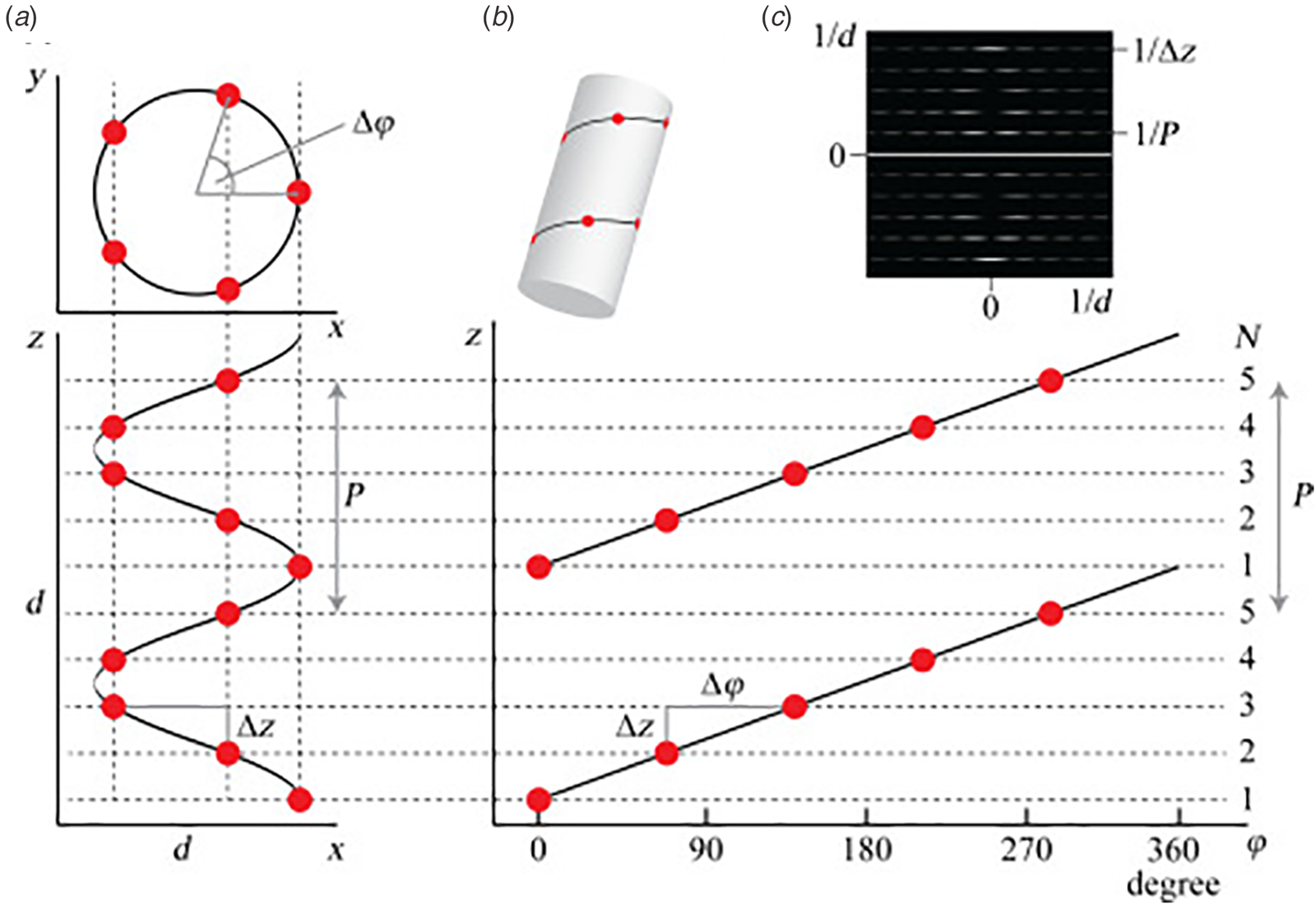
Helical symmetry can be best understood from consideration of the corresponding helical net diagram, in which the helix is unrolled in two dimensions with the axial rise, z, as the ordinate and the azimuthal angle, ϕ, as the abscissa (Fig. 1b). The perspective is usually presented from the outside of the helical assembly and is critical to identification of the helical hand, i.e. right-handed versus left-handed screw sense, of the respective n-start helices. Each n-start helix passes through every nth protomer in the helical assembly.
The 1-start helix (solid line in the helical net of Fig. 1b) is right-handed since the axial rise increases from left to right in the helical net diagram. In contrast, the same helical net diagram indicates the presence of five 5-start helices within the same assembly, which pass through different sets of subunits at a frequency of every fifth protomer. The 5-start helices are left-handed due to an opposite right-to-left inclination in the helical net diagram. Helical symmetry can be determined from analysis of the averaged power spectrum of the filaments (Fig. 1c) (Wang et al., Reference Wang, Yu, Yip, Strynadka and Egelman2006; Egelman, Reference Egelman2010, Reference Egelman2014), which is derived from the Fourier transform of filament segments that are present in the projection images from electron microscopy (EM). The Fourier transform is complex (having both amplitudes and phases), while the power spectrum is simply the intensities (squared amplitudes) of the Fourier transform. As a result, the individual power spectra from each segment can be added together without any need for alignment. The layer lines within the averaged power spectrum correspond to repeat spacings in reciprocal space associated with the spatial frequencies of the different n-start helices that are present within the assembly. To assign helical symmetry, two independent orders, n, of the corresponding Bessel functions must be assigned to sets of observed layer lines in the averaged power spectrum. This process often relies on a trial-and-error approach in which multiple different helical symmetries are assessed as workable solutions. The details of structural determination using cryo-EM image analysis are beyond the scope of this article. However, a recent review highlights the critical considerations involved in assignment of helical symmetry in the structural analysis of synthetic peptide filaments (Wang et al., Reference Wang, Gnewou, Solemanifar, Conticello and Egelman2022).
Prior structural analyses of peptide and protein filaments suggest that helical symmetry can be labile in structural space (Egelman et al., Reference Egelman, Xu, Dimaio, Magnotti, Modlin, Yu, Wright, Baker and Conticello2015; Lu et al., Reference Lu, Li, Yin, Ruan, Yu, Egelman and Wu2015; Wang et al., Reference Wang, Gnewou, Modlin, Beltran, Xu, Su, Juneja, Grigoryan, Egelman and Conticello2021a). Small changes in packing at the protomer interfaces within the assembly can result in different helical symmetries, even under conditions in which the individual protomer structures are highly conserved. For example, filamentous bacteriophages comprise two distinct structural families that display C 5 and C 1 symmetry, respectively, for the helical arrangement of capsid proteins around the single-stranded DNA genome (Marvin et al., Reference Marvin, Symmons and Straus2014). Helical reconstruction from high-resolution cryo-EM image analysis enabled structural determination of assemblies from representative members of these two classes of filamentous bacteriophage, IKe (C 5) and Pf4 (C 1), at near-atomic resolution (NAR) (Xu et al., Reference Xu, Dayan, Goldbourt and Xiang2019; Tarafder et al., Reference Tarafder, Von Kügelgen, Mellul, Schulze, Aarts and Bharat2020). Comparison of the two structures is illustrative of the challenges encountered in the structural analysis of filamentous assemblies. The capsid assemblies consist of simple α-helical protomers. Superimposition of individual protomers derived from the two structures indicated a backbone root-mean-square deviation of ca. 1.5 Å despite low sequence similarity. Since the side-chain interactions define the protein–protein interfaces within the respective assemblies, the differences in higher-order structure presumably result from differences in sequence since the protomer fold is conserved.
The structures of the corresponding helical assemblies of the IKe and Pf4 phage capsids are depicted in Fig. 2 at 3.4 Å (PDB: 6A7F) and 3.2 Å (PDB: 6TUQ) resolution, respectively. In each case, the capsid proteins are arranged in a similar orientation around the central axis of the assembly. Single protofilaments are highlighted in red within the assembly. For phage IKe, the highlighted protofilament coincides with one of the right-handed 10-start helices under C 5 symmetry. In contrast, under the different symmetry of phage Pf4 capsid, the protofilaments coincide with the right-handed 11-start helices.
Side (a) and top (b) views of the atomic model of the phage IKe capsid. Side (c) and top (d) views of the atomic model of the phage Pf4 capsid. Single protofilaments corresponding to the 10-start and 11-start helices of the IKe and Pf4 capsids, respectively, are highlighted in red.

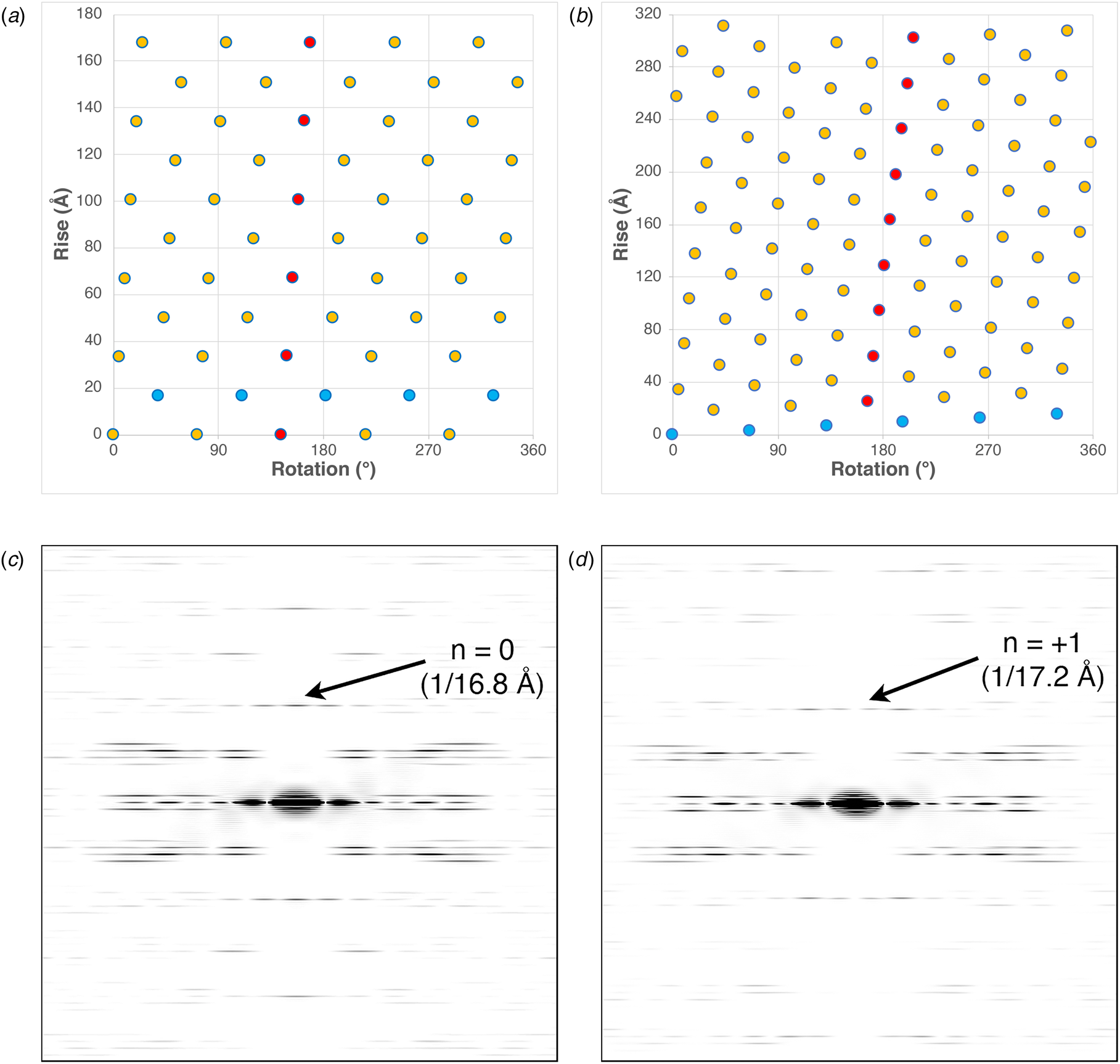
These differences can be most easily visualized through a comparison of the respective helical net diagrams. The structural subunits associated with the respective protofilaments are highlighted in red (Fig. 3a and b). For phage IKe, a representative set of protomers related through the C 5 rotational axis is depicted in cyan. Similarly, the right-handed 1-start helix of phage Pf4 is highlighted in the corresponding helical net. Figure 3c and d depicts a section of calculated power spectra of the respective assemblies, initially sampled at a frequency of 2 Å pixel−1. Arrows indicate the spatial frequencies associated with the axial rise corresponding to the meridional (n = 0) for IKe and the 1-start helix (n = +1) for Pf4. In either case, the corresponding axial repeats are quite similar between the two assemblies despite the differences in helical symmetry.
(a) Helical net diagram of IKe phage. (b) Helical net diagram of Pf4 prophage. (c) Calculated power spectrum of IKe phage. (d) Calculated power spectrum of Pf4 phage.
In this review, the term ‘helical assemblies’ describes supramolecular polymers of proteins, peptides, and structurally related synthetic foldamers that display helical symmetry. This symmetry operation can be applied to protomers based on any structural motif as long as the interfaces between subunits are stable under the set of experimental conditions under which self-assembly occurs. These assemblies need not form closed cylindrical structures, i.e. assemblies in which successive turns of the helix make physical contact through an axial interface. The latter structures are often denoted as nanotubes since self-association generates a water-filled central cavity (lumen) that runs through the structure and is oriented parallel to the helical axis (Bong et al., Reference Bong, Clark, Granja and Ghadiri2001; Hamley, Reference Hamley2014). Peptide nanotubes can also result from other modes of self-assembly, e.g. axial stacking of cyclic peptides (Ghadiri et al., Reference Ghadiri, Granja, Milligan, Mcree and Khazanovich1993; Insua and Montenegro, Reference Insua and Montenegro2020). The latter subject has been reviewed recently and will not be covered here (Song et al., Reference Song, Cheng, Kariuki, Hall, Hill, Rho and Perrier2021).
This review will discuss the structure of biomimetic helical assemblies derived from synthetic peptides and peptido-mimetics. Where possible, we focus on helical assemblies in which the structures have been solved at high resolution using biophysical methods such as single-crystal diffraction, solid-state nuclear magnetic resonance (ssNMR) spectroscopic measurements, or helical reconstruction from cryo-EM. Such NAR methods for structural determination have revolutionized the study of helical assemblies. These techniques afford atomic models that provide structural insights into the interfacial packing interactions between protomers that guide the formation of these helical assemblies. The information gleaned from structural studies of biological helical assemblies has led to the emergence of a research field focusing on the design of biomimetic helical assemblies from synthetic peptides and structurally related foldamers (i.e. peptido-mimetic oligomers). The goal of the latter studies is to recapture the complex function and responsive behavior of biologically derived helical assemblies using simple structural motifs that are amenable to synthetic control.
The initial discussion will focus on an introduction to high-resolution methods for structural analysis of helical assemblies in conjunction with their relative merits and limitations. Subsequently, different classes of helical assemblies will be discussed in terms of the conformational features of the protomers. In each case, we will refer to specific examples of helical filaments that have been characterized to NAR.
A recurrent theme in the field of designed filamentous assemblies is the plasticity of quaternary structure in sequence space (Egelman et al., Reference Egelman, Xu, Dimaio, Magnotti, Modlin, Yu, Wright, Baker and Conticello2015; Lu et al., Reference Lu, Li, Yin, Ruan, Yu, Egelman and Wu2015). Currently, few high-resolution structural models have been generated for filamentous assemblies of designed peptides or proteins (Kajander et al., Reference Kajander, Cortajarena, Mochrie and Regan2007; Cormier et al., Reference Cormier, Pang, Zimmerman, Zhou and Paravastu2013; Egelman et al., Reference Egelman, Xu, Dimaio, Magnotti, Modlin, Yu, Wright, Baker and Conticello2015; Nagy-Smith et al., Reference Nagy-Smith, Moore, Schneider and Tycko2015, Reference Nagy-Smith, Beltramo, Moore, Tycko, Furst and Schneider2017; Chen et al., Reference Chen, Corro, Le and Nowick2017, Reference Chen, Ing, Wang, Xu, Sloan, Lam, Winter, Egelman, Hochbaum, Clark and Glover2020; Lee et al., Reference Lee, Wang, Makhlynets, Wu, Polizzi, Wu, Gosavi, Stöhr, Korendovych, Degrado and Hong2017; Shen et al., Reference Shen, Fallas, Lynch, Sheffler, Parry, Jannetty, Decarreau, Wagenbach, Vicente, Chen, Wang, Dowling, Oberdorfer, Stewart, Wordeman, De Yoreo, Jacobs-Wagner, Kollman and Baker2018; Zhang et al., Reference Zhang, Huang, Yang, Kratochvil, Lolicato, Liu, Shu, Liu and Degrado2018; Hughes et al., Reference Hughes, Wang, Wang, Kreutzberger, Osinski, Orlova, Wall, Zuo, Egelman and Conticello2019; Feng et al., Reference Feng, Wang, Wang, Oh, Berciu, Cui, Egelman and Xu2020; Wang et al., Reference Wang, Gnewou, Modlin, Beltran, Xu, Su, Juneja, Grigoryan, Egelman and Conticello2021a; Pieri et al., Reference Pieri, Wang, Arteni, Vos, Winter, Le Du, Artzner, Gobeaux, Legrand, Boulard, Bressanelli, Egelman and Paternostre2022). It has been observed that the experimental structures often display significant differences from the conceptual model upon which the initial design was based. Structural polymorphism is commonly observed for synthetic peptide assemblies or native proteins assembled in vitro. The observed structures may depend strongly on the initial conditions, i.e. temperature, pH, ionic strength, etc., that were employed for peptide self-assembly (Close et al., Reference Close, Neumann, Schmidt, Hora, Annamalai, Schmidt, Reif, Schmidt, Grigorieff and Fändrich2018; Guenther et al., Reference Guenther, Ge, Trinh, Sawaya, Cascio, Boyer, Gonen, Zhou and Eisenberg2018; Zhang et al., Reference Zhang, Falcon, Murzin, Fan, Crowther, Goedert and Scheres2019; Wang et al., Reference Wang, Gnewou, Wang, Osinski, Zuo, Egelman and Conticello2021b). In addition, the experimental methods employed to prepare the sample for high-resolution structural analysis, e.g. crystallization, lyophilization, cryo-vitrification, may bias the system toward a particular structural variant (Egelman et al., Reference Egelman, Xu, Dimaio, Magnotti, Modlin, Yu, Wright, Baker and Conticello2015).
Structural characterization of synthetic helical filaments
Structural analysis of helical filaments requires application of experimental methods that interrogate structure across multiple length scales. A number of methods can analyze structure at low resolution and are applicable to relatively rapid screening and analysis of peptide specimens for the presence of ordered conformations and the formation of well-defined supramolecular structure. Circular dichroism (CD) spectropolarimetry and Fourier-transform infrared (FTIR) and Raman spectroscopy can provide evidence for the formation of secondary and tertiary structure, which can be subsequently correlated with self-assembly behavior. Atomic force microscopy (AFM) and conventional transmission electron microscopy (TEM) can reveal the presence of supramolecular structure and provide insight into the morphological features of the resultant assemblies at medium resolution. Small-angle X-ray and neutron scattering measurements, i.e. SAXS and SANS, afford information on the structural features of the assemblies in solution at low-to-medium resolution in the range from 1 to 100 nm from analysis of the form factor scattering (Guilbaud and Saiani, Reference Guilbaud and Saiani2011). AFM and scanning electron microscopy) (SEM) can also be employed for assignment of the helical hand of peptide assemblies for cases in which the chirality of the surface features can be resolved (Wang et al., Reference Wang, Gnewou, Solemanifar, Conticello and Egelman2022). However, only a small set of experimental methods can give information at NAR on filamentous helical assemblies, namely X-ray and electron diffraction methods, ssNMR spectroscopy, and cryo-EM.
NAR structural information is essential for understanding the internal structure of the protomers and the interfacial contacts that stabilize the helical assemblies. The meaning of the term ‘near-atomic resolution’ is a subject of active debate (Chiu et al., Reference Chiu, Holton, Langan, Sauter, Schlichting, Terwilliger, Martin, Read and Wakatsuki2017; Wlodawer and Dauter, Reference Wlodawer and Dauter2017), especially as regards the level of resolution that can be achieved using different methods of structural analysis (Wlodawer et al., Reference Wlodawer, Li and Dauter2017). True atomic resolution, ca. 1.2 Å, refers to the ability to distinguish between separated atoms in an electron density map (Sheldrick, Reference Sheldrick1990; Morris and Bricogne, Reference Morris and Bricogne2003). NAR is less well-defined, but it usually employed to describe the resolution of density maps that can serve as the basis for the construction of reliable atomic models. In this latter case, the resolution limit has been claimed to be as low as ca. 4 Å for the corresponding density maps. The reliability of the corresponding atomic model depends on the map quality, which in turn depends on intrinsic properties of the sample, e.g. the thermodynamic stability of the interfacial interactions between protomers within the assembly. Most peptide and protein filaments are intrinsically flexible. Flexibility can introduce disorder into the sample, which can lower the quality of the density maps resulting from helical reconstruction (Egelman et al., Reference Egelman, Francis and Derosier1982; Orlova and Egelman, Reference Orlova and Egelman1993).
Recent improvements in hardware and software have made the currently available experimental methods for structural determination much more powerful in terms of the limits of resolution and the scope of substrates that can be examined. Until recently, atomic-level structural data could only be obtained on fibrillar assemblies using X-ray diffraction methods (crystallography and fiber diffraction). However, an increasing number of filamentous structures have been solved to NAR using either ssNMR spectroscopic analysis or, more commonly, cryo-EM. In addition, recent developments in microcrystal electron diffraction (MicroED) have enabled a wider application of diffraction methods to protein crystals, especially for situations in which only sub-micron-sized crystals can be obtained as is often the case for peptide filaments (Rodriguez et al., Reference Rodriguez, Ivanova, Sawaya, Cascio, Reyes, Shi, Sangwan, Guenther, Johnson, Zhang, Jiang, Arbing, Nannenga, Hattne, Whitelegge, Brewster, Messerschmidt, Boutet, Sauter, Gonen and Eisenberg2015, Reference Rodriguez, Eisenberg and Gonen2017; Sawaya et al., Reference Sawaya, Rodriguez, Cascio, Collazo, Shi, Reyes, Hattne, Gonen and Eisenberg2016; Warmack et al., Reference Warmack, Boyer, Zee, Richards, Sawaya, Cascio, Gonen, Eisenberg and Clarke2019).
Historically, the application of X-ray fiber diffraction enabled the first structural determinations of filamentous protein assemblies at NAR. However, the necessity of generating highly oriented specimens restricted these analyses to filaments that displayed persistent rod-like structures that promoted mesophase formation, which facilitated alignment of the filaments for diffraction experiments. The most common substrates were rigid filamentous viruses such as tobacco mosaic virus (Namba et al., Reference Namba, Pattanayek and Stubbs1989). Specimens that displayed greater flexibility were less amenable to the formation of highly oriented sols. Given that most helical assemblies fall into the category of flexible or semi-flexible filaments, the utility of fiber diffraction for NAR structural determination of helical assemblies remains limited. Nevertheless, fiber diffraction can provide valuable structural information on peptide assemblies. For example, fiber diffraction of oriented amyloid filaments was critical for the identification of the cross-β conformation (Eanes and Glenner, Reference Eanes and Glenner1968; Sunde et al., Reference Sunde, Serpell, Bartlam, Fraser, Pepys and Blake1997; Diaz-Avalos et al., Reference Diaz-Avalos, Long, Fontano, Balbirnie, Grothe, Eisenberg and Caspar2003).
Single-crystal X-ray diffraction was the first experimental method to be widely applied to the analysis of peptide assemblies at NAR. This technique has been particularly valuable for structural determination of assemblies derived from short amyloidogenic peptide sequences (Eisenberg and Sawaya, Reference Eisenberg and Sawaya2017; Ke et al., Reference Ke, Zhou, Serpell, Riek, Knowles, Lashuel, Gazit, Hamley, Davis, Fändrich, Otzen, Chapman, Dobson, Eisenberg and Mezzenga2020). However, two distinct challenges are encountered in the application of this method. The first is the experimental difficulty associated with growing suitable single crystals, which is a necessity for high-resolution diffraction experiments. Helical assemblies present several unique challenges to crystallization including limited solubility, length variability, and structural polymorphism. High-throughput screening of crystallization conditions has facilitated identification of effective crystallization conditions. However, crystallization of fibrillogenic peptides and proteins seems to work best under conditions in which the protomers are weakly associated such that self-assembly occurs concurrently with crystal growth. Achieving this condition may require introduction of mutations that weaken the interfacial interaction between protomers or enhance the solubility of the peptide or protein (Spencer et al., Reference Spencer, Chen, Manuel and Nowick2013).
The second challenge for single-crystal diffraction analysis is imposition of crystallographic symmetry on the assembly. Helical arrays of chiral rod-like molecules cannot easily accommodate the translational symmetry required for crystallization without imposition of an energy penalty associated with elastic distortion of the protomers (Rodriguez et al., Reference Rodriguez, Ivanova, Sawaya, Cascio, Reyes, Shi, Sangwan, Guenther, Johnson, Zhang, Jiang, Arbing, Nannenga, Hattne, Whitelegge, Brewster, Messerschmidt, Boutet, Sauter, Gonen and Eisenberg2015). The resultant packing frustration can limit the dimensions of the crystals. MicroED methods using cryo-EM have alleviated this problem to a degree by allowing single-crystal diffraction experiments to be performed on sub-micron crystals. In addition, crystallographic space symmetry restricts the screw axes to two-, three-, four-, and six-fold rotations. While other helical symmetries can be accommodated in crystal structures (Dauter and Jaskolski, Reference Dauter and Jaskolski2018), the protomers cannot occupy symmetry-equivalent positions under these non-crystallographic screw axes. In contrast, the structures of peptide and protein filaments can vary over a wide range of helical symmetries that include non-crystallographic screw symmetry and non-integral helical repeats.
The implication of these limitations can be best understood through comparison of peptide and protein filament structures solved using crystallography versus those determined using complementary methods such as ssNMR spectroscopy or cryo-EM, which are not subject to these symmetry restrictions (vide infra). Currently, a number of structures are available at comparable resolution for helical assemblies derived from the same peptide sequence using two independent methods of high-resolution structural analysis. In the limited cases in which these comparisons have been made, the crystallographically determined structures have been observed to differ from those determined from ssNMR or cryo-EM (Guenther et al., Reference Guenther, Ge, Trinh, Sawaya, Cascio, Boyer, Gonen, Zhou and Eisenberg2018; Guerrero-Ferreira et al., Reference Guerrero-Ferreira, Taylor, Mona, Ringler, Lauer, Riek, Britschgi and Stahlberg2018, Reference Guerrero-Ferreira, Taylor, Arteni, Kumari, Mona, Ringler, Britschgi, Lauer, Makky, Verasdonck, Riek, Melki, Meier, Böckmann, Bousset and Stahlberg2019). Crystallization imposes conditions that may select for a specific structural form that happens to crystallize well, while a sample of filaments suspended in solution may display significant structural polymorphism. Despite this caveat, crystallography has yielded significant structural insights into the packing of protomers within peptide and protein assemblies and has been especially important in understanding the structural factors that control association of amyloidogenic peptides that adopt cross-β structures (Eisenberg and Sawaya, Reference Eisenberg and Sawaya2017). In addition to the aforementioned concerns, crystallographic studies of helical filaments often employ mutants or truncations of the native sequences that promote crystallization. The effect of these modifications, vis-à-vis the structure of filaments derived from full-length proteins, needs to be evaluated on an individual basis.
ssNMR measurement has also been applied as a method for structural determination of helical peptide filaments (Huang et al., Reference Huang, Hudson, Gao, Roberts, Paravastu, Nilsson and Doran2018). Similar to solution NMR structural determination of soluble proteins, selective labeling of the protomers with magnetically active nuclei enables determination of inter-atomic distances between labeled residues within the protein sequence. These distance measurements place constraints on the spatial arrangement of the polypeptide backbone and side chains from which a structural model can be generated. The accuracy of the atomic model depends on the number of constraints, the selectivity of labeling, and the size of the protein.
NMR distance measurements have an upper limit that depends on the identity of labeled nuclei and the experimental method. For 13C–15N contacts, the most commonly employed isotopic spin pair in protein and peptide structural determinations, the upper limit for accurate distance measurements is approximately 6 Å. However, inter-atomic distances up to 10–12 Å can be measured using magnetically active nuclei that are less common in peptides and protein sequences, e.g. 19F and 31P (Mehta et al., Reference Mehta, Shayo, Vankayalapati, Hurley and Schaefer2004). Multiple long-range distance constraints can be challenging to acquire, which hinders assignment of helical symmetry and accurate determination of supramolecular structure. To address this issue, ssNMR structural analysis has been combined with scanning transmission electron microscopy (STEM) mass-per-length measurement or cryo-EM imaging (Colvin et al., Reference Colvin, Silvers, Ni, Can, Sergeyev, Rosay, Donovan, Michael, Wall, Linse and Griffin2016).
In addition, the structural polymorphism observed for many helical assemblies can multiply the effective number of resonances in ssNMR experiments, which can complicate structural analysis as it often results in significant spectroscopic overlap and ambiguity in resonance assignment. Therefore, monomorphic filaments represent the best substrates for ssNMR structural analysis, although these may be challenging to isolate and purify to homogeneity due to the intrinsic polymorphism associated with peptide assemblies. Nevertheless, ssNMR methods have been employed for the structural determination of helical assemblies to NAR, including the structures of extended β-sheet filaments such as the HET-s prion domain (Siemer et al., Reference Siemer, Ritter, Ernst, Riek and Meier2005), the Aβ(1-42) amyloid assembly (Colvin et al., Reference Colvin, Silvers, Ni, Can, Sergeyev, Rosay, Donovan, Michael, Wall, Linse and Griffin2016), and the α-synuclein (α-syn) polymeric filament (Heise et al., Reference Heise, Hoyer, Becker, Andronesi, Riedel and Baldus2005).
Historically, TEM has been one of the most important methods for morphological analysis of peptide and protein filaments. The development of cryo-vitrification methods enabled preservation of isolated and dispersed filaments as thin films in the frozen, hydrated state (Dubochet, Reference Dubochet2012). In addition, EM imaging at cryogenic temperatures significantly reduces beam damage due to interaction of the substrate with high-energy electrons. Cryo-EM imaging is less susceptible to introduction of structural artifacts than conventional TEM imaging, which often involves application of a heavy-atom stain (Lepault et al., Reference Lepault, Booy and Dubochet1983). However, until the emergence of direct electron detectors, the lower limit of resolution for cryo-EM structural determination was ~10 Å, which was insufficient to resolve secondary structure elements (Li et al., Reference Li, Mooney, Zheng, Booth, Braunfeld, Gubbens, Agard and Cheng2013; Kühlbrandt, Reference Kühlbrandt2014; Subramaniam et al., Reference Subramaniam, Earl, Falconieri, Milne and Egelman2016). Higher-resolution reconstructions have been performed using film images (Ge and Zhou, Reference Ge and Zhou2011; Sachse, Reference Sachse2015), but this method is labor-intensive and has been superseded by use of direct electron detection cameras with high detective quantum efficiency (Song et al., Reference Song, Lenhart, Flegler, Makbul, Rasmussen and Böttcher2019).
Initially, pseudo-atomic models were built using rigid body modeling of structural subunits into the lower-resolution electron density maps resulting from cryo-EM measurements. The subunit structures were usually determined from X-ray crystallography or solution NMR spectroscopic determinations. These pseudo-atomic models were limited in accuracy due to the incompleteness of individual subunit structures. NMR structures display some degree of disorder in the more flexible regions of the molecule. Crystal structures are often derived from protein fragments rather than the entire peptide sequence. In addition, these input structures often provided little information about the packing interfaces in the helical filament, which are frequently more ordered within the assembly than in the isolated, soluble monomeric precursors.
The development of electron cryo-microscopy with direct electron detection has led to a revolution in structural determination of helical assemblies at NAR (Kühlbrandt, Reference Kühlbrandt2014). These detectors can routinely achieve resolutions ⩽4.0 Å. This level of resolution permits de novo building of atomic models of helical filaments from cryo-EM data alone. The main method for structure analysis of helical filaments involves iterative real-space reconstruction from cryo-EM images (Egelman, Reference Egelman2000, Reference Egelman2007, Reference Egelman2010). This single-particle method enables reconstruction from randomly oriented helical filaments that result from immobilization in a thin film of vitreous ice on a cryo-EM grid. Programs such as Relion and cryoSPARC are available to assist in image processing and reconstruction after assignment of helical symmetry (He and Scheres, Reference He and Scheres2017; Punjani et al., Reference Punjani, Rubinstein, Fleet and Brubaker2017).
Cryo-EM helical reconstruction has many significant advantages for structural analysis of helical assemblies. As a single-particle method, the polymorphism typically observed for helical assemblies can be dealt with through manual or automated classification of the different structural variants. If enough images can be collected, different morphic variants can be structurally analyzed within the same grid. In addition, cryo-EM can tolerate the presence of impurities in the sample as long as the images of the contaminants can be distinguished from those of the analyte (Spaulding et al., Reference Spaulding, Schreiber, Zheng, Dodson, Hazen, Conover, Wang, Svenmarker, Luna-Rico, Francetic, Andersson, Hultgren and Egelman2018). Cryo-EM analysis can be applied to small sample sizes (a few microliters of 0.1–1 mg ml−1 solution) and does not require heavy-atom or isotopic labeling as does crystallographic analysis and NMR measurements, respectively. In addition, the method is amenable to structure determinations on helical filaments directly derived from biological samples available in limited quantity, such as tau filaments from human brain tissue (Scheres et al., Reference Scheres, Zhang, Falcon and Goedert2020) or pili harvested directly from bacterial cells (Egelman, Reference Egelman2017). This procedure precludes the necessity of in vitro assembly of protein filaments, which can often result in structural polymorphism or deviations from the native filament structure (Wang et al., Reference Wang, Yu, Yip, Strynadka and Egelman2006).
Comparison between NAR structures determined using different experimental methods highlights the challenges associated with the structural polymorphism of helical assemblies. Guenther et al. (Reference Guenther, Ge, Trinh, Sawaya, Cascio, Boyer, Gonen, Zhou and Eisenberg2018) characterized the structure that resulted from crystallization of an eleven amino acid, amyloidogenic peptide segment, 247DLIIKGISVHI257, from human TAR DNA-binding protein 43 (TDP-43). MicroED was employed to determine the structure of 247DLIIKGISVHI257 nanocrystals grown at 37 °C in aqueous CHES buffer (pH 8.5) (PDB: 5W52). The resultant structure comprised of a two-fold symmetric filament in which each protofilament displayed a parallel cross-β spine. The two protofilaments interacted through a steric zipper interface in which a face-to-face interaction resulted in side-chain interdigitation.
Surprisingly, at pH values ⩽7.5, cryo-EM analysis of assemblies derived from the same 247DLIIKGISVHI257 peptide segment indicated the presence of a multitude of filamentous structures. Helical reconstruction of the most abundant population of filaments resulted in an atomic model that displayed 32 screw symmetry (PDB: 5W7V) (Guenther et al., Reference Guenther, Ge, Trinh, Sawaya, Cascio, Boyer, Gonen, Zhou and Eisenberg2018). In addition to the observed difference in helical symmetry between the crystal structure and cryo-EM model, the structure of the protein filament observed in the cryo-EM analysis consisted of three protofilaments that were each based on an asymmetric unit composed of nine peptides. The protofilaments corresponded to the left-handed 3-start helices, in which each of the nine 247DLIIKGISVHI257 segments in the asymmetric unit could adopt one of three different possible conformations. This conformational disparity between the crystal structure and cryo-EM structures of 247DLIIKGISVHI25 illustrates a critical consideration in the structural analysis of helical assemblies, namely, the potential plasticity of quaternary structure in sequence space and the dependence of the filament structure on the assembly conditions.
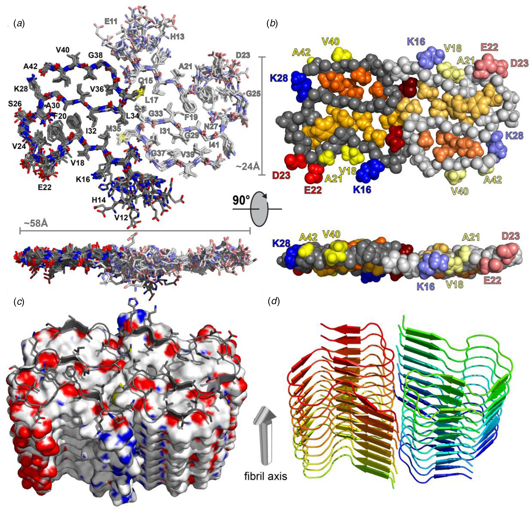
Structural differences have also been observed between atomic models generated for assemblies derived from the same peptide using approaches based on either ssNMR spectroscopy or cryo-EM analysis. Colvin et al. reported the structure of a monomorphic variant of a peptide assembly of Aβ1-42 using distance constraints derived from ssNMR measurements (Colvin et al., Reference Colvin, Silvers, Ni, Can, Sergeyev, Rosay, Donovan, Michael, Wall, Linse and Griffin2016). This peptide has attracted significant scientific interest as it is a primary component of the amyloid fibers associated with the pathology of Alzheimer's disease. The filament structure comprised of an interacting pair of helical assemblies, in which each protofilament displayed the cross-β spine that is typical of amyloid assemblies. Hydrophobic interactions across the mating interface mediated association between protofilaments over an extended interface (Fig. 4).
Dimeric structure of Aβ1-42 as solved by Colvin et al. by ssNMR measurements. Only residues Q15-A42 are shown. (a) Overlay of the 10 lowest-energy NMR structures. Left monomer is shown in dark colors; right monomer is shown in pale colors. (b) CPK model showing backbone in gray, hydrophobic side chains are shown in yellow (solvent-exposed), gold, and orange (buried clusters). (c) Surface model of Aβ1-42. (d) Ribbon model of Aβ1-42. Reprinted with permission from Colvin et al. (Reference Colvin, Silvers, Ni, Can, Sergeyev, Rosay, Donovan, Michael, Wall, Linse and Griffin2016). Journal of the American Chemical Society, 138(30), 9663–9674. DOI: 10.1021/jacs.6b05129. Copyright 2016 American Chemical Society.
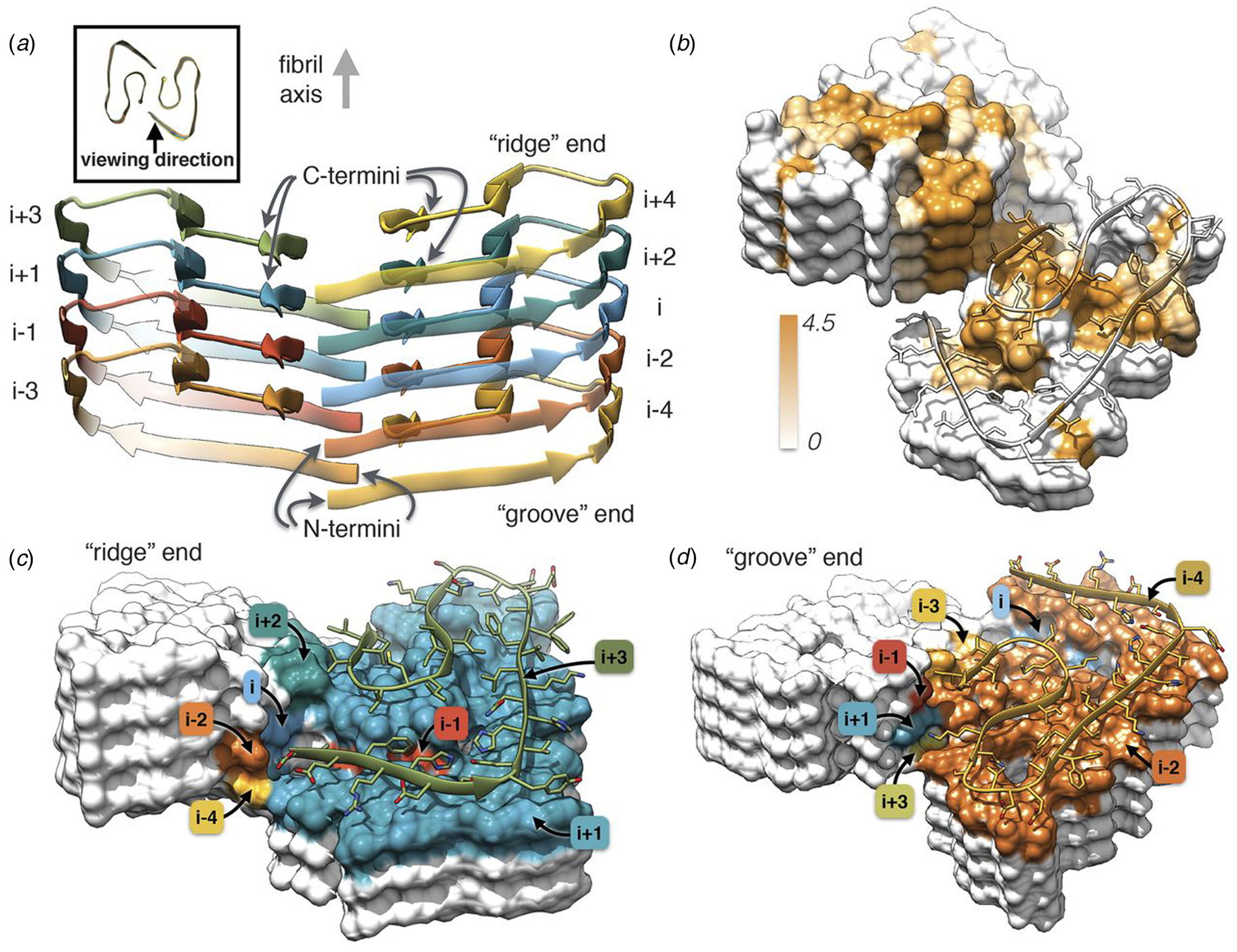
Independently, Gremer et al. employed helical reconstruction from cryo-EM images to build an atomic model of the filament structure for a different monomorphic variant of Aβ1-42 (PDB: 5OQV) (Gremer et al., Reference Gremer, Schölzel, Schenk, Reinartz, Labahn, Ravelli, Tusche, Lopez-Iglesias, Hoyer, Heise, Willbold and Schröder2017). The cryo-EM structure differed significantly in detail from that reported by Colvin et al. The protofilament displayed a dimeric structure in which the two assemblies were related by the pseudo-21 screw axis (Fig. 5) (Scheres, Reference Scheres2020). In addition, a slight left-handed super-helical twist of −1.45° per 4.67 Å axial rise was observed for the protofilament, which resulted in a large helical pitch of circa 1200 Å. The helical reconstruction confirmed both the presence of the cross-β spine within the protofilaments and the steric zipper interactions between protofilaments at the inter-protomer interface. Despite these observations, the details of the packing interaction across the hydrophobic interface and the N-terminal structure of the peptide were distinctly different from the previously reported NMR analysis. The features of the cryo-EM structure were independently confirmed by ssNMR measurements on the corresponding filaments. The two structures represent two distinct morphic variants of Aβ1-42. The experimental conditions for self-assembly differed significantly between the two Aβ1-42 preparations, which reinforces the idea that specimen preparation has a critical influence on the structure of the corresponding filaments.
Dimeric structure of Aβ1-42 as solved by Gremer et al. by cryo-EM with helical reconstruction. (a) Opposing assemblies are staggered, producing a pseudo-21 screw axis in the filament. (b) Surface hydrophobicity of a representative segment the Aβ1-42 peptide filament. Brown represents hydrophobicity value of 4.5, white represents 0.0 according to the Kyte–Doolittle scale. (c, d) Model of the ‘ridge’ and ‘groove’ ends of the Aβ1-42 filament. Colors correspond to layers in (a). From Gremer et al. (Reference Gremer, Schölzel, Schenk, Reinartz, Labahn, Ravelli, Tusche, Lopez-Iglesias, Hoyer, Heise, Willbold and Schröder2017). Science, 358(6359), 116–119. Reprinted with permission from AAAS.
Structures of helical peptide assemblies
The diverse functional properties and exquisite responsive behaviors of biologically derived protein filaments have stimulated interest in the design of synthetic peptide assemblies that mimic the structure and function of the native congeners (Bowerman and Nilsson, Reference Bowerman and Nilsson2012; Hamley, Reference Hamley2014; Beesley and Woolfson, Reference Beesley and Woolfson2019). However, rational and predictive design of helical assemblies remains a significant challenge, primarily due to the lability of helical symmetry in structural space and the resultant potential for structural polymorphism. Through necessity, the design of synthetic peptide filaments has primarily drawn from sequence–structure correlations established from structural analysis of super-secondary and tertiary structures of soluble proteins and discrete oligomers. Several examples of these peptide designs are described in the following sections. However, recent structural evidence suggests this approach may be insufficient to uniquely specify the supramolecular structure of the corresponding filaments. Supramolecular polymerization can result in the formation of helical filaments that display periodic chemical functionality along the contour length of the assembly. The high density of functional groups along the surface of the filaments can often promote self-association into higher-order structures (Wang et al., Reference Wang, Gnewou, Modlin, Beltran, Xu, Su, Juneja, Grigoryan, Egelman and Conticello2021a). The influence of these interactions can be difficult to accurately predict since, in isolation, the energetic contributions of such local interactions to filament stability may be relatively small. In addition, researchers have observed that a small number of directed mutations at surface positions may convert soluble proteins into filamentous assemblies without perturbing the folded structure of the protomer (Garcia-Seisdedos et al., Reference Garcia-Seisdedos, Empereur-Mot, Elad and Levy2017, Reference Garcia-Seisdedos, Villegas and Levy2019). Due to the lability of helical symmetry and the resultant plasticity of quaternary structure, many synthetic peptide filaments display structural heterogeneity, often in conjunction with kinetically controlled and potentially chaotic self-assembly behavior (Wang et al., Reference Wang, Gnewou, Wang, Osinski, Zuo, Egelman and Conticello2021b). High-resolution structural analysis provides critical structural insight that can inform experimental studies directed toward development of a mechanistic understanding of the elements that determine supramolecular structure and that can potentially enable control of function.
In subsequent sections, representative structural analyses of different classes of synthetic filaments are described in order to convey our current understanding of the relationship between sequence design and structure. Since the majority of assemblies described here derived from chiral substrates, i.e. peptides and enantiopure peptido-mimetics, these structural studies can potentially provide insight into the relationship between molecular chirality and supramolecular chirality. However, while chiral monomers may display a preference for a given helical hand in the corresponding assemblies, this correlation is not necessarily absolute (Harper et al., Reference Harper, Lieber and Lansbury1997; Chamberlain et al., Reference Chamberlain, Macphee, Zurdo, Morozova-Roche, Hill, Dobson and Davis2000). Twist polymorphism, in which a chiral peptide monomer can assemble into either a right-handed or left-handed supramolecular enantiomorph, has been observed for amyloid fibrils assembled in vivo or in vitro (Usov et al., Reference Usov, Adamcik and Mezzenga2013; Kollmer et al., Reference Kollmer, Close, Funk, Rasmussen, Bsoul, Schierhorn, Schmidt, Sigurdson, Jucker and Fandrich2019; Wu et al., Reference Wu, Ma, Zhao, Zhang, Sun, Li, Dong, Hu, Liu, Wang, Zhang, Li, Wang, Li, Sun, Lu and Liu2021). This phenomenon may also apply to helical filaments derived from self-assembly of designed peptides and peptido-mimetic foldamers. Helical hand information is lost in two-dimensional (2D) projection images obtained from TEM and cryo-EM analysis and in many cases cannot be recovered through building of the atomic model into the two enantiomorphic representations of the three-dimensional (3D) volume (Wang et al., Reference Wang, Gnewou, Solemanifar, Conticello and Egelman2022). In the absence of structural determinations at true-atomic resolution or easily resolved helical surface features, it may not be possible to unambiguously assign the helical hand of synthetic helical filaments and tubes.
Short-peptide assemblies
The conventional wisdom in peptide science posits that oligopeptides of length less than five amino acids might represent the least attractive substrates for construction of synthetic assemblies. Due to their limited size, these peptides would not be expected to adopt persistent secondary structures or form stable, structurally ordered assemblies. However, dipeptides and tripeptides can be more easily crystallized than longer-peptide sequences and the corresponding crystal structures often exhibit extensive intermolecular interactions between peptides that mimic the interfaces proposed to exist within self-assembled peptide filaments. Similar to crystallographic analyses reported for amyloidogenic peptides, high-resolution data from these crystal structures can provide insight into the nature of the interfacial interactions between peptides that can potentially inform the design of more complex sequences. Consequently, the structural analysis of assemblies derived from short peptides has been important to the intellectual development of the field of peptide self-assembly.
Structural investigations of simple dipeptides date back more than two decades and reveal surprisingly complex supramolecular arrangements between peptides in the crystalline state. In 2001, Görbitz demonstrated that simple dipeptides could crystallize into nanotube arrays (Görbitz, Reference Görbitz2001). Subsequently, Reches and Gazit analyzed the self-assembly behavior of the Phe–Phe dipeptide and observed that it could self-associate into high aspect-ratio, nanoporous crystalline filaments (Reches and Gazit, Reference Reches and Gazit2003). Since these initial reports, significant research effort has been directed toward exploration of the potential of short peptides for the formation of filamentous assemblies for diverse applications (Raeburn et al., Reference Raeburn, Zamith Cardoso and Adams2013). Oligopeptides have several advantages as materials, most notably ease of preparative-scale synthesis, which provides access to sufficiently large quantities of pure oligopeptides for detailed experimental studies. In addition, Tuttle, Ulijn, and co-workers demonstrated that coarse-grain molecular dynamics simulations could be employed to screen combinatorial sequence space in silico to identify dipeptides and tripeptides that might display the potential to form ordered supramolecular assemblies (Frederix et al., Reference Frederix, Ulijn, Hunt and Tuttle2011, Reference Frederix, Scott, Abul-Haija, Kalafatovic, Pappas, Javid, Hunt, Ulijn and Tuttle2015). Subsequent experimental studies have borne out the hypothesis that these computationally screened peptides can form ordered supramolecular assemblies.
Phe–Phe, the best studied synthetic dipeptide system, crystallizes in a unit cell with P61 space symmetry (Görbitz, Reference Görbitz2001). The dipeptide subunits form a head-to-tail supramolecular polymer in the crystal (Fig. 6a). The chain of Phe–Phe molecules winds into a helical arrangement that defines a water-lined channel. Within a helical turn, the dipeptide segments are held together through a network of hydrogen-bonding interactions. The phenylalanine side chains are directed outward from the nanotube core and mediate lateral interactions between the helical arrays. Reches et al. described conditions that enabled the Phe–Phe peptide to self-assemble into crystalline nanotubes with an average diameter of 100–150 nm. Self-assembly of Phe–Phe from a mixed solvent system promoted crystal growth preferentially along the long axis of the tubular filament (Reches and Gazit, Reference Reches and Gazit2003). Subsequently, Görbitz and Kim, and co-workers, independently demonstrated that the peptide structure within the self-assembled tubes was identical to that observed in single crystals of the Phe–Phe dipeptide (Görbitz, Reference Görbitz2006; Kim et al., Reference Kim, Han, Kim, Park, Choi, Churchill, Kim and Ihee2010).
(a) View down the helical channel within the crystal structure of the Phe–Phe dipeptide. Density due to water molecules can be observed in the lumen of the tube. (b) View down the channel in the atomic model of the C7 helical filament derived from self-assembly of tetrapeptide 1-KMe3. The DPhe–DPhe segment of each protofilament is highlighted in red.
Many examples of peptides containing Phe–Phe segments have been prepared and examined in terms of their self-assembly behavior and potential use as nanomaterials (Marchesan et al., Reference Marchesan, Vargiu and Styan2015). These systems display significant promise as hydrogelators, especially under conditions in which a solution pH change drives filament formation (Raeburn et al., Reference Raeburn, Zamith Cardoso and Adams2013). Recently, Feng et al. reported the cryo-EM analysis of helical filaments derived from a fluorophore-modified tetrapeptide containing a DPhe–DPhe sequence (Feng et al., Reference Feng, Wang, Wang, Oh, Berciu, Cui, Egelman and Xu2020). The non-natural stereochemistry of the Phe–Phe sequence was employed to stabilize the resultant assemblies with respect to proteolysis in vivo. Two distinct structural polymorphs were observed for the resultant filaments, which were based on either C 7 or C 2 (distorted C 6) helical symmetry. An atomic model (PDB: 6X5I) was generated for the C 7 filament at 4.3 Å resolution (Fig. 6b). A superficial similarity was observed between this filament structure and the crystal structure of the Phe–Phe peptide. In both assemblies, the protofilaments were based on stacking of peptides such that the backbone was oriented in a plane perpendicular to the central helical axis. In either case, the protofilaments associated to form an oligomeric nanotube that defined a solvent-accessible central lumen. However, the structure of the tetrapeptide assembly was distinct from the crystal structure of Phe–Phe nanotube in that the peptide backbone of 1-KMe3 extended radially outward with respect to the helical axis of the nanotube, in contrast to the circumferential arrangement observed in the crystal structure of the Phe–Phe dipeptide. These results suggested that while Phe–Phe may be employed as a minimalist self-assembling peptide segment, the helical structures of the resultant assemblies can vary significantly depending on the sequence context even for relatively short peptides.
In further support of this hypothesis, Bera et al. recently reported the structural analysis of assemblies derived from two related tripeptides, Pro–Phe–Phe and Hyp–Phe–Phe in which imino acids were positioned N-terminal to the well-studied Phe–Phe sequence (Bera et al., Reference Bera, Mondal, Xue, Shimon, Cao and Gazit2019). The presence of proline derivatives within a peptide sequence has often been observed to disrupt periodic secondary structures due to conformational restrictions, particularly in the accessible range of ϕ torsions, and the inability of the endocyclic imide group to serve as a hydrogen bond donor (Reiersen and Rees, Reference Reiersen and Rees2001). Crystallographic analysis of the respective peptides indicated that they adopted similar structures that displayed a local helical conformation rather than an extended, β-strand conformation that is more typically observed for peptides containing Phe–Phe segments. The tripeptide units were stacked into an extended helix in which the phenylalanine side chains radiating outward. Peptide helices interacted laterally through formation of a phenylalanine zipper at the respective helix–helix interfaces. In contrast, the sequence permuted variants, Phe–Pro–Phe and Phe–Phe–Pro, formed β-sheet structures. As observed for longer peptides (vide infra), small sequence modifications can drive the assembly down an alternative folding pathway that results in different quaternary structures.
Cross-β filaments
Cross-β filaments were the first synthetic peptide assemblies that were investigated that resulted from rational design efforts. Initial designs focused on sequences that, when assembled into a β-strand, displayed facial amphiphilicity such that self-assembly resulted in the formation of an amphipathic β-sheet (Bowerman and Nilsson, Reference Bowerman and Nilsson2012). These sequences usually comprised alternating patterns of hydrophobic and hydrophilic amino acids such that the polar repeat pattern reinforced the fiber repeat of a β-sheet (Pauling and Corey, Reference Pauling and Corey1951). The β-strands readily self-associate into cross-β filaments through hydrogen bonding interactions. Pairwise association of protofilaments usually accompanies self-assembly, which results in burial of the hydrophobic surfaces of the two sheets at the interface between protofilaments.
The rational design of synthetic cross-β filaments was initially reported in the 1990s when several research groups realized that introduction of self-complementary electrostatic and hydrogen-bonding interactions between side chains could strongly bias an oligopeptide sequence toward formation of a stable β-sheet filament (Zhang et al., Reference Zhang, Holmes, Lockshin and Rich1993, Reference Zhang, Lockshin, Cook and Rich1994; Aggeli et al., Reference Aggeli, Bell, Boden, Keen, Knowles, Mcleish, Pitkeathly and Radford1997, Reference Aggeli, Nyrkova, Bell, Harding, Carrick, Mcleish, Semenov and Boden2001; Marini et al., Reference Marini, Hwang, Lauffenburger, Zhang and Kamm2002). Zhang and co-workers were among the early entrants in this field and demonstrated that ionic self-complementary peptide sequences could form robust β-sheet assemblies. Most of these peptide designs assumed that β-strands would pack in an antiparallel arrangement in the fibrils, which would result in cross-strand pairing of oppositely charged residues (Zhang et al., Reference Zhang, Holmes, Lockshin and Rich1993). However, Cormier et al. demonstrated, using ssNMR measurements, that RADA-16, one of the most thoroughly investigated of these peptides, assembled into a bilayer filament derived from self-association of parallel β-sheet protofilaments (Cormier et al., Reference Cormier, Pang, Zimmerman, Zhou and Paravastu2013). The atomic model of the filament was based on a face-to-face (homotypic) sheet packing interface between two protofilaments corresponding to the individual β-sheets. Peptides within a protofilament adopted a progressive two-residue shift that enabled electrostatic interaction between oppositely charged arginine and aspartic acid residues on adjacent strands in the parallel β-sheet (Fig. 7a). To accommodate this registry shift, the chain axes of the peptides within the filament were tilted 35° with respect to a plane parallel to the fibril axis.
(a) Facial and side views within the atomic model corresponding to the tilted bilayer filament of peptide RADA-16. Arrows indicate the complementary electrostatic interactions between cross-strand arginines and aspartic acid residues. (b) Facial view of the atomic model of the cross-β fibrils of peptide HHQ. Zinc ions (gray spheres) bridge adjacent strands through coordination to histidine residues. (c) Facial view of the atomic model of the MAX1 bilayer filament. Adjacent hairpins in each layer are syn to each other, but anti to the corresponding hairpin in the other layer.
Since these initial studies, a number of β-sheet-forming peptides have been designed based on similar sequence considerations (Bowerman and Nilsson, Reference Bowerman and Nilsson2012). However, only a few of these synthetic cross-β filaments have been structurally investigated at NAR. Lee et al. reported the ssNMR structure (PDB: 5UGK) of a cross-β fibril based on an amphipathic heptapeptide sequence, HHQ (Ac-IHVHLQI-NH2) (Lee et al., Reference Lee, Wang, Makhlynets, Wu, Polizzi, Wu, Gosavi, Stöhr, Korendovych, Degrado and Hong2017). In the presence of Zn2+ ions, the peptide assembled into cross-β fibril in which the parallel, in-register alignment was maintained through coordination of zinc ions by facially proximal histidine residues (Fig. 7b). These results demonstrate that metal ion coordination can serve as a method to introduce structural specificity within a peptide filament as well as a selective mechanism to drive peptide self-assembly.
Schneider, Pochan, and co-workers, designed a series of synthetic peptides in which a synthetic type-II′ β-turn enforced a β-hairpin conformation between two antiparallel β-sheet strands (Schneider et al., Reference Schneider, Pochan, Ozbas, Rajagopal, Pakstis and Kretsinger2002). MAX1 (Ac-VKVKVKVKVDPLPTKVKVKVKV-NH2), a typical peptide in this series, undergoes pH-driven or salt-driven self-assembly into hydrogels that involved the formation of cross-β fibrils. The MAX1 peptide design was based on an alternating sequence of hydrophilic and hydrophobic amino acids. This polar patterning should favor the formation of an amphipathic β-sheet upon charge neutralization or electrostatic screening. The heterochiral turn sequence, VDPLPT, limits the accessible conformational space of the peptide and serves as a constraint that promotes self-assembly (Lamm et al., Reference Lamm, Rajagopal, Schneider and Pochan2005). Nagy-Smith et al. reported the structural analysis of MAX1 using ssNMR measurements (PDB: 2N1E) (Nagy-Smith et al., Reference Nagy-Smith, Moore, Schneider and Tycko2015), which indicated that MAX1 formed a monomorphic bilayer fibril in which adjacent β-hairpins within a fibril adopted a syn geometry (Fig. 7c). The two protofilaments pack face-to-face and are oriented in an anti-arrangement such that the turn surfaces are on opposite edges of the protofilaments that comprise the bilayer fibril. Self-assembly is driven through burial of hydrophobic surface area at the interface between the cross-β protofilaments. These results demonstrate the power of NAR structural methods to interrogate the details of peptide packing within synthetic β-sheet fibrils.
While cryo-EM analysis has been employed extensively for structural analysis of amyloid fibrils (Gallardo et al., Reference Gallardo, Ranson and Radford2020), it has not been extensively applied to the structural analysis of designed cross-β assemblies (see the following section for examples of the cryo-EM analysis of β-sheet nanotubes). While these designed assemblies have been routinely employed for the construction of synthetic biomaterials for medical applications, the limited availability of structural information at NAR hinders the development of this field (Wang et al., Reference Wang, Gnewou, Wang, Osinski, Zuo, Egelman and Conticello2021b). One potential benefit of these analyses would be to gain insight into the surface structure of the filament, which has a critical role in mediating interactions at the cell–biomaterial interface. This structural information is essential for development of functional biomaterials for biomedical applications. Cryo-EM may represent the best experimental approach for the structural analysis of synthetic cross-β fibrils in that it can potentially unravel the speciation of different structural polymorphs, as has been accomplished for amyloid fibrils (Zhang et al., Reference Zhang, Falcon, Murzin, Fan, Crowther, Goedert and Scheres2019).
Cross-β nanotubes
Structural analyses of filaments derived from self-assembly of a number of β-sheet forming peptides have provided evidence for the formation of thin-walled, wide-diameter nanotubes based on a cross-β fibril supramolecular architecture. Initial studies focused on oligopeptides derived from amyloidogenic peptide sequences. While not resulting from de novo design, the corresponding peptide sequences assembled into filamentous structures that appeared quite distinct from the cross-β fibrils typically observed from self-assembly of amyloidogenic peptides and proteins having much longer sequences. The short length of these peptide sequences provided an opportunity to examine the effect of site-directed mutagenesis on self-assembly within a well-defined sequence context. De novo design of oligopeptide sequences for cross-β nanotube formation has lagged to some degree due to the absence of structural information at NAR. However, cryo-EM analysis has provided the opportunity to generate reliable atomic models for β-sheet nanotubes, as recently illustrated for two separate peptide assemblies (Wang et al., Reference Wang, Gnewou, Wang, Osinski, Zuo, Egelman and Conticello2021b; Pieri et al., Reference Pieri, Wang, Arteni, Vos, Winter, Le Du, Artzner, Gobeaux, Legrand, Boulard, Bressanelli, Egelman and Paternostre2022).
In 2003, Lynn and coworkers reported the formation of wide-diameter, thin-walled nanotubes from self-assembly of a hydrophobic heptapeptide derived from the Aβ sequence. This experimental study represented a tipping point in the structural analysis of β-sheet nanotubes from biologically derived to bio-inspired assemblies (Lu et al., Reference Lu, Jacob, Thiyagarajan, Conticello and Lynn2003). The truncated sequence Ac-16KLVFFA22E-NH2 (Aβ16-22) self-associated into nanotubes under acidic conditions (pH 2) in which the negative charge of the carboxylate side chain of the terminal glutamic acid was neutralized. The outer diameter of the nanotubes was estimated as ~520 Å with a wall thickness of 40 Å. In contrast, at neutral pH, Aβ16-22 formed thin filaments consisting of a pair of twisted protofilaments of ~50 Å in diameter. The latter assemblies were consistent with the ultrastructure typically observed in low-resolution TEM images of amyloid fibrils (Schmidt et al., Reference Schmidt, Annamalai, Schmidt, Grigorieff and Fandrich2016).
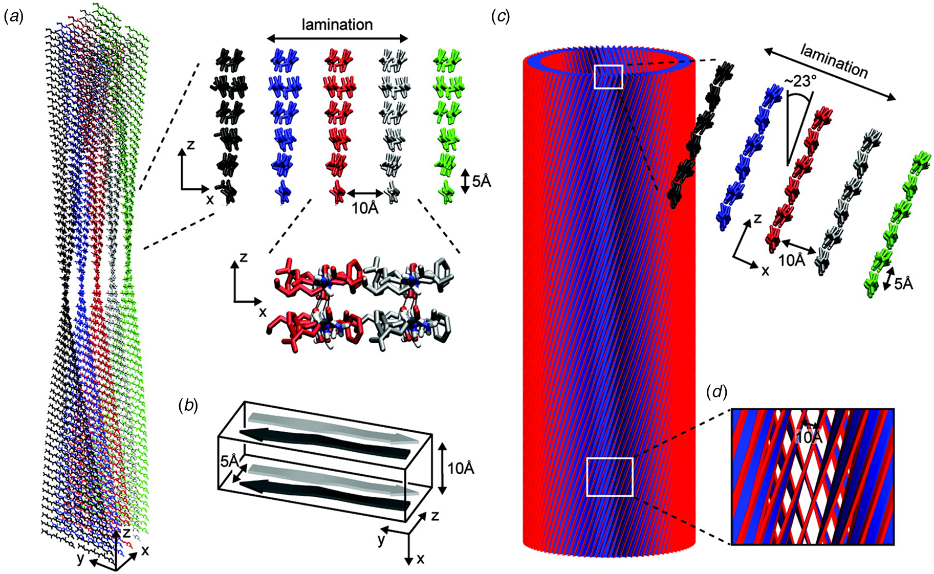
A combination of SAXS/SANS measurements, powder X-ray and electron diffraction, and ssNMR was employed to provide insight into the structural differences between the two morphological forms (Mehta et al., Reference Mehta, Lu, Childers, Liang, Dublin, Dong, Snyder, Pingali, Thiyagarajan and Lynn2008). The protofilament structure at neutral pH was based on a stack of five cross-β fibrils (Fig. 8a and b), in which adjacent Aβ16-22 peptides were arranged in exact registry in an antiparallel β-sheet. In contrast, the Aβ16-22 nanotubes are arranged in an antiparallel β-sheet in which adjacent peptides adopt an alternating single-residue offset (Fig. 8c and d). Each nanotube consists of an indeterminate number of cross-β protofilaments based on a bilayer structure. Individual protofilaments are oriented at an angle of ~23° with respect to the helical axis of the tube. Conventional TEM and AFM measurements, performed under acidic conditions, indicated that bilayer ribbons formed in solution within 30 h. The ribbons eventually closed to form the nanotube through fusion of the edges. The evolution of morphology from twisted ribbons to helical ribbons to tubes has been observed often for self-assembly processes involving chiral monomers, including amyloidogenic peptides and proteins (Selinger et al., Reference Selinger, Selinger, Malanoski and Schnur2004; Ziserman et al., Reference Ziserman, Lee, Raghavan, Mor and Danino2011; Adamcik and Mezzenga, Reference Adamcik and Mezzenga2018).
Morphological variants of Aβ16-22. (a) Atomic model of the laminated filament of Aβ16-22 observed at neutral pH. (b) Proposed unit cell describing the packing of peptides in the laminated filament of Aβ16-22. (c) Atomic model of the bilayer nanotube of Aβ16-22 observed at acidic pH. (d) Expanded representation of the tilted packing of β-strands within a bilayer nanotube of Aβ16-22. Reprinted with permission from Mehta et al. (Reference Mehta, Lu, Childers, Liang, Dublin, Dong, Snyder, Pingali, Thiyagarajan and Lynn2008), Journal of the American Chemical Society, 130(30), 9829–9835. Copyright 2021 American Chemical Society.
Like Aβ, α-synuclein (α-syn) is a natural protein that self-assembles into cross-β fibrils. The presence of these fibrils has been associated with degeneration of dopaminergic neurons that is a symptom of Parkinson's disease (Spillantini et al., Reference Spillantini, Schmidt, Lee, Trojanowski, Jakes and Goedert1997). Morris et al. demonstrated that an eight-residue truncation product derived from α-syn, α-Sβ1, NH2-37VLYVGSK44T-COOH, was able to form a helical ribbon structure (Fig. 9a) (Morris et al., Reference Morris, Zibaee, Chen, Goedert, Sikorski and Serpell2013). The initial assemblies evolved over time; subsequently forming a closed nanotube through sealing of the edges of the tape (Fig. 9b). Structural models were constructed for the ribbon and tube using medium-resolution data acquired from a combination of conventional TEM, FTIR, and X-ray fiber diffraction analyses (Fig. 9c–e). The peptide sequence displays contour-length amphiphilicity with a hydrophobic N-terminal segment and hydrophilic C-terminal segment. Self-assembly resulted in the formation of a nanotube based on an amphiphilic bilayer in which the hydrophobic segments were sequestered in the interior and the hydrophilic segments decorated the convex and concave surfaces. Each leaflet within the bilayer consisted of peptides packed in parallel β-sheet in which the peptides were oriented in an antiparallel arrangement across the bilayer interface. The α-Sβ1 tubes were ~2400 Å in diameter, which was significantly wider than most peptide-based nanotubes resulting from self-assembly of either biologically derived or synthetic β-sheet peptides.
Proposed mechanism of assembly and structural model of nanotubes derived from self-assembly of α-Sβ1 peptides. (a) Model of the initially formed helical ribbon with associated TEM image. (b) Model of the mature tubes with associated TEM image. (c) Cross-sectional depiction of the mature tube indicating the packing arrangement of peptides in the amphiphilic monolayer. (d) Sequence and stick model of the α-Sβ1 peptide. Residues are colored to indicate amphiphilic character based on water-octanol transfer free energies. (e) The orientation of the α-Sβ1 strands are shown in the context of the tape then leading to the nanotubes. The single peptides are represented as lines with hydrophobicity and hydrophilicity shown as orange and cyan, respectively. Reprinted with permission from Morris et al. (Reference Morris, Zibaee, Chen, Goedert, Sikorski and Serpell2013), Angewandte Chemie International Edition, 52(8), 2279–2283.
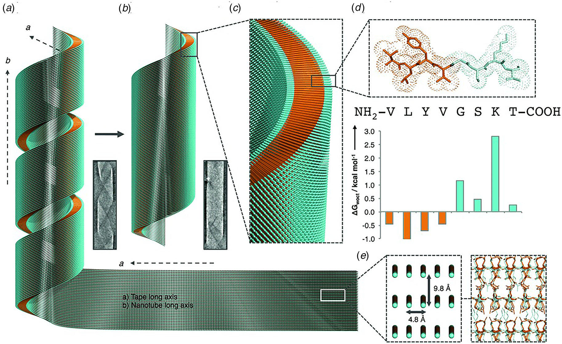
The self-association behavior of the α-Sβ1 peptide was similar to that of Aβ16-22 in that wide-diameter, thin-walled nanotubes resulted from in vitro assembly under ambient conditions. While the sequences were different, both peptides displayed contour-length amphiphilicity, i.e. the sequence could be formally parsed into distinct polar and non-polar segments along the peptide backbone. This sequence pattern more closely resembled conventional amphiphiles such as phospholipids or amphiphilic block copolymers, rather than the facially amphiphilic cross-β fibrils described in the preceding section. Consequently, the layered packing of peptides within the respective nanotubes is reminiscent of the leaflet structure of lipids, in which the hydrophobic portions of the peptide sequence are buried in the core of a monolayer or bilayer with the polar groups decorating the solvent-contacting surfaces (Figs 8 and 9).
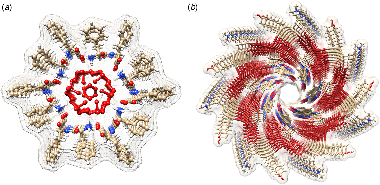
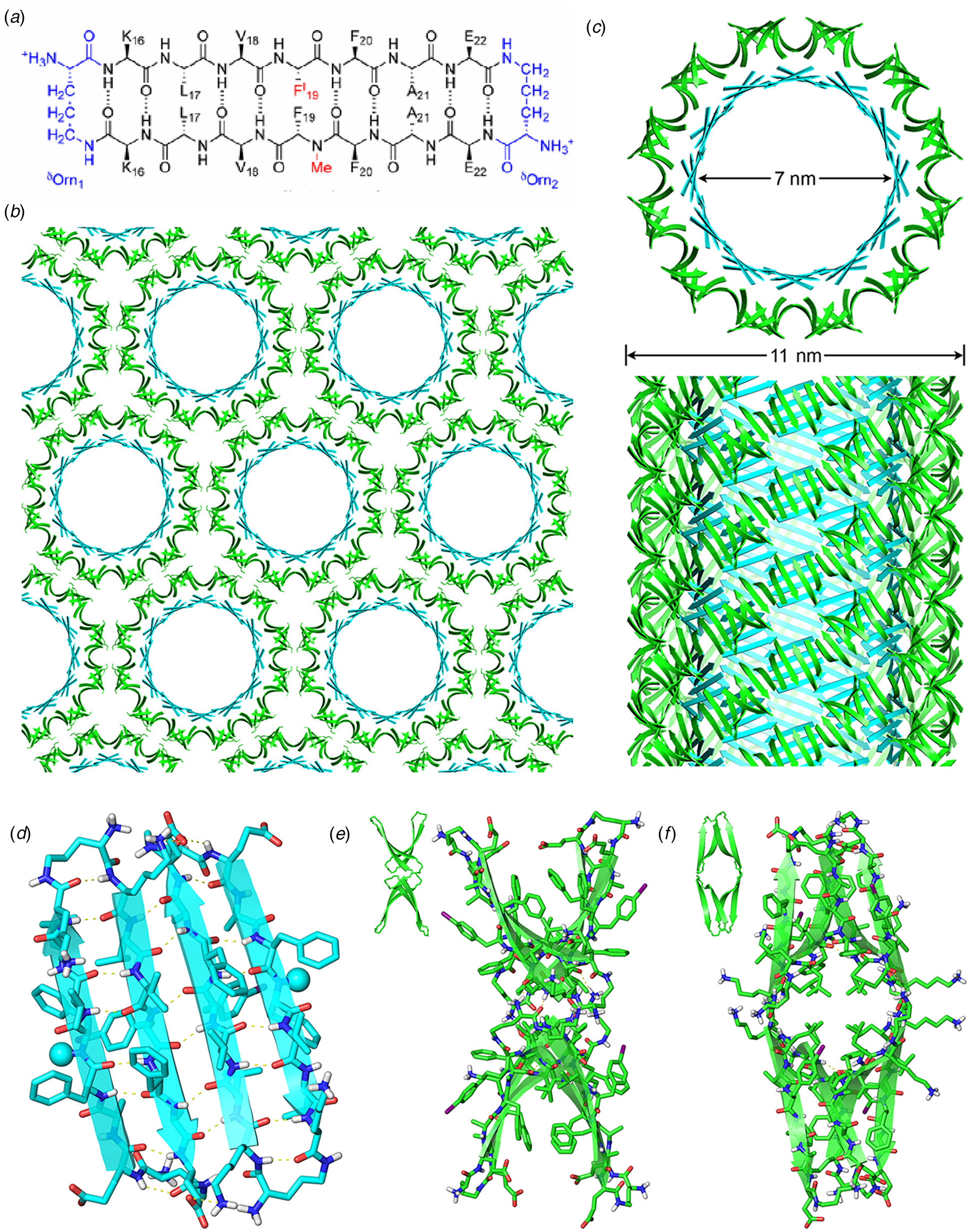
Amyloidogenic peptide segments can be incorporated into more complex sequence architectures to promote unique modes of nanotube self-assembly. Nowick and coworkers reported the crystal structure of a macrocyclic β-sheet peptide, 1, derived from the Aβ16-22 sequence (PDB: 5VF1) (Chen et al., Reference Chen, Corro, Le and Nowick2017). The KLVFFAE sequence was combined with EAFFVLK, its retro-sequence, in a cyclic arrangement in which the two peptide segments were covalently connected with δ-ornithine amide-bond linkages (Fig. 10a). For this peptide sequence, macrocyclization limited the accessible conformational space that the peptide could adopt, which presumably restricted the range of supramolecular structures that could result from self-assembly. Crystallographic analysis revealed the presence of nanotubes that formed a porous, hexagonally close-packed lattice under the P6122 space group symmetry of the crystal structure (Fig. 10b). Individual nanotubes within the crystal were double-walled and the asymmetric unit consisted of six macrocyclic peptides, in which the inner (concave) and outer (convex) walls of the nanotube were composed of helical arrays of structurally distinct dimers and tetramers, respectively. The dimers at the concave surface self-associated through the formation of hydrogen bonds between the backbone of each monomer and were further stabilized through complementary charge interactions between β-strands (Fig. 10c and d). The tetramers associated via a combination of hydrogen bonds and hydrophobic interactions in a β-barrel-like structure (Fig. 10c and e). Each tetramer was associated with four other tetramers by hydrogen bonds. The hexagonal close-packed arrangement of tubes, viewed along the crystallographic c-axis, was consistent with the formation of assemblies in solution and subsequent lateral association in the crystal structure. A similar mechanism has been proposed for the formation of nematic liquid crystalline phases in the self-assembly of nanotubes from the A6K peptide (vide infra) (Bucak et al., Reference Bucak, Cenker, Nasir, Olsson and Zackrisson2009). It is interesting to note that despite the conformational constraints that macrocyclization imposed on the peptide sequence, the resultant structure, especially the outer wall of the nanotube, would have been difficult to predict based on our current knowledge of peptide and protein quaternary structure.
(a) Sequence of macrocyclic β-sheet 1. (b) Macrocyclic β-sheet 1 nanotubes pack into a honeycomb-like crystal lattice. (c) Top and side views of nanotube formed by macrocyclic β-sheet 1. (d) Structure of dimeric subunit at the inner wall of the nanotube. (e, f) Different views of the tetrameric subunit at the outer wall of the nanotube. Reprinted with permission from Chen et al. (Reference Chen, Corro, Le and Nowick2017), Journal of the American Chemical Society, 139(24), 8102–8105. Copyright 2021 American Chemical Society.
Contour-length amphiphilicity has been employed as an explicit design principle to engineer the sequences of synthetic self-assembling peptides. When these designs incorporate amino acids that display a preference for the formation of β-strand conformation, self-assembly of the corresponding sequences often resulted in supramolecular architectures based on β-sheet formation. Zhang and co-workers were the first researchers to employ this concept to design a class of synthetic surfactant-like peptides (SLPs) based on sequences that displayed contour-length amphiphilicity (Vauthey et al., Reference Vauthey, Santoso, Gong, Watson and Zhang2002). In contrast to the adventitious amphiphilicity of the Aβ16-22-derived and α-Sβ1 peptides, Zhang's SLP designs were directly analogous to small-molecule amphiphiles. The peptide sequences consisted of a polar head group of one or two charged amino acid residues, and a non-polar tail composed of a short sequence of hydrophobic amino acids. The properties of these peptide surfactants have been studied extensively over the past two decades (Hamley, Reference Hamley2011). Thus far, however, the structures of the resultant assemblies have not been described at NAR.
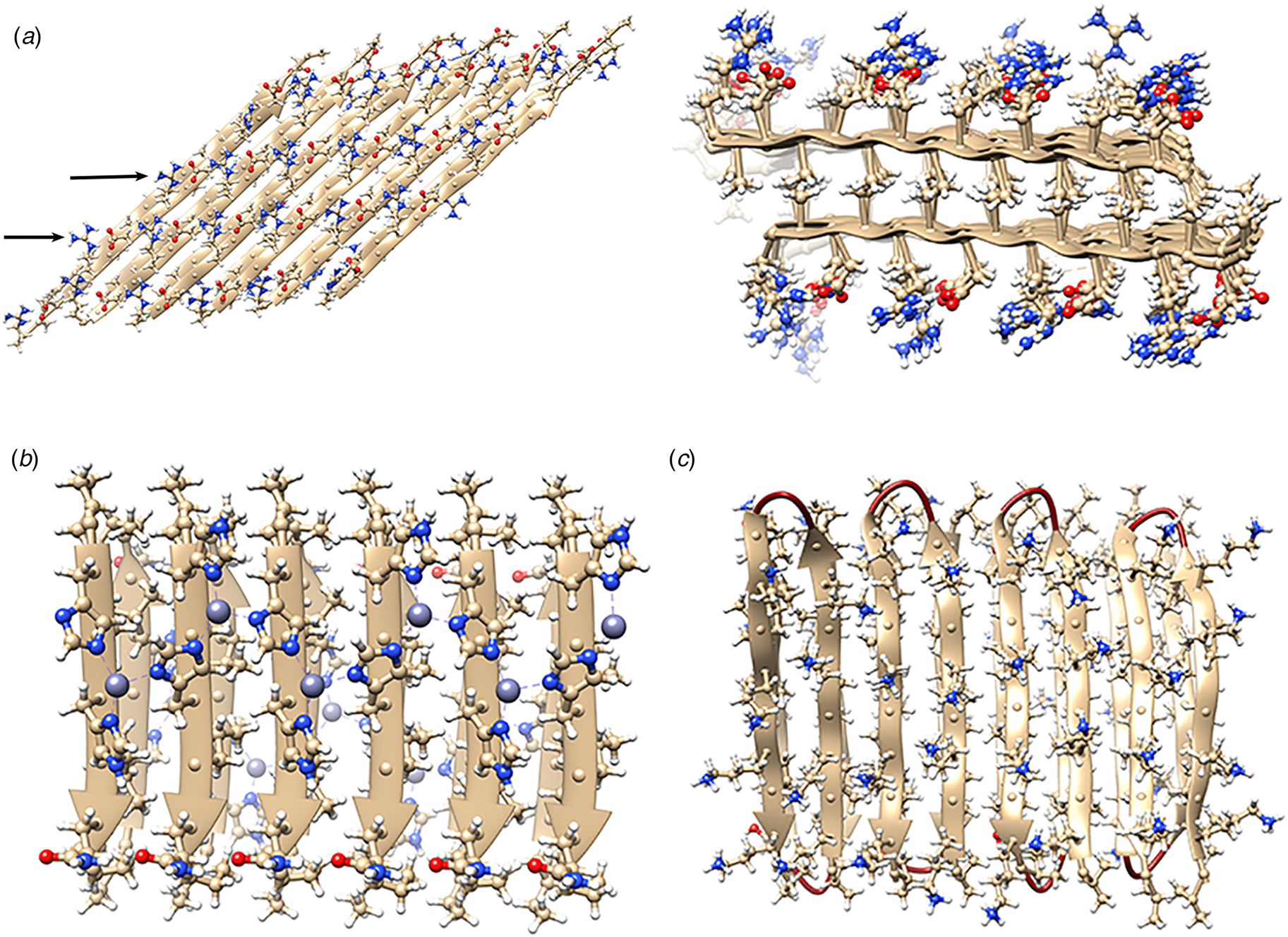
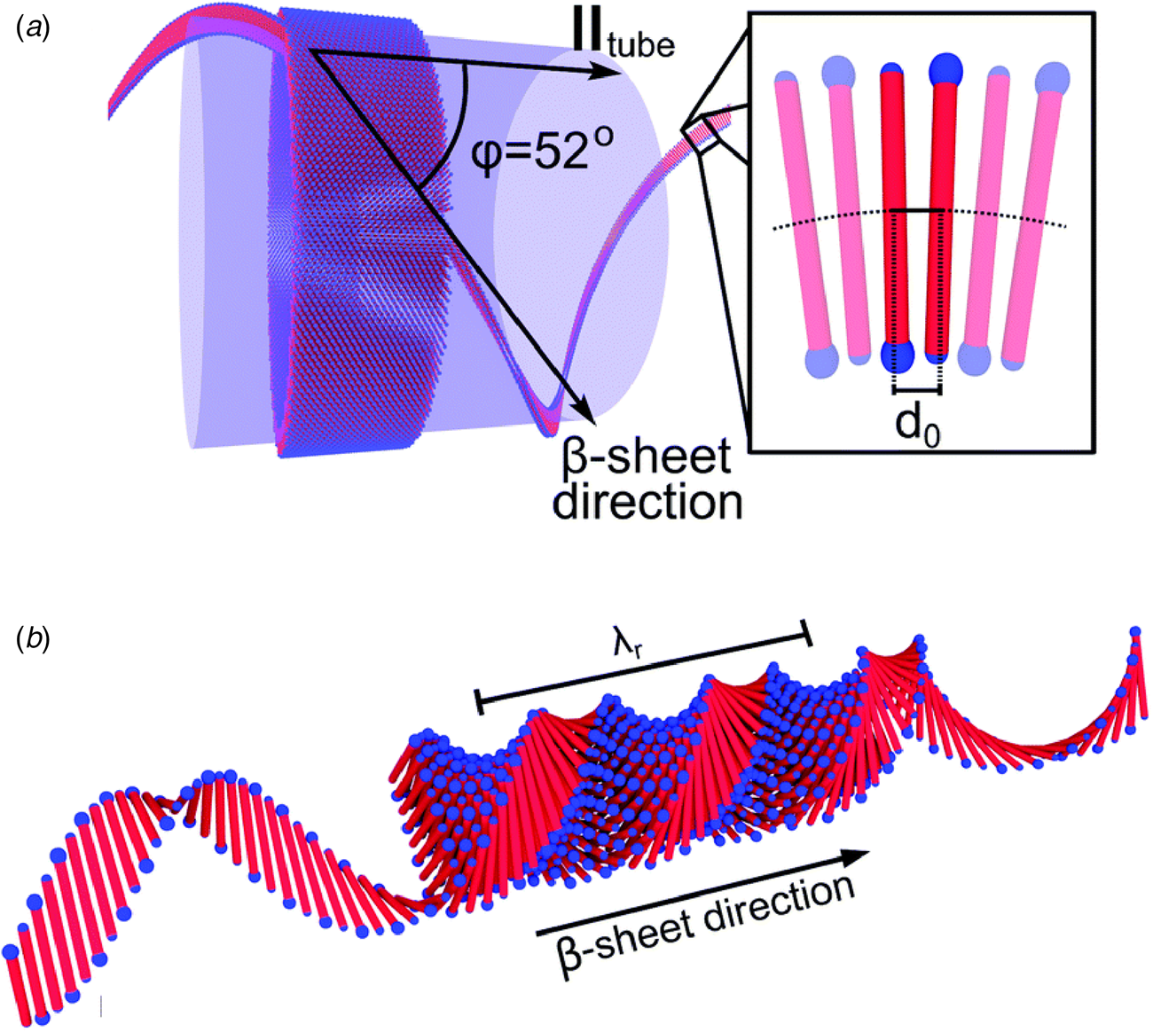
The surfactant peptide, NH2-AAAAAAK-COOH (A6K), has been the most thoroughly investigated member of this class (Bucak et al., Reference Bucak, Cenker, Nasir, Olsson and Zackrisson2009; Castelletto et al., Reference Castelletto, Nutt, Hamley, Bucak, Cenker and Olsson2010; Cenker et al., Reference Cenker, Bomans, Friedrich, Dedeoğlu, Aviyente, Olsson, Sommerdijk and Bucak2012; Middleton et al., Reference Middleton, Madine, Castelletto and Hamley2013). Above a critical volume fraction, A6K formed a nematic meso-phase composed of an apparently homogeneous population of nanotubes with an approximate mean diameter of 550 Å and an estimated shell thickness of 33 Å. SAXS, cryo-EM, ssNMR, and X-ray diffraction of flow-aligned nanotube solutions contributed structural insights that have led to a proposed structural model for the tubes in which protofilaments derived from antiparallel β-sheet architectures were arranged in an amphiphilic monolayer. In the proposed model, structurally adjacent A6K peptides within the cross-β protofilaments were oriented in register (Fig. 11a). Tube formation was proposed to result from lamination of the protofilaments. The H-bonded network of the protofilaments was determined to be oriented at a pitch angle of ~52° with respect to the central axis of the nanotube. In contrast to A6K, the longer-peptide variants, A8K and A10K, form twisted ribbon architectures despite remarkably similar local packing interactions within the unit cells of the respective peptide systems (Rüter et al., Reference Rüter, Kuczera, Stenhammar, Zinn, Narayanan and Olsson2020) (Fig. 11b).
(a) Structural model of a nanotube derived from self-assembly of peptide A6K. A single protofilament within the nanotube inclines at an angle of 52° with respect to the long axis of the assembly. Inset indicates the proposed antiparallel packing arrangement of peptides within a cross-β protofilament. (b) Structural model of a laminated ribbon derived from self-assembly of peptide A8K or A10K. The trajectory of single cross-β protofilament within the ribbon is highlighted. The quantity λ r corresponds to the helical pitch of the ribbon. In both representations, the imposed helical hand was based on an arbitrary decision. Reproduced from Rüter et al. (Reference Rüter, Kuczera, Stenhammar, Zinn, Narayanan and Olsson2020), Physical Chemistry Chemical Physics, 22(33), 18320–18327, with permission from the Royal Society of Chemistry.
Peptide surfactants based on bolaamphiphile architectures have also been demonstrated to self-assemble into cross-β nanotubes. Bolaamphiphiles display an alternate mode of contour-length amphiphilicity, in which the sequence was composed of a hydrophobic core with flanking terminal polar residues, e.g. RFL4FR, EFL4FE, or KI4K (Zhao et al., Reference Zhao, Wang, Deng, Zhou, Wang, Wang, Xu and Lu2013; Da Silva et al., Reference Da Silva, Alves, Castelletto, Reza, Ruokolainen, Hussain and Hamley2015a, Reference Da Silva, Walter, Reza, Castelletto, Ruokolainen, Connon, Alves and Hamley2015b; Hamley et al., Reference Hamley, Burholt, Hutchinson, Castelletto, Da Silva, Alves, Gutfreund, Porcar, Dattani, Hermida-Merino, Newby, Reza, Ruokolainen and Stasiak2017). For example, the bolaamphiphilic peptide Ac-KI4K-NH2 assembled into wide-diameter, thin-walled nanotubes, despite the potential for electrostatic repulsion between the terminal lysine residues. In contrast, the amphiphilic peptide Ac-I4K2-NH2, in which charges are localized at the C-terminus, formed thin, twisted filaments, which suggested that the polar sequence pattern had an influence on supramolecular structure despite the fact that both peptides adopted a β-sheet conformation in the assembled state. Zhao et al. demonstrated that, in aqueous solution, hydrophobic interaction between the isoleucines in Ac-KI4K-NH2 drove the formation of nanotubes (Zhao et al., Reference Zhao, Deng, Wang, Xu and Lu2015). In contrast, upon addition of acetonitrile (ACN), the peptides assembled into twisted tapes (20% ACN) or thin fibrils (80% ACN). According to CD data, the β-sheet structure was not disrupted in the presence of ACN. However, the addition of ACN reduced the polarity and dielectric constant of the aqueous solvent, which weakened the hydrophobic interaction between the side chains of the isoleucine residues. The weakening of the hydrophobic interactions was proposed to result in a lower degree of sheet lamination, which was hypothesized to underlie the morphological transition from tubes to ribbons to fibrils.
The short sequences of these bolaamphiphilic peptides represent a flexible platform to examine the effect of mutagenesis on the resultant supramolecular structure of the corresponding nanotubes. Interestingly, substitution of residues within the hydrophobic core was observed to influence the diameter of the corresponding nanotubes (Zhao et al., Reference Zhao, Yang, Wang, Wang, Li, Hu, King, Rogers, Lu and Xu2018). The parent sequence, Ac-KI4K-NH2, was modified through introduction of hydrophobic amino acids having different steric properties. In the series Ac-KInV4-nK-NH2 (n = 1–4), SANS, TEM, and cryo-EM measurements indicated that the diameter of the corresponding tubes decreased as the number of isoleucine residues (n) decreased, i.e. with increasing numbers of valine residues within the sequence (Fig. 12). A similar effect was observed for substitutions of the C-terminal isoleucine in the parent sequence with either leucine or norleucine. In the latter situation, the peptides differed from isoleucine in the side-chain structure, which resulted in constriction of the diameter of the resultant nanotubes. Although the structures were not analyzed at NAR, these results indicated that the supramolecular structure of the nanotubes could be rationally varied through sequence modifications. More detailed structural analyses should provide insight into the interplay of factors that control higher-order assembly within this peptide family.
Schematic illustration of the self-assembly of peptide nanotubes derived from site-directed mutagenesis of peptide Ac-KI4K-NH2. (a) Proposed model for self-assembly of the parent peptide Ac-KI4K-NH2. (b) Thin tubes are formed by changing side-chain branching and hydrophobicity, which influences the degree of lateral stacking of β-sheets. (c) A single mutation of isoleucine to valine in Ac-KI3VK-NH2 leads to an intermediate degree of sheet lamination and modest decrease in nanotube diameter. The assignment of helical hand was based on AFM measurements. Reprinted with permission from Zhao et al. (Reference Zhao, Yang, Wang, Wang, Li, Hu, King, Rogers, Lu and Xu2018), Small, 14(12), 1703216.
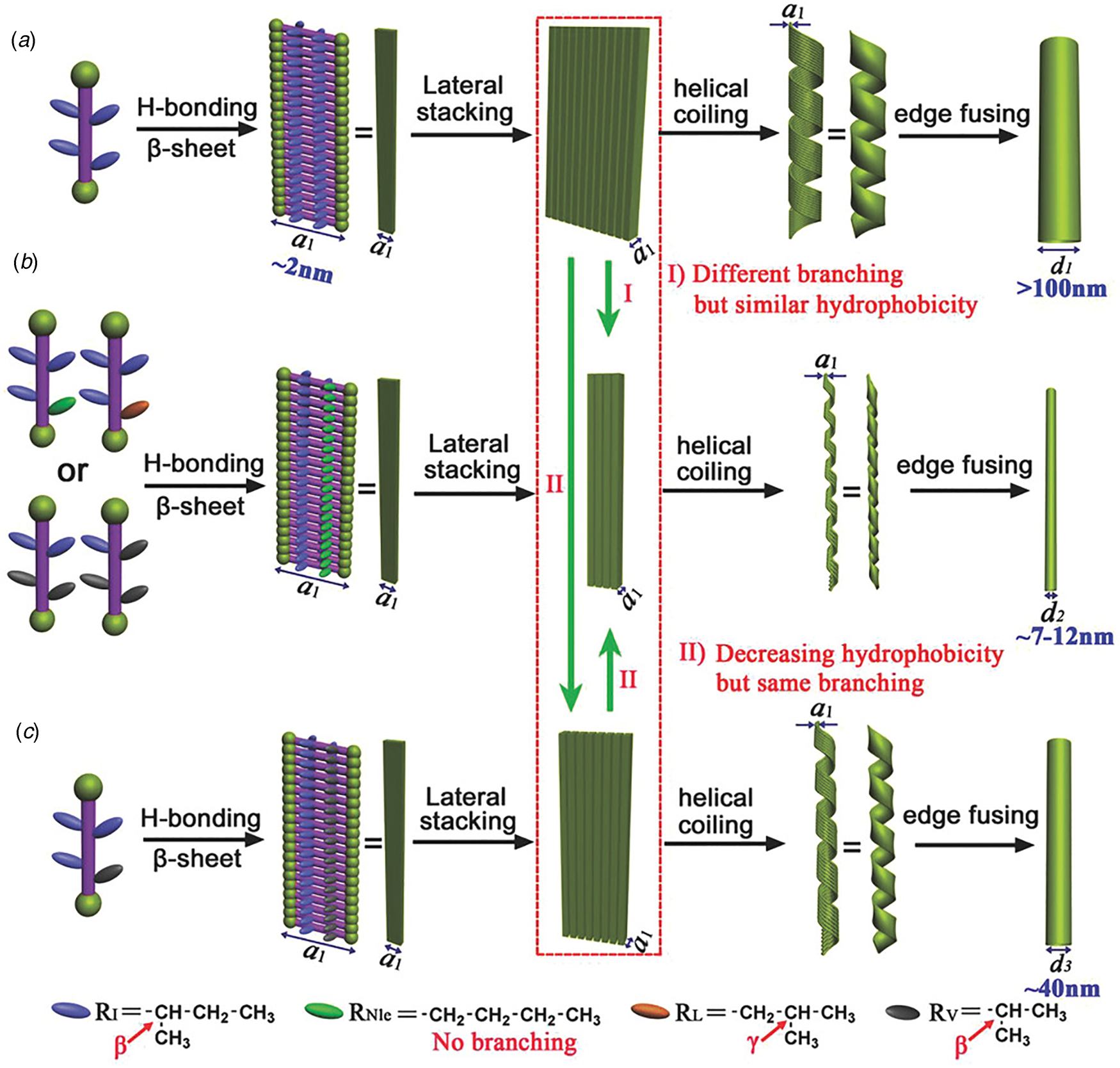
Nanotube formation was also observed in a series of amphiphilic block co-polypeptides Ac-[ALV]x-b-[KGE]y-NH2 (x + y = 7) (Van Rijt et al., Reference Van Rijt, Ciaffoni, Ianiro, Moradi, Boyle, Kros, Friedrich, Sommerdijk and Patterson2019). TEM analysis indicated that peptide Ac-[ALV]3-b-[KGE]4-NH2 self-assembled to form high aspect-ratio nanotubes of ~90 Å in diameter that were stable over a wide pH range (pH = 2–12) and at temperatures up to 80 °C. Cryo-EM and SAXS analysis confirmed the nanotube morphology, while FTIR spectroscopy supported the formation of β-sheet within the assembly. The proposed structure was based on a monolayer nanotube in which adjacent peptides were aligned in an antiparallel orientation such that the hydrophilic blocks decorated the inner and outer surfaces of the tube. A sequence with a smaller hydrophobic block, Ac-[ALV]2-b-[KGE]5-NH2, remained as an unassociated monomer under the same conditions. Longer hydrophobic blocks resulted in kinetically trapped mixtures of nanotubes and cylindrical micelles or in macro-phase separation. In analogy to synthetic amphiphilic block copolymers, these results suggested that the hydrophilic–hydrophobic balance could be employed as a parameter to control self-assembly and supramolecular structure as has been observed for synthetic block copolymers (Jiao et al., Reference Jiao, Yang, Wu, Liu and Zhang2020). In the cases of peptide-based and peptido-mimetic materials based on sequence-specific oligomers, the hydrophilic–hydrophobic balance should be easily amenable to synthetic control.
Lanreotide acetate, an 8-residue, disulfide-linked, cyclic peptide hormone, has also been demonstrated to form nanotubes of homogeneous diameter (~280 Å) above a critical aggregation concentration in aqueous solution (Valéry et al., Reference Valéry, Paternostre, Robert, Gulik-Krzywicki, Narayanan, Dedieu, Keller, Torres, Cherif-Cheikh, Calvo and Artzner2003, Reference Valéry, Artzner, Robert, Gulick, Keller, Grabielle-Madelmont, Torres, Cherif-Cheikh and Paternostre2004; Pouget et al., Reference Pouget, Fay, Dujardin, Jamin, Berthault, Perrin, Pandit, Rose, Valéry, Thomas, Paternostre and Artzner2010). Nanotube assembly coincided with formation of a hexagonal columnar meso-phase. The structure of the lanreotide nanotubes was initially investigated using a combination of EM, FTIR spectroscopy, and SAXS/WAXS diffraction analysis. Based on this evidence, the octapeptide was proposed to fold into a conformationally constrained β-hairpin. Monomers were suggested to initially associate to form face-to-face dimers (Fig. 13) due to attraction between hydrophobic residues and repulsion between positively charged residues. The dimers were hypothesized to subsequently assemble into helical ribbons through aromatic interactions and hydrogen bonds (Valéry et al., Reference Valéry, Paternostre, Robert, Gulik-Krzywicki, Narayanan, Dedieu, Keller, Torres, Cherif-Cheikh, Calvo and Artzner2003, Reference Valéry, Artzner, Robert, Gulick, Keller, Grabielle-Madelmont, Torres, Cherif-Cheikh and Paternostre2004; Pouget et al., Reference Pouget, Fay, Dujardin, Jamin, Berthault, Perrin, Pandit, Rose, Valéry, Thomas, Paternostre and Artzner2010). For the parent lanreotide sequence, the initial structural model for the lanreotide nanotubes was based on the self-association of 26 bilayer protofilaments, in which the peptide backbones are arranged circumferentially around the periphery of the nanotube (Chervy et al., Reference Chervy, Petcut, Rault, Meriadec, Bizien, François, Richard, Chassaing, Benamar, Artzner and Paternostre2019).
Initial model for the self-assembled nanotubes of the lanreotide peptide. Freeze-fracture micrographs of longitudinally (a, b) and transversely (c) fractured nanotubes indicated the formation of uniform-diameter assemblies. (d) Proposed arrangement of lanreotide monomers in the internal and external leaflets of the bilayer nanotube. (e) Initial structural model of the bilayer nanotube with an expansion of the internal and external leaflets corresponding to 2 × 3 asymmetric units. (f) Cross-sectional model of the bilayer nanotube indicating the proposed side-chain packing arrangement between monomers at the leaflet interface. Reproduced from Chervy et al. (Reference Chervy, Petcut, Rault, Meriadec, Bizien, François, Richard, Chassaing, Benamar, Artzner and Paternostre2019), Langmuir, 35(32), 10648–10657, with permission from the American Chemical Society.
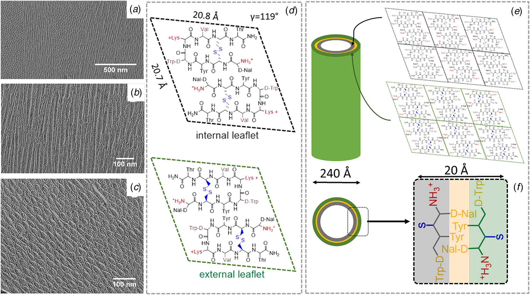
The structure of the lanreotide tubes has been recently determined using cryo-EM analysis (Pieri et al., Reference Pieri, Wang, Arteni, Vos, Winter, Le Du, Artzner, Gobeaux, Legrand, Boulard, Bressanelli, Egelman and Paternostre2022). Helical reconstruction from the projection images afforded a 3D density map at 2.5 Å resolution (PDB: 7Q5A), which represented the highest resolution achieved thus far for a synthetic peptide nanotube. At this level of resolution, the helical hand of the symmetry could be assigned directly based on a structural comparison of atomic models constructed through direct fitting into the two different enantiomorphs that resulted from mirroring the density map. The helical symmetry of the lanreotide model was best described in terms of a right-handed 1-start helix with a rise of 1.04 Å and a rotation of 26.2° (Fig. 14). Surprisingly, the asymmetric unit was based on eight peptides arranged in a monolayer shell in which the peptide backbones extend radially outward from the central axis of the assembly. The hydrogen-bonding direction, corresponding to the cross-β structural interaction, occurs between peptides in every 27th asymmetric unit. The left-handed twist (−12.1°) of this 27-start helix is consistent with the left-handed twist observed for β-sheet in globular proteins and amyloid fibers (Chothia, Reference Chothia1973; Chamberlain et al., Reference Chamberlain, Macphee, Zurdo, Morozova-Roche, Hill, Dobson and Davis2000). The lanreotide nanotube structure differed significantly from the original model and highlighted the necessity of high-resolution structural analysis to fully understand peptide packing within helical filaments. In addition, unlike many synthetic peptide filaments, the population of lanreotide nanotubes was uniform in diameter with negligible polymorphism. The high degree of structural uniformity within the assembly may have derived from the conformational constraints of the cyclic peptide monomer, which could have restricted interfacial interactions to specific geometries within the assembly through pre-organization.
Cryo-EM structure of lanreotide nanotubes. (a) Representative cryo-EM image of peptide nanotubes derived from self-assembly of lanreotide acetate. (b) Representative 2D class average derived from cryo-EM analysis of lanreotide nanotubes. (c) Density maps for the two main conformations, capped versus away, of the lanreotide peptide within the nanotubes. (d) Density map for the lanreotide nanotube in which the eight peptides in an asymmetric unit are highlighted within the assembly. An expansion of the asymmetric unit is depicted on the right in which the capped (orange) and away (cyan) conformations are indicated.
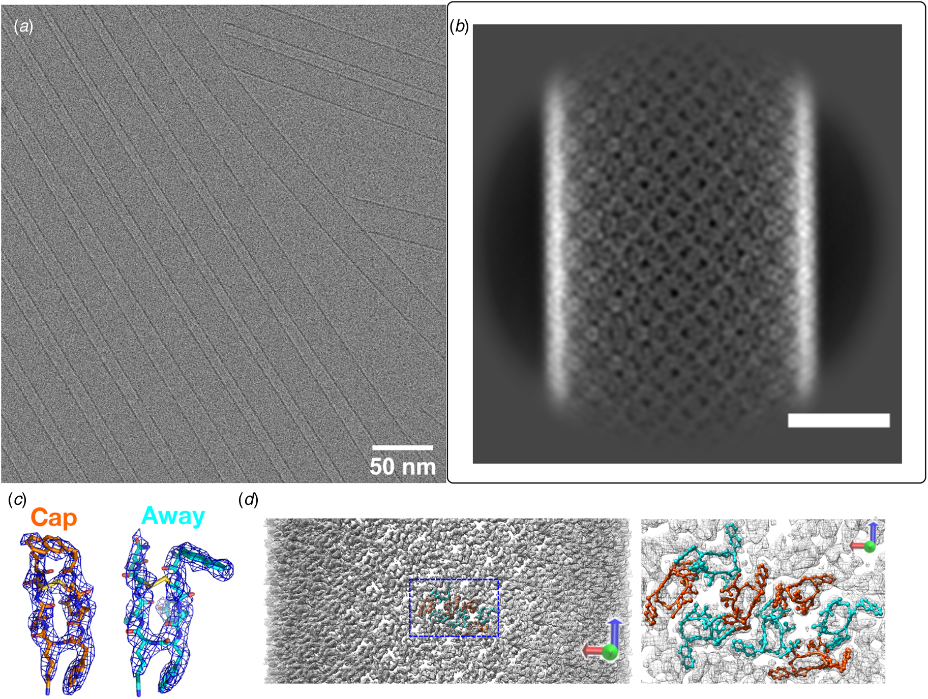
The small size and constrained conformation of lanreotide acetate made it an attractive substrate to investigate the effect of sequence modifications and counterion effects on nanotube structure. Tarabout et al. demonstrated that substitution of the D-Trp4 residue with other aromatic amino acids led, in most cases, to retention of nanotube formation (Tarabout et al., Reference Tarabout, Roux, Gobeaux, Fay, Pouget, Meriadec, Ligeti, Thomas, IJsselstijn, Besselievre, Buisson, Verbavatz, Petitjean, Valery, Perrin, Rousseau, Artzner, Paternostre and Cintrat2011). However, the diameter of the resultant monodisperse nanotubes depended on the size of the amino acid side chain at position 4 and ranged from 100 to 360 Å. Larger side chains increased the nanotube diameter, while smaller side chains had the opposite effect. The observed results were rationalized in terms of the influence of the molecular size parameter of the residue on the curvature at the concave interface between protofilaments. Counterion identity was also observed to influence diameter, although the effect could not be rationalized solely in terms of counterion size (Gobeaux et al., Reference Gobeaux, Fay, Tarabout, Meriadec, Meneau, Ligeti, Buisson, Cintrat, Nguyen, Perrin, Valery, Artzner and Paternostre2012). The high-resolution structure of the parent lanreotide nanotubes should prompt a re-analysis of these mutagenesis results in terms of the structural influence of the substitutions on the packing of peptides in atomic model (Fig. 14).
Paternostre and coworkers (Valery et al., Reference Valery, Deville-Foillard, Lefebvre, Taberner, Legrand, Meneau, Meriadec, Delvaux, Bizien, Kasotakis, Lopez-Iglesias, Gall, Bressanelli, Le Du, Paternostre and Artzner2015) subsequently reported the structural analysis of assemblies derived from triptorelin, a decapeptide that acts as a gonadotropin-releasing hormone agonist. Like lanreotide, the sequence of triptorelin contains a D-Trp residue, which was proposed to be involved in the formation of a reverse turn. In aqueous solution, triptorelin formed nanotubes in which the diameter depended on the pH of the buffer. At low pH (<6.5), small diameter (~11 Å) tubes were formed, while larger diameter (~50 Å) tubes were formed at higher pH (>7.5). This transition was proposed to involve a switch in the protonation state of a histidine side chain within the peptide sequence, which induced a structural transition within the protomer. X-ray crystallographic analysis was performed on triptorelin at high pH under conditions that resulted in flat lamellar structures rather than wide-diameter nanotubes. The structure (PDB: 4D5M) indicated the absence of β-sheet and the formation of a small globular fold that was stabilized through a hydrogen bonding interaction between the side chains of His(2) and Ser(4). The authors suggested that this interaction was lost at low pH, which resulted in the formation of β-sheet conformation.
Conticello and coworkers reported the cryo-EM structural analysis of assemblies derived from an amphipathic peptide KFE8, Ac-FKFEFKFE-NH2 (Wang et al., Reference Wang, Gnewou, Wang, Osinski, Zuo, Egelman and Conticello2021b). This peptide had been previously reported to self-assemble into left-handed helical ribbons (Marini et al., Reference Marini, Hwang, Lauffenburger, Zhang and Kamm2002; Hwang et al., Reference Hwang, Marini, Kamm and Zhang2003). However, over the course of assembly, ribbons and nanotubes were observed, although the structure of the nanotubes depended on the assembly conditions. Cryo-EM analysis was employed to generate NAR models for two ribbons and three nanotubes (PDB: LQE, 7LQF, 7LQG, 7LQH, and 7LQI). At ambient temperature, the nanotubes were based on a bilayer structure consisting of four β-sandwich protofilaments, while under annealing the peptide assembled into nanotubes comprising five β-sandwich protofilaments (Fig. 15). Although the structures of the nanotubes differed, each protofilament was based on an unprecedented packing arrangement in which an inner layer of parallel β-sheet was packed against an outer layer of antiparallel β-sheet. The dependence of nanotube structure on minor changes under preparative conditions suggested that self-assembly was a kinetically controlled process. The resultant polymorphism could critically impact use of these resultant assemblies in biological applications through alteration of the structural interactions at the cell–biomaterial interface.
Peptide KFE8 self-assembles into helical ribbons and nanotubes. Representative cryo-EM images of KFE8 assembled at ambient temperature (a) or annealed at 90 °C (b). Scale bar = 20 nm. Red, black, and white arrows indicate the presence of bilayer ribbons, thinner tubes, and thicker tubes, respectively. Cross-sectional and transverse views of the atomic models for the ribbons (c, f), thinner tubes (d, g), and thicker tubes (e, h). The helical hand was assigned based on imaging data from AFM measurements. Reference: Wang, F.; Gnewou, O.; Wang, S.; Osinski, T.; Zuo, X.; Egelman, E. H.; Conticello, V. P. Deterministic chaos in the self-assembly of β-sheet nanotubes from an amphipathic oligopeptide. Matter, DOI:10.1016/j.matt.2021.06.037.
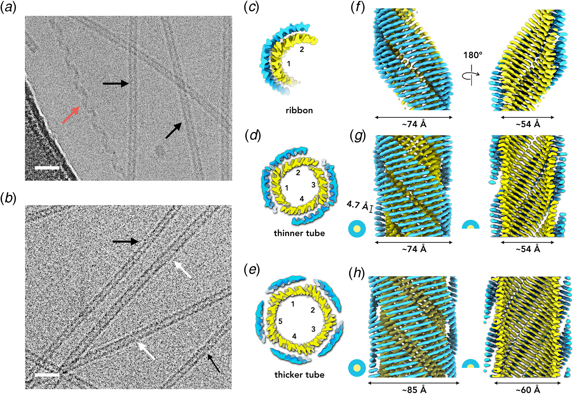
Taken together, these data results provide convincing evidence that helical filaments and nanotubes can result from self-assembly of appropriately designed peptides that adopt a cross-β conformation. Thus far, it has been challenging to reliably and accurately predict the supramolecular structure of such helical filaments from peptide sequence information, which contrasts with recent advances in prediction of tertiary structure (Baek et al., Reference Baek, Dimaio, Anishchenko, Dauparas, Ovchinnikov, Lee, Wang, Cong, Kinch, Schaeffer, Millan, Park, Adams, Glassman, Degiovanni, Pereira, Rodrigues, Van Dijk, Ebrecht, Opperman, Sagmeister, Buhlheller, Pavkov-Keller, Rathinaswamy, Dalwadi, Yip, Burke, Garcia, Grishin, Adams, Read and Baker2021; Jumper and Hassabis, Reference Jumper and Hassabis2022). The structural information within the Protein Data Bank may not be sufficient at present to provide insight that would enable reliable prediction of atomic structure for most assemblies described here. In combination with the frequently observed polymorphism of β-sheet assemblies, the opportunities for reliable de novo design of synthetic β-sheet filaments remain relatively limited at present. However, the explosive growth of high-resolution structural data on amyloids over the past two decades provides evidence that supramolecular structural prediction might at some point in the near future become a tractable problem that would enable de novo design of β-sheet assemblies.
Coiled-coil filaments
Similar to β-sheet assemblies, α-helical filaments can be constructed through molecular design approaches based on polar sequence patterns (Beesley and Woolfson, Reference Beesley and Woolfson2019). However, in contrast to β-strands, the hydrogen bonding interactions in α-helices occur within, rather than between, secondary structure elements. Consequently, α-helical sequences can potentially adopt a stable conformation without self-association, while β-strand formation usually requires self-association between two or more intra- or intermolecular peptide segments. Conversely, β-sheet assemblies derived from short peptides are often more stable than α-helical assemblies, as self-association in the former case is primarily driven through directional hydrogen-bonding between β-strands rather than the weaker hydrophobic interactions that hold together α-helical assemblies (Knowles et al., Reference Knowles, Fitzpatrick, Meehan, Mott, Vendruscolo, Dobson and Welland2007).
The most common mode of self-association between α-helices involves coiling of multiple helices into super-helical architectures known as coiled-coils (Lupas and Bassler, Reference Lupas and Bassler2017; Woolfson, Reference Woolfson2017). Coiled-coil sequences are defined by repeat patterns based on a heptad motif (a-b-c-d-e-f-g), in which the residues at the a- and d-positions of the heptad repeat are usually hydrophobic amino acids. Self-association of helices is mediated through ‘knobs-into-holes’ packing interactions, which were first proposed by Crick in 1953 (Crick, Reference Crick1953). The knobs correspond to the side chains of residues at a- and d-positions, which pack into complementary holes on adjacent helices in the assembly. The pitch of an α-helix corresponds to 3.6 residues, which differs slightly from the 3.5 residues/turn of a coiled-coil. Therefore, the helices in coiled-coil super-coil with a left-handed helical sense to accommodate the ‘knobs-into-holes’ interactions at the hydrophobic interface within the assemblies. In the helical wheel diagram of a coiled-coil, lettered positions are used to describe the architecture of individual α-helices (Fig. 16a). Sighting down the helix with the amino-terminus closest to the viewer, each residue is represented as a vertex of the helical wheel diagram in super-helix space. This diagram represents the relative orientation of residues that form the interacting faces within a given helix with respect to other helices in the axial projection of the coiled-coil.
(a) Helical-wheel diagrams of the SAF-p1, SAF-p2, and SAF-p2a peptides indicating the heptad periodicity. (b) Proposed model for the heteromeric association of SAF-p1 and SAF-p2(a) peptides into a dimeric coiled-coil through sticky-ended self-assembly. (c, d) Transmission electron micrographs of the para-crystalline assembly of SAF-p1 and SAF-p2a co-assembly. (e, f) Simulated model of the packing of coiled-coil peptides within the SAF assembly. Reprinted from Sharp et al. (Reference Sharp, Bruning, Mantell, Sessions, Thomson, Zaccai, Brady, Verkade and Woolfson2012), Proceedings of the National Academy of Sciences of the United States of America, 109(33), 13266–13271.
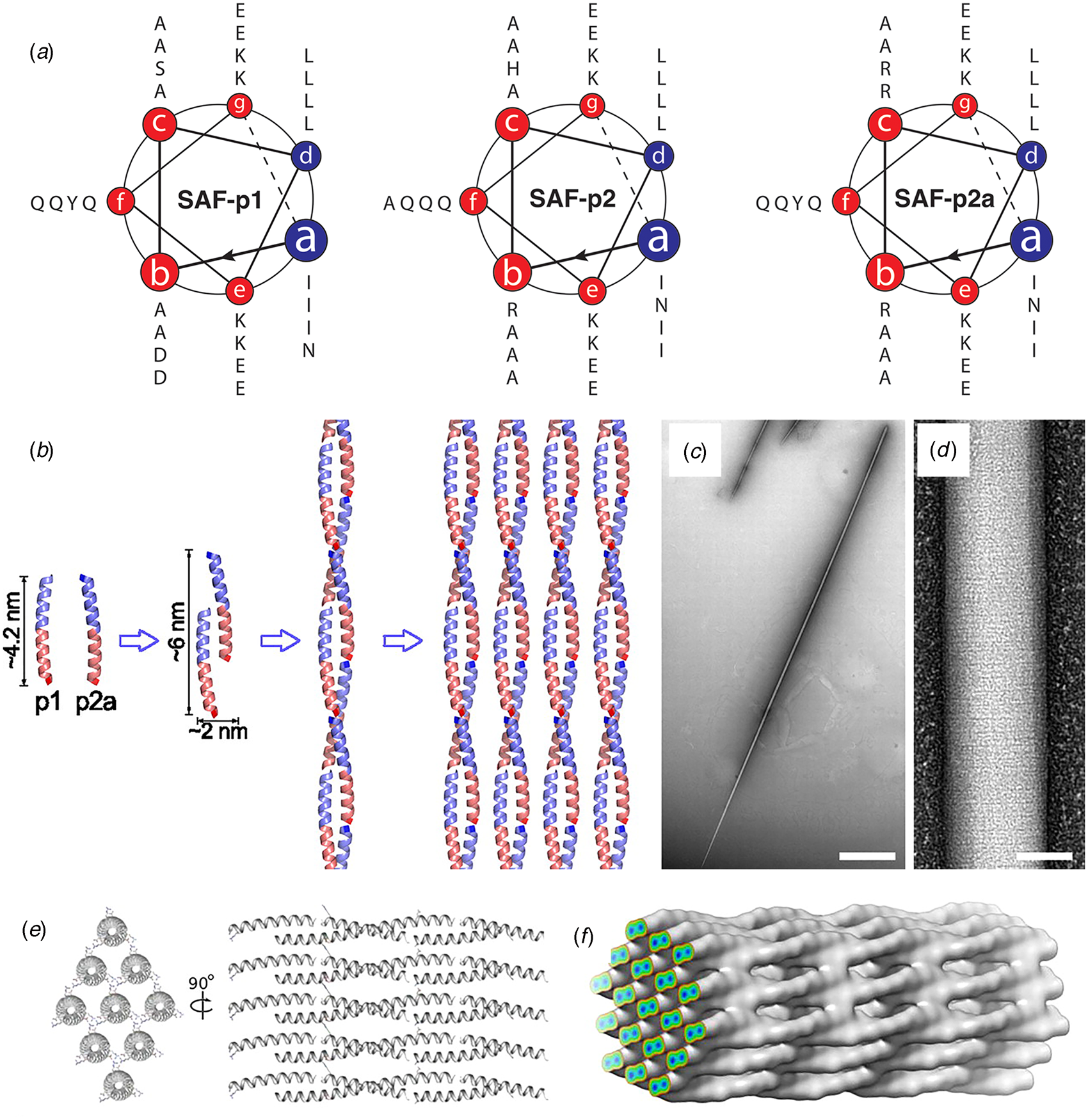
The self-association of coiled-coil sequences usually results in discrete oligomeric states displaying rotational, i.e. cyclic (Cn), symmetry. The degree of oligomerization depends on the identity of the core (a, d) and proximal (e, g) residues of the heptad repeat sequences. Directed mutagenesis and computational design were employed to identify sequences that form Cn-symmetric homomeric oligomers consisting of two to nine α-helices (Zaccai et al., Reference Zaccai, Chi, Thomson, Boyle, Bartlett, Bruning, Linden, Sessions, Booth, Brady and Woolfson2011; Thomson et al., Reference Thomson, Wood, Burton, Bartlett, Sessions, Brady and Woolfson2014; Rhys et al., Reference Rhys, Wood, Lang, Mulholland, Brady, Thomson and Woolfson2018; Dawson et al., Reference Dawson, Martin, Rhys, Shelley, Brady and Woolfson2021). In contrast to native coiled-coil filaments, e.g. intermediate filaments, tropomyosin, etc., designed coiled-coils usually form blunt-ended assemblies due to the short length of synthetic peptides, the in-register alignment of helices within the assembly, and the absence of discrete terminal interaction domains.
A convenient strategy to promote the formation of helical filaments from simple helical bundles involves alteration of the helix–helix registry within the assembly to promote staggered self-association between the α-helices (Pandya et al., Reference Pandya, Spooner, Sunde, Thorpe, Rodger and Woolfson2000; Potekhin et al., Reference Potekhin, Melnik, Popov, Lanina, Vazina, Rigler, Verdini, Corradin and Kajava2001; Zimenkov et al., Reference Zimenkov, Conticello, Guo and Thiyagarajan2004). Strand registry can be specified through the pattern of electrostatic interactions between helices, which usually occur between the residues at e- and g-positions on structurally adjacent helices. In addition, buried polar interactions can be introduced at either the a- or d-positions within the sequences of the helical protomers to control helix–helix alignment within the assembly (Oakley and Kim, Reference Oakley and Kim1998; Akey et al., Reference Akey, Malashkevich and Kim2001).
Woolfson and co-workers employed this approach to fabricate helical assemblies based on a heterodimeric coiled-coil motif (Pandya et al., Reference Pandya, Spooner, Sunde, Thorpe, Rodger and Woolfson2000; Smith et al., Reference Smith, Banwell, Edwards, Pandya and Woolfson2006). A pair of peptides, SAF-p1 and SAF-p2, was designed such that selective heteromeric association would result in a two-heptad offset between the pair of four-heptad peptides. This staggered orientation was enforced through a combination of complementary electrostatic interactions and a buried polar interaction (Fig. 16b). The formation of high aspect-ratio helical filaments was observed through sticky-ended association. The width of the filaments suggested that the dimeric coiled-coil protofilaments associated into bundles through weak non-specific lateral interactions. To promote a more specific lateral association, a modified peptide sequence, SAF-p2a, was designed to introduce electrostatic interactions between filaments through incorporation of arginine and aspartic acid at surface-exposed positions in the dimeric coiled-coil. Self-assembly resulted in the formation of highly ordered, para-crystalline filaments (Fig. 16c and d). Cryo-EM analysis of these filaments at intermediate resolution indicated that the dimers packed in a parallel, hexagonal array. The individual protofilaments within the para-crystalline assemblies corresponded to pseudo-infinite heterodimeric coiled-coils, which were arranged in parallel along the long axis of the para-crystalline assembly (Fig. 16e and f) (Papapostolou et al., Reference Papapostolou, Smith, Atkins, Oliver, Ryadnov, Serpell and Woolfson2007; Sharp et al., Reference Sharp, Bruning, Mantell, Sessions, Thomson, Zaccai, Brady, Verkade and Woolfson2012).
A similar approach has been employed for the design of coiled-coil filaments based on homomeric self-association of peptides derived from coiled-coil dimer and trimer sequences (Zimenkov et al., Reference Zimenkov, Conticello, Guo and Thiyagarajan2004, Reference Zimenkov, Dublin, Ni, Tu, Breedveld, Apkarian and Conticello2006; Gribbon et al., Reference Gribbon, Channon, Zhang, Banwell, Bromley, Chaudhuri, Oreffo and Woolfson2008). However, reliance on a single-peptide sequence significantly constrained design space due to the necessity to incorporate the intermolecular interactions that specify a staggered orientation into single-peptide sequences. In the case of coiled-coil trimers, metal ion binding motifs could be incorporated into the sequence to direct or reinforce helix alignment to trigger assembly or disassembly in response to the presence of specific metal ions (Dublin and Conticello, Reference Dublin and Conticello2008; Anzini et al., Reference Anzini, Xu, Hughes, Magnotti, Jiang, Hemmingsen, Demeler and Conticello2013).
An alternative strategy for the fabrication of filamentous coiled-coil assemblies involved the stacking of discrete oligomeric bundles. Crystallographic analyses of coiled-coil structures provided evidence that discrete helical bundles could stack to form continuous superhelices along the highest order rotational axis (Ogihara et al., Reference Ogihara, Weiss, Degrado and Eisenberg1997; Zaccai et al., Reference Zaccai, Chi, Thomson, Boyle, Bartlett, Bruning, Linden, Sessions, Booth, Brady and Woolfson2011; Lanci et al., Reference Lanci, Macdermaid, Kang, Acharya, North, Yang, Qiu, Degrado and Saven2012). While these coiled-coil assemblies do not usually persist outside of the crystal, the termini of the peptide sequences could be modified to promote axial interactions that would result in the formation of thermodynamically stable helical filaments. This approach is particularly appealing for larger oligomers since the interfacial surface area buried upon the formation of helical stacks would be sufficient to stabilize the resultant assemblies, especially if coupled with other non-covalent interactions, e.g. electrostatic attraction between oppositely charged termini (Xu et al., Reference Xu, Liu, Mehta, Guerrero-Ferreira, Wright, Dunin-Horkawicz, Morris, Serpell, Zuo, Wall and Conticello2013; Burgess et al., Reference Burgess, Sharp, Thomas, Wood, Thomson, Zaccai, Brady, Serpell and Woolfson2015). An additional advantage of this approach is that larger helical bundles, i.e. oligomerization states greater than a tetramer, encompass a central cavity of sufficient size to encapsulate appropriately shaped small molecules (Thomas et al., Reference Thomas, Dawson, Lang, Burton, Bartlett, Rhys, Mulholland and Woolfson2018).
The latter approach was employed for the design of a helical filament based on a seven-helix bundle structure. Starting with the natural two-stranded coiled-coil GCN4 leucine zipper, Lu and coworkers replaced residues at e and g with alanine, which generated the modified peptide GCN4-pAA (Liu et al., Reference Liu, Zheng, Deng, Cheng, Kallenbach and Lu2006), which assembled into a heptameric coiled-coil. The seven-helix bundle displayed a successive single-residue offset between structurally adjacent α-helices, which resulted in a discrete helically symmetric structure that resembled a lock washer (Fig. 17). The heptameric lock washers remained unassociated in solution and in the corresponding crystal structure of GCN4-pAA (PDB: 2HY6). A positively charged arginine at the C-terminal position served as a gatekeeper residue, which prevented axial stacking through introduction of repulsive interactions between the termini of the seven-helix bundles.
Mechanism of self-assembly of coiled-coil lock washers into helical filaments. (a) Helical wheel diagram of designed coil-coil peptide 7HSAP1. (b) Sequence of the 7HSAP1 peptide indicating the heptad registry. Basic and acidic residues involved in the intra-bundle and inter-bundle (axial stacking) interactions are highlighted in blue and red, respectively. (c) Proposed mechanism of self-assembly of heptameric lock washers of 7HSAP1 into filaments through electrostatic interactions between oppositely charged termini. The seven-helix bundle structure was derived from the crystal structure of GCN4-pAA (PDB: 2HY6). Reproduced with permission from Xu et al. (Reference Xu, Liu, Mehta, Guerrero-Ferreira, Wright, Dunin-Horkawicz, Morris, Serpell, Zuo, Wall and Conticello2013), Journal of the American Chemical Society, 135(41), 15565–15578. Copyright 2021 American Chemical Society.
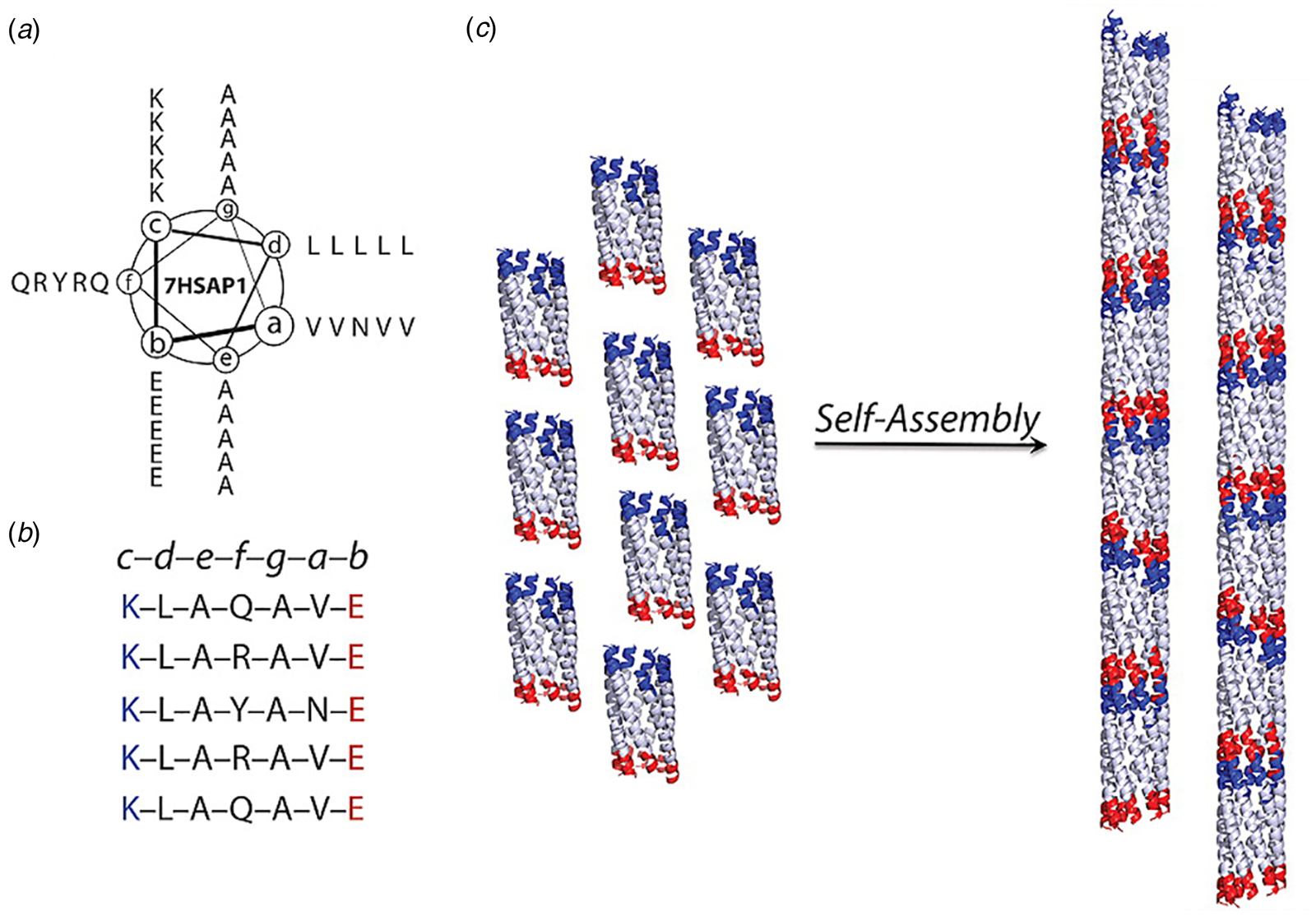
Conticello and coworkers designed a self-assembling peptide nanotube by rationally modifying the sequence of GCN4-pAA (Xu et al., Reference Xu, Liu, Mehta, Guerrero-Ferreira, Wright, Dunin-Horkawicz, Morris, Serpell, Zuo, Wall and Conticello2013). The C-terminal arginine at the d-position was replaced with a leucine, in accord with the canonical sequence preferences for coiled-coils. This substitution restored the continuous hydrophobic interface. In addition, residues at the b- and c-positions of the heptad repeat sequence of GCN4-pAA were replaced with glutamate and lysine, respectively, to introduce electrostatic interactions that reinforced the association between helices in the heptamer. Two arginine residues were added at f-positions to prevent lateral association between helical bundles. The peptide termini were uncapped to promote axial stacking of lock washers through electrostatic interactions (Fig. 17a and b). Spectroscopic analysis of the corresponding peptide, 7HSAP1, confirmed the presence of α-helical assemblies. TEM measurements indicated that 7HSAP1 spontaneously formed long fibrils under a wide range of monomer concentrations. STEM determined that most fibrils were ~31 Å in diameter, which was consistent with the diameter of the heptameric GCN4-pAA bundle observed in the corresponding crystal structure. X-ray fiber diffraction was employed to analyze the structure of the filament, which indicated the presence of stacked helical bundles in the fibril. ssNMR distance measurements on labeled 7HSAP1 peptides provided evidence that the registry shift between helices was retained in the filament. The solvatochromic fluorophore 6-propionyl-2-(N,N-dimethylamino)-naphthalene (PRODAN) was used to probe the accessibility of the lumen of the 7HSAP1 nanotube toward guest molecules. A dose-dependent shift in the PRODAN fluorescent emission was observed that was consistent with encapsulation within the hydrophobic lumen of the 7HSAP1 nanotube.
Woolfson and coworkers significantly advanced this approach by extending the scope of the process to a range of different blunt-ended coiled-coil oligomers (Burgess et al., Reference Burgess, Sharp, Thomas, Wood, Thomson, Zaccai, Brady, Serpell and Woolfson2015). The self-assembly of helical filaments was observed for coiled-coils having oligomeric states from three to seven, i.e. trimers through heptamers (Fig. 18a and b). TEM measurements indicated that the extent of lateral association was variable between the different peptide systems. However, filaments derived from a hexameric coiled-coil, CC-Hex_T (Fig. 18c), were observed to form highly ordered, para-crystalline assemblies (Fig. 18d and e). X-ray fiber diffraction and cryo-EM analysis provided evidence that the hexameric barrels stack axially in the filament and were arranged in a 2D lattice based on a tetragonal unit cell (Fig. 18f). The high degree of internal order within the assembly was rationalized based on the observation that the super-helical pitch of the hexameric coiled-coil corresponded to an integral number of six stacked assemblies, which would result in the formation of a continuous superhelical array along the contour length of the protofilaments. The ordered presentation of function groups at the periphery of the protofilaments could potentially reinforce lateral association into a para-crystalline assembly. Fluorescence binding assays demonstrated that the linear hydrophobic dye 1,6-diphenylhexatriene could bind within the lumen of filamentous nanotubes derived from the larger barrels (n = 5–7), which suggested that the internal channel of the assemblies was accessible to appropriately shaped substrates.
Blunt-ended coiled-coil oligomers self-assemble into peptide nanotubes. (a) Ribbon diagrams and orthogonal views of space-filling models for designed coiled-coil oligomers; CC-Di (red; PDB: 4DZM), CC-Tri (orange; 4DZL), CC-Tet (green; 3R4A), CC-Pent (turquoise; 4PN8), CC-Hex (blue; 3R3K), and CC-Hept (purple; 4PNA). (b) Proposed model for self-assembly of CC-Hex-T involving axial stacking of hexameric barrels into a filament. (c) Helical wheel diagram depicting the heptad register of the CC-Hex-T sequence. (d) Representative cryo-EM image of thermally annealed CC-Hex-T assemblies (scale bar = 100 nm). (e) Tomographic slice of a CC-Hex-T assembly from cryo-ET analysis depicting an approximately cylindrical cross section. (f) Tetragonal lattice model for packing of CC-Hex-T filaments in a para-crystalline array. Reprinted with permission from Burgess et al. (Reference Burgess, Sharp, Thomas, Wood, Thomson, Zaccai, Brady, Serpell and Woolfson2015), Journal of the American Chemical Society, 137(33), 10554–10562. Copyright 2021 American Chemical Society.
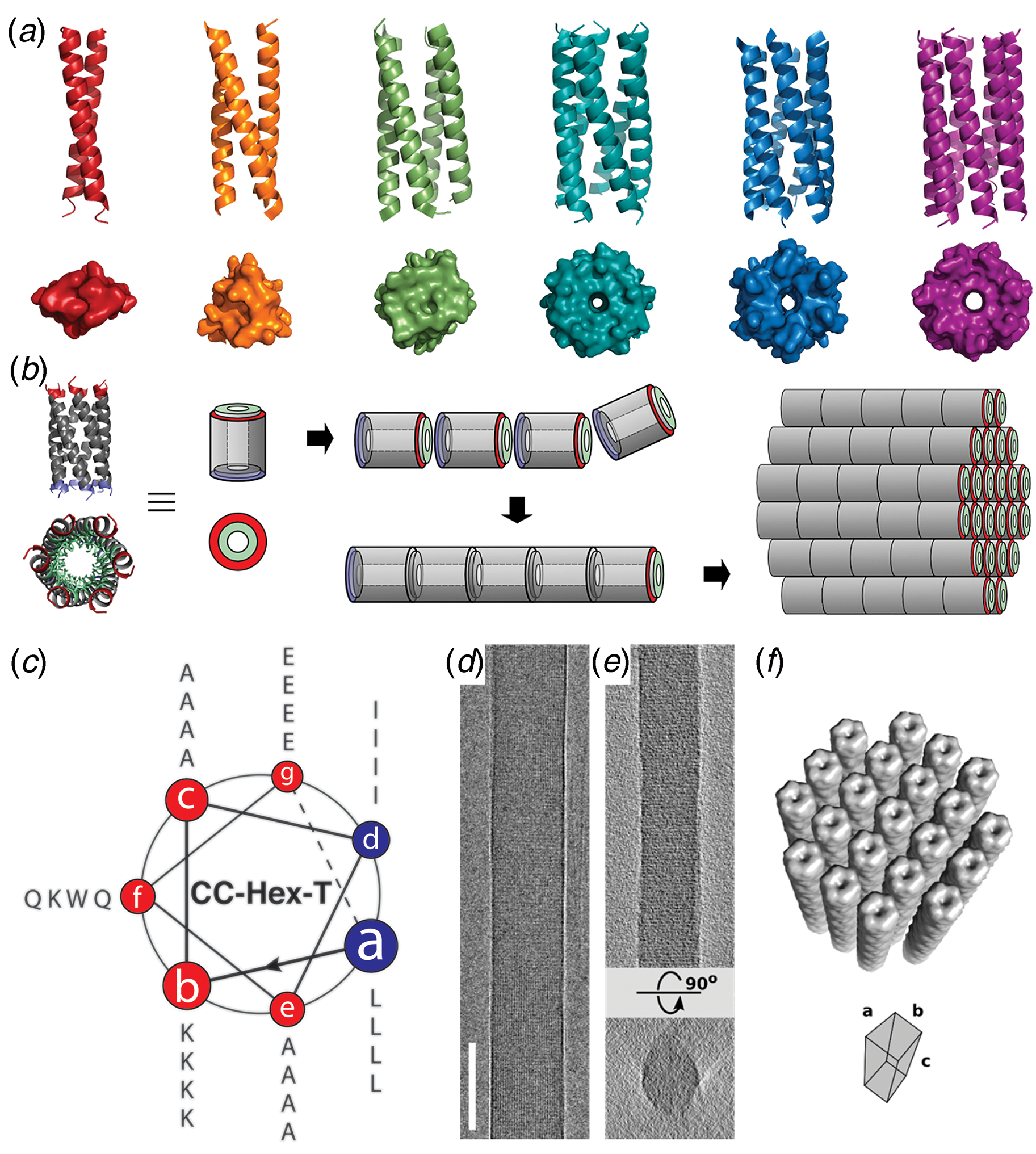
The coiled-coil assemblies described thus far display the classical architecture in which the individual helices were aligned nearly parallel to the superhelical axis (Lupas and Bassler, Reference Lupas and Bassler2017; Woolfson, Reference Woolfson2017). Tayeb-Fligelman et al. recently reported the first example of a cross-α fibril structure from crystallographic analysis of PSMα3, a short cytolytic peptide secreted from virulent strains of Staphylococcus aureus (Tayeb-Fligelman et al., Reference Tayeb-Fligelman, Tabachnikov, Moshe, Goldshmidt-Tran, Sawaya, Coquelle, Colletier and Landau2017). The helices were observed to pack in a stacked bilayer array, in which individual peptides were oriented perpendicular to the long axis of the crystallographically defined filament. Subsequently, Zhang et al. reported a series of peptides based on designed coiled-coil sequences that assembled into filaments (Zhang et al., Reference Zhang, Huang, Yang, Kratochvil, Lolicato, Liu, Shu, Liu and Degrado2018). Crystallographic analyses demonstrated that the peptides formed cross-α super-helical arrays through stacking of parallel dimers in an alternating antiparallel orientation. However, these filaments displayed limited interfaces over which KIH packing was observed between protomers.
Egelman et al. employed helical reconstruction from cryo-EM images to characterize two cross-α filaments based on coiled-coil peptide sequences (Egelman et al., Reference Egelman, Xu, Dimaio, Magnotti, Modlin, Yu, Wright, Baker and Conticello2015). Two 29-residue peptide sequences were designed based on a type 3 coiled-coil architecture, first proposed by Walshaw and Woolfson (Reference Walshaw and Woolfson2001), from analysis of the coiled-coil region of the bacterial protein tolC and subsequently observed in bacteriophage transit tubes (Koronakis et al., Reference Koronakis, Sharff, Koronakis, Luisi and Hughes2000; Sun et al., Reference Sun, Young, Zhang, Boudko, Fokine, Zbornik, Roznowski, Molineux, Rossmann and Fane2014). To decrease the degree of curvature and create a larger nanotube, residues at the interface between protomers (c- and d-positions, Fig. 19a and b) were replaced with larger isoleucine and leucine, and residues on the outside (a- and f-positions) were exchanged for smaller alanine. Charged residues were substituted at the b- and e-positions to increase solubility and direct heterotypic facial interaction between adjacent helices in a parallel orientation. The resulting peptides, Form I and Form II, differed only in the presence of arginine versus lysine at identical positions within the respective sequences.
(a, b) Helical wheel diagrams indicating the heptad register of the Form I and Form II peptide sequences. (c, d) Representative cryo-EM images of the Form I (c) and Form II (d) nanotubes. (e, f) Atomic models fit into the 3D reconstructions of the Form I (e) and the Form II (f) nanotubes derived from cryo-EM analysis. Reprinted with permission from Egelman et al. (Reference Egelman, Xu, Dimaio, Magnotti, Modlin, Yu, Wright, Baker and Conticello2015), Structure, 23(2), 280–289.
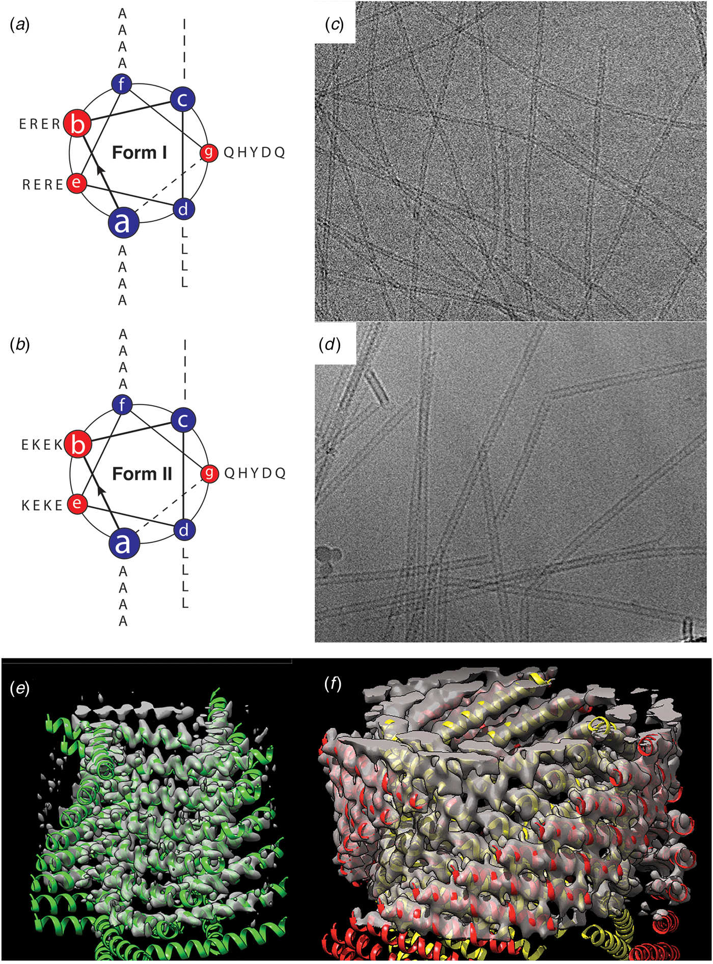
The Form I and Form II peptides assembled into nanotubes from buffered aqueous solution at ambient temperature. CD spectropolarimetry indicated the presence of an α-helical conformation, which was consistent with the formation of a coiled-coil assembly. However, conventional TEM and SAXS measurements provided evidence that the diameter of the Form II filaments (~120 Å) was double the diameter of the Form I filaments (~60 Å). These results suggested that the two structures must be different despite the similarity between the two peptide sequences. Cryo-EM analysis with direct electron detection was employed to generate 2D projection images for helical reconstruction of the thin filaments (Fig. 19c and d). Helical reconstruction afforded distinct atomic models for the Form I and Form II filaments (Fig. 19e and f). This work represented an early success for single-particle cryo-EM structural analysis of designed peptide filaments.
While similar in sequence and identical in apparent secondary structure, Forms I and II assembled into different quaternary structures. The structure of the Form I nanotubes (PDB: 3J89) was solved at 3.6 Å resolution and was based on a left-handed, 1-start helix (~4.1 subunits per turn). The asymmetric unit corresponded to a single α-helix, which resulted in formation of a single-walled nanotube with a helical pitch of ca. 9.0 Å and a helical twist of ca. −88°. The Form I nanotube has a nearly square cross section in which the subunits were arranged into four protofilaments that coincided with the right-handed 4-start helices of the nanotube.
In contrast, the initial reconstruction of the Form II nanotube afforded a density map at relatively low resolution (~7 Å), but clearly displayed an asymmetric unit based on a pair of α-helices that resulted in a double-walled nanotube. Subsequent cryo-EM data collection on Form II filaments resulted in a higher-resolution (~4.2 Å) reconstruction, which resulted in a more reliable atomic model (PDB: 6WL8). The structure was based on a right-handed 1-start helix with a helical pitch of 5.6 Å and a helical twist of 124.4°. The individual protofilaments within the nanotube corresponded to the right-handed 3-start helices. The reconstruction had sufficient resolution to determine that the pair of helices in the asymmetric unit was oriented in parallel across the inner-outer interface of the bilayer.
The primary difference between the Form I and Form II assemblies resided in the nature of the cohesive interactions between protofilaments that correspond to the cross-α helical stacks. The stacking interactions along a protofilament were quite similar between the two assemblies and corresponded to the KIH interactions that are typically observed for coiled-coil motifs. In contrast, the interactions between protofilaments involved side-to-end helical association and end-to-end association for Form I and Form II, respectively. The Form I interactions involved a pair of arginine residues, R13 and R17, that capped the C-terminus of a helix on an adjacent protofilament through a network of hydrogen-bonding interactions. This unique interaction, which was designated as an arginine clasp, does not appear to have been evolutionarily sampled as an interaction motif between helices in native protein structures (Wang et al., Reference Wang, Gnewou, Modlin, Beltran, Xu, Su, Juneja, Grigoryan, Egelman and Conticello2021a). Lateral association between protofilaments in the Form II structure was based on a much weaker hydrogen bonding between Q29 and Q1 on structurally adjacent helices at the concave (inner) interface. The two structures can be interconverted through limited mutagenesis at these structurally critical positions within the respective peptide sequences (Egelman et al., Reference Egelman, Xu, Dimaio, Magnotti, Modlin, Yu, Wright, Baker and Conticello2015).
The arginine clasp motif defined the number of protofilaments in the Form I structure and consequently its diameter. A series of peptides based on the Form I sequence was synthesized in which the length of the peptide was varied from two to five heptad repeats (Fig. 20a) (Wang et al., Reference Wang, Gnewou, Modlin, Beltran, Xu, Su, Juneja, Grigoryan, Egelman and Conticello2021a). Each sequence preserved a single arginine clasp motif within the most N-terminal heptad. This peptide series was observed to self-assemble into high aspect-ratio filaments. Cryo-EM imaging (Fig. 20b–d) was employed to determine the structures of the two-heptad (15-10-3), four-heptad (29-24-3), and five-heptad (36-31-3) peptides at resolutions 4.2, 4.1, and 4.0 Å, respectively (PDB: 6WKX, 6WKY, and 6WL0). In combination with the Form I structure, these filaments represent a homologous series in which the arginine clasp interaction is conserved between laterally associating protofilaments within the respective structures. However, the number of protofilaments within the respective structures depended on the length of the peptide and decreased with an increasing number of heptad repeats (Fig. 20).
(a) Peptide sequences of Form I variants in which the position of the arginine clasp motif is highlighted in red. Structural analyses of the 15-10-3 (b), the 29-24-3 (c), and the 36-31-3 (d) filaments. Representative cryo-EM images are shown on the left (scale bar = 50 nm). Atomic models fit into the respective 3D reconstructions are in the middle. Top views of the respective assemblies are shown on the right. Reproduced under the Creative Commons License from Wang et al. (Reference Wang, Gnewou, Modlin, Beltran, Xu, Su, Juneja, Grigoryan, Egelman and Conticello2021a). Nature Communications, 12(1), 407.
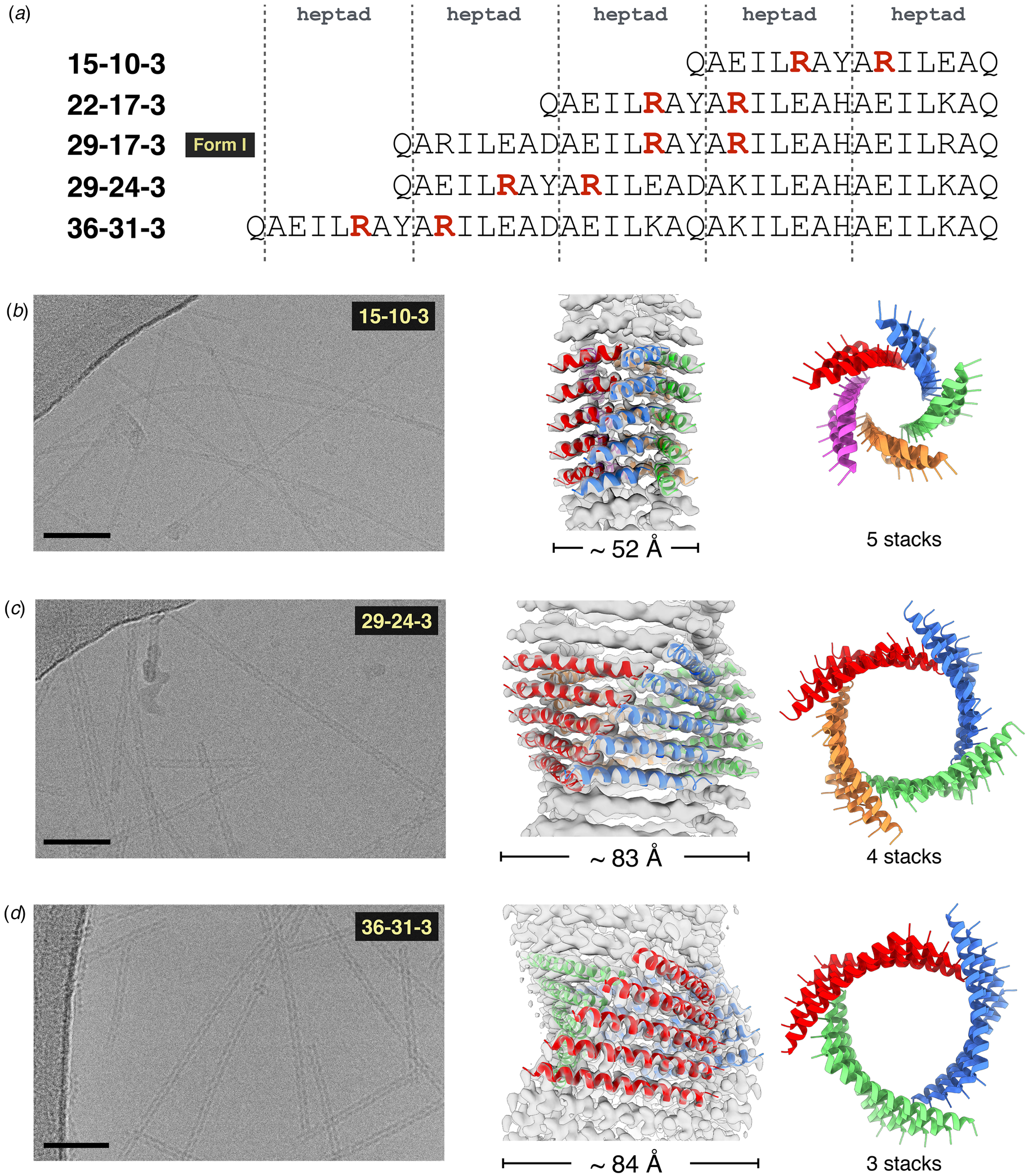
Finally, alternative strategies can be conceived for the fabrication of nanotubes from self-association of discrete helical bundles. Zhang et al. reported the computational design of antiparallel four-helix bundles that could self-associate into crystalline 2D assemblies of defined layer symmetry through optimization of protein–protein interactions at the interfaces between the tetrameric protomers (Zhang et al., Reference Zhang, Polzer, Haider, Tian, Villegas, Kiick, Pochan and Saven2016). However, in lower pH buffers (10 mM sodium acetate, pH 4.5), one of these peptides assembled into nanotubes of defined diameter (Tian et al., Reference Tian, Polzer, Zhang, Kiick, Saven and Pochan2018). Multiple analytical measurements (TEM, SAXS, AFM, cryo-EM, and STEM) supported the formation of apparently homogeneous nanotubes, although the nature of the cohesive interactions between tetramers remains speculative in the absence of high-resolution structural information. The tubes were observed to slowly convert into sheets over extended periods of time. The sheet form was dominant at neutral pH, which suggested that the tubes represented a kinetic product. A similar pH-dependent transition between sheets and scrolled tubes was reported for a series of designed collagen-mimetic peptides (Merg et al., Reference Merg, Touponse, Genderen, Blum, Zuo, Bazrafshan, Siaw, Mccanna, Brian Dyer, Salaita, Abrahams and Conticello2020). These data suggested that preformed supercoiled peptide motifs could serve as protomers for the creation of shape-shifting nanomaterials that could toggle between sheet-like and tubular forms. Further structural characterization at high-resolution would enable a more detailed understanding regarding the supramolecular structural parameters that underlie these morphological transitions.
Tandem repeat assemblies
Tandem repeat proteins (TRPs) consist of concatenated sequences of relatively short secondary structure motifs, e.g. α-helical hairpins, that form extended folded structures displaying helical symmetry (Kobe and Kajava, Reference Kobe and Kajava2000; Kajava, Reference Kajava2012). Within a given TRP class, sequence features that mediate interactions between the repeats are often highly conserved, while non-structurally integral amino acid positions are usually hypervariable. These protein families represent attractive substrates for the design of synthetic helical assemblies, especially for roles in substrate recognition and binding.
One of the most studied classes of TRPs is derived from the tetratricopeptide repeat (TPR) motifs, which are naturally occurring TRPs based on a helix–turn–helix structural motif. Regan and co-workers identified the consensus repeat sequence for a 34 amino acid TPR motif (Main et al., Reference Main, Xiong, Cocco, D'Andrea and Regan2003). Synthetic concatemers based on different lengths of this consensus TPR (CTPR) were prepared and structurally characterized. Single-crystal X-ray diffraction analysis of CTPR8 indicated that it crystallized in three different unit cells corresponding to different space groups with distinct crystallographic symmetry elements (PDB: 2AVP, 2FO7, and 2HYZ) (Kajander et al., Reference Kajander, Cortajarena, Mochrie and Regan2007). In each case, the CTPR units stacked in a polar, head-to-tail fashion to form a continuous right-handed superhelix. The main-chain atoms within the respective CTPR subunits of the three crystal structures were superimposable. The right-handed superhelix consisted of eight TPR motifs per helical turn and therefore a CTPR8 polypeptide corresponded to a single turn of the superhelix. The crystal structure of the longer CTPR20 indicated that it adopted an identical helical structure with respect to individual superhelical filaments within stacked unit cells along the central axis of the assembly. SAXS measurements of CTPR8 in aqueous buffers did not provide evidence for the formation of persistent filamentous structures in solution, although the local helical conformation was conserved. However, Grove and coworkers demonstrated that a concatemer of different length, CTPR18, could spontaneously self-associate into oriented thin solid films that display multi-scale order and stimulus responsive behavior (Carter and Grove, Reference Carter and Grove2015, Reference Carter and Grove2018).
In an attempt to create synthetic helical filaments based on minimal-length tandem repeat motifs, Conticello and coworkers (Hughes et al., Reference Hughes, Wang, Wang, Kreutzberger, Osinski, Orlova, Wall, Zuo, Egelman and Conticello2019) designed two peptides based on sequences derived from a leucine-rich repeat variant (LRV) (Peters et al., Reference Peters, Stowell and Rees1996) and a thermostable HEAT repeat (PBS_HEAT) (Urvoas et al., Reference Urvoas, Guellouz, Valerio-Lepiniec, Graille, Durand, Desravines, Van Tilbeurgh, Desmadril and Minard2010) sequences, respectively. While single-repeat motifs have been postulated to be thermodynamically unstable toward self-association at ambient temperature, the resulting sequences, LRV_M3Δ1 and HEAT_R1, assembled into high aspect-ratio helical filaments in aqueous buffers over a wide pH range (Fig. 21). Synchrotron SAXS measurements on solutions of the respective peptides confirmed the presence of narrow diameter filamentous assemblies. Cryo-EM was employed to investigate the structures of the two filaments derived from these structurally related tandem repeat motifs.
Single tandem repeat motifs self-assemble into stable nanotubes. (a, d) Representative cryo-EM images of LRV_M3Δ1 (a) and HEAT_R1 (d) filaments. (Scale bar = 100 nm.) (b, e) Atomic models fit into the 3D reconstructions of the LRV_M3Δ1 (b) and HEAT_R1 (e) nanotubes. The asymmetric units are highlighted for the respective filaments in blue, which, in the case of HEAT_R1, corresponds to a dimer of peptides. (c, f) Helical net diagrams for the LRV_M3Δ1 (c) and HEAT_R1 (f) nanotubes, in which the difference in helical hand between the respective 1-start helices is apparent. The helical nets show the unrolled surface lattice viewed from the outside of the filament. From Hughes et al. (Reference Hughes, Wang, Wang, Kreutzberger, Osinski, Orlova, Wall, Zuo, Egelman and Conticello2019), Proceedings of the National Academy of Sciences of the United States of America, 116(29), 14456–14464.
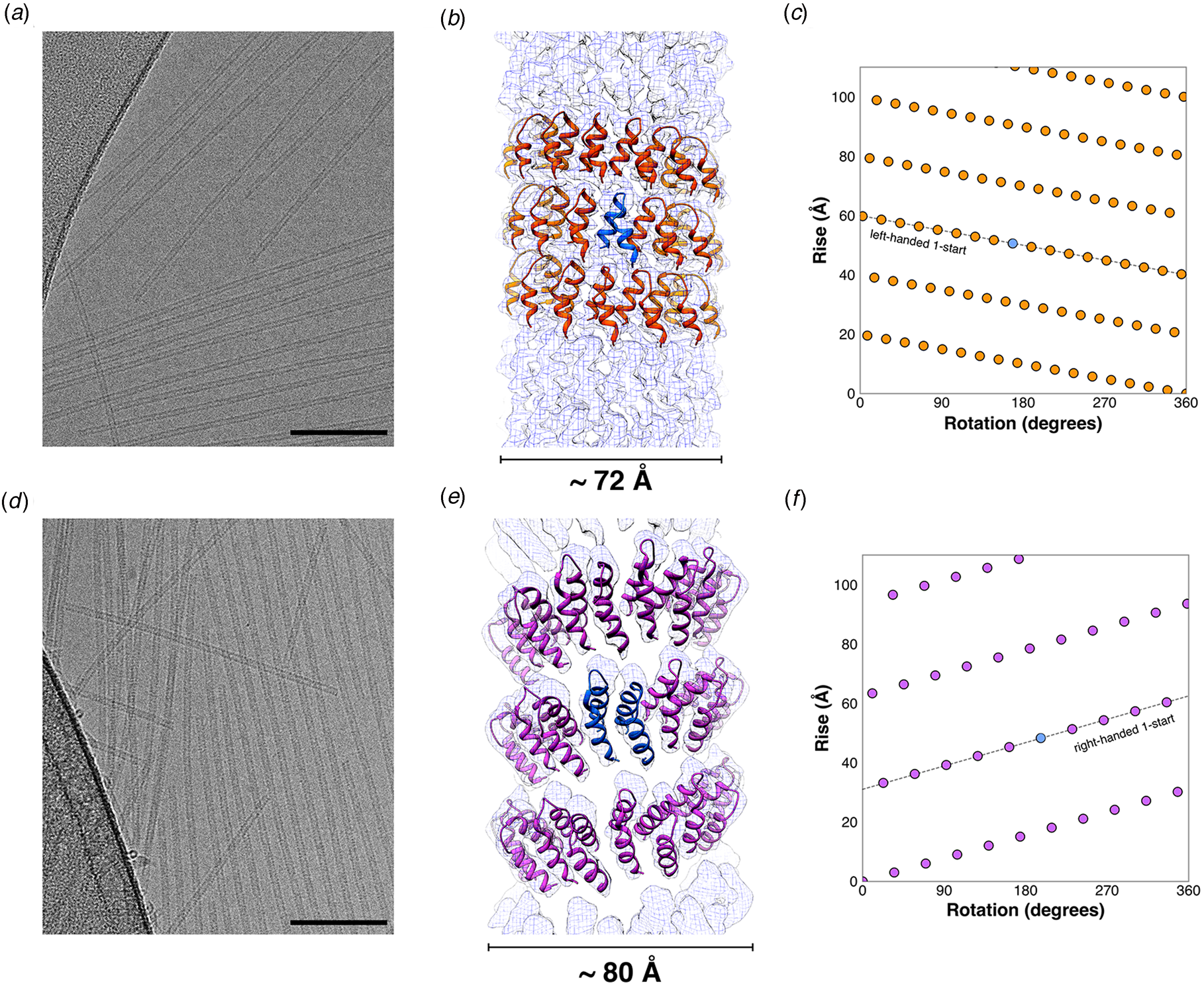
Structural analysis of the LRV_M3Δ1 filaments (PDB: 6HQE) indicated that it formed a left-handed, 1-start helix (Fig. 21a–c). The helical hand of the LRV filament differed from the native right-handed helical twist of a crystallographically characterized LRV repeat concatemer (PDB: 1LRV). In addition, while the asymmetric unit corresponded to a single-repeat motif, the repeat units adopted an α-helix–loop–α-helix conformation, which contrasted with the α-helix–loop–310-helix conformation of the tandem repeat motifs in the crystal structure of a native LRV concatemer. The lateral interaction between adjacent LRV repeat motifs stabilized the assembly along the direction of the 1-start helix of the assembly and provided the primary driving force for polymerization. The formation of the closed nanotube involved the interaction between arginine residues on protomers at the interface between adjacent turns of the helical assembly (Fig. 21b). Notably, this axial interaction buried about twice as much surface area per subunit as the HEAT_R1 filaments (vide infra).
In contrast, the structure of the HEAT_R1 filament (PDB: 6MK1) displayed right-handed 1-start helical symmetry (Fig. 21d–f) in which the periodicity was similar to the super-helical structure observed within the crystal structure of a concatemer based on a consensus PBS_HEAT repeat (PDB: 3LTJ). However, the arrangement of protomers in the HEAT_R1 filament differed from the crystal structure of the soluble concatemers. The asymmetric unit of the HEAT_R1 filament was based on non-covalent association between two peptide motifs (Fig. 21e). One helical hairpin in the asymmetric unit could be aligned with repeat units derived from PBS_HEAT motifs in the crystal structure of the synthetic concatemer. The structure of the other peptide was distinct from that of the canonical PBS_HEAT repeats due to the need to accommodate a Trp–Trp interaction between the two peptides in the asymmetric unit. PISA (proteins, interfaces, surfaces, and assemblies) (Krissinel and Henrick, Reference Krissinel and Henrick2007) analysis showed that the buried surface area of the lateral interface was significantly larger than the corresponding value for axial interface. This difference arises because of the structural distortions induced by the Trp–Trp interaction between the two peptides in the asymmetric unit. TEM imaging indicated that the HEAT_R1 filaments would frequently unwind on the grid, presumably because of the weak axial interaction between adjacent helical turns of the assembly. While these results confirmed that stable helical filaments could be constructed from self-assembly of tandem repeat sequences, the structural analysis also highlighted the plasticity of helical symmetry within supramolecular assemblies. Slight differences in local interactions and peptide conformation led to differences in peptide packing at the lateral and axial interfaces within a filament, which altered the helical symmetry of the assembly vis-à-vis the corresponding soluble oligomers.
Shen et al. reported successful de novo design of helical filaments (DHFs) derived from computationally optimized synthetic tandem repeat oligomers based on helix–turn–helix motifs (Shen et al., Reference Shen, Fallas, Lynch, Sheffler, Parry, Jannetty, Decarreau, Wagenbach, Vicente, Chen, Wang, Dowling, Oberdorfer, Stewart, Wordeman, De Yoreo, Jacobs-Wagner, Kollman and Baker2018). The design algorithm screened for self-assembling proteins by selecting an arbitrary asymmetric protomer and randomly sliding an identical protomer into contact. The screen employed 15 structurally distinct, computationally designed folded protomers, which resulted in 124 target sequences that were expressed in Escherichia coli. Filamentous nanomaterials were observed from expression of 34 of these synthetic constructs. Cryo-EM was employed to analyze the structure of the six most promising filaments. The helical reconstructions ranged in resolution from 3.4 to 7.8 Å (Fig. 22). The geometry of the experimentally determined structural interfaces matched well to the computational designs for four of the six designed filaments, while the overall supramolecular architectures were retained for all of the designs. Despite these observations, even the most accurate computational predictions cannot recapture helical symmetry precisely since slight differences in interfacial interactions may lead to changes in helical symmetry (vide supra). The latter represents a known but unappreciated phenomenon in the design of helical peptide and protein assemblies (Egelman et al., Reference Egelman, Xu, Dimaio, Magnotti, Modlin, Yu, Wright, Baker and Conticello2015; Lu et al., Reference Lu, Li, Yin, Ruan, Yu, Egelman and Wu2015). Nevertheless, this observation does not diminish the impact of these results, which represent the most reliable and accurate predictive design of helical filaments that has been reported thus far.
Computational design of helical filaments from designed TRPs. Left to right: Computational models, representative cryo-EM images, cryo-EM-derived atomic models, and structural overlays between the computational model and experimental structure for designed helical filaments DHF58 (a), DHF119 (b), DHF91 (c), DHF46 (d), DHF79 (e), and DHF38 (f). From Shen et al. (Reference Shen, Fallas, Lynch, Sheffler, Parry, Jannetty, Decarreau, Wagenbach, Vicente, Chen, Wang, Dowling, Oberdorfer, Stewart, Wordeman, De Yoreo, Jacobs-Wagner, Kollman and Baker2018), Science, 362(6415), 705–709. Reprinted with permission from AAAS.
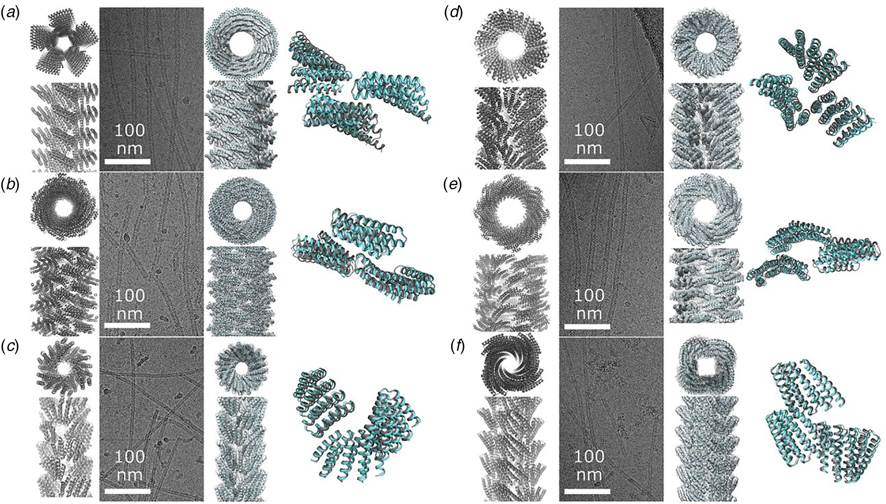
The stability and persistent tertiary structures of the synthetic protomers enabled rational control of filament structure as well as the dynamics of filament assembly. For one designed helical filament, DHF58 (PDB: 6E9T), the number of repeats in the concatemer was employed to control filament width, while preserving the designed inter-protomer interfaces (Fig. 23). Kinetic analysis of another designed filament, DHF119 (PDB: 6E9Z), indicated that the self-assembly process was concentration-dependent and reversible below a ceiling concentration. Filament disassembly resulted upon dilution below this critical concentration. Synthetic capping proteins were designed in which one interface in the protomer was prevented from self-association. Addition of these capping agents prevented further addition at the blocked terminus, but also initiated a concentration-dependent disassembly of the filaments due to the dynamically reversible association/dissociation of kinetically competent protomers. Green fluorescent protein-tagged monomers of DHF58 could assemble into filaments in live and phage-lysed E. coli expression strains, which suggested that these assemblies could be employed for in cellulo applications.
Diameter of designed helical filament DHF58 can be controlled through the number of tandem repeats in the protomer. (a) Cross sections and side views of computational models based on the four-repeat cryo-EM structure. The number of repeats (n) is shown at the top. (b) Representative negative stain electron micrographs of the corresponding helical filaments. (c) 2D-class averages derived from electron micrographs of the respective filaments. From Shen et al. (Reference Shen, Fallas, Lynch, Sheffler, Parry, Jannetty, Decarreau, Wagenbach, Vicente, Chen, Wang, Dowling, Oberdorfer, Stewart, Wordeman, De Yoreo, Jacobs-Wagner, Kollman and Baker2018), Science, 362(6415), 705–709. Reprinted with permission from AAAS.
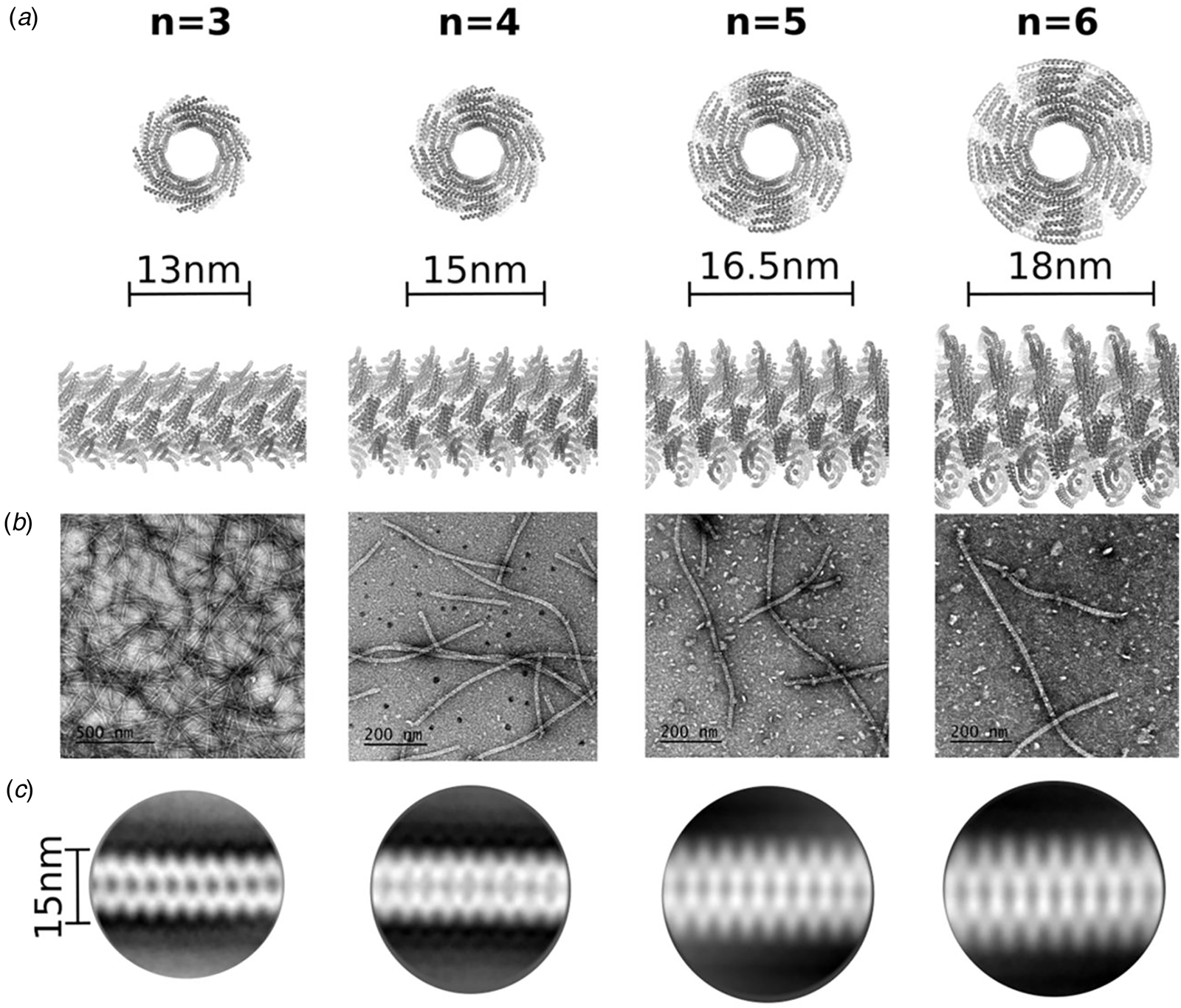
While TRPs based on α-helical motifs have been more extensively examined for the fabrication of synthetic peptide and protein filaments, β-sheet tandem repeat motifs commonly occur as structural elements in native proteins as well (Kajava and Steven, Reference Kajava and Steven2006). These β-solenoid or β-helix motifs consist of two, three, or four β-strands that are linked through short turn or β-arc segments. The individual repeat motifs often occur as extended concatemers within native proteins, which form the turns of a parallel cross-β helix. Stacking of the repeats is mediated through the formation of hydrogen-bonded β-sheet along the helical axis of the structure and is reinforced through hydrophobic interactions that occur within the core of the helix. In contrast to cross-β filaments such as amyloids, uncontrolled polymerization in native β-solenoid proteins is prevented through the presence of N- and C-terminal globular domains that prevent end-to-end association.
Toney and co-workers (Peralta et al., Reference Peralta, Karsai, Ngo, Sierra, Fong, Hayre, Mirzaee, Ravikumar, Kluber, Chen, Liu, Toney, Singh and Cox2015; Peng et al., Reference Peng, Peralta and Toney2017b, Reference Peng, Peralta, Cox and Toney2020), have employed native β-solenoid domains as the starting point for the design of synthetic β-helical filaments. Manual and computational designs were used separately or in combination to create discrete-length concatemeric sequences based on two-strand and three-strand solenoid repeats. The proteins were obtained from bacterial expression from synthetic genes. To promote assembly of extended filaments, the corresponding proteins lacked N- and C-terminal capping groups. Remarkably, despite their strong aggregation potential, the β-helical proteins could be prepared and purified in reasonable yield (30–40 mg l−1 of culture) using recombinant protein expression in an E. coli bacterial host.
Protein solutions were meta-stable in the unassociated state but could be driven to self-assemble through incubation at 37 °C. TEM and AFM analysis of the assembled proteins indicated the presence of filaments of similar diameter to the parent β-helices. The CD spectra were consistent with the presence of a high content of β-sheet conformation. The resulting filaments displayed remarkable resistance to elevated temperature, organic solvents, chemical denaturants, and were stable over a wide pH range. In addition, nanomechanical measurements and molecular dynamics simulations provided evidence that mechanical properties of the synthetic filaments, e.g. ultimate tensile strength and Young's modulus, were similar to the corresponding values for other β-sheet materials including amyloids and spider silk (Peng et al., Reference Peng, Parker, Peralta, Ravikumar, Cox and Toney2017a). These results suggested that β-solenoid assemblies present attractive targets for rational design of novel nanomaterials.
Most of the designed filaments described thus far have been derived from relatively simple structural motifs. As protein engineering and computational design efforts advance, more structurally complex subunits may be considered as substrates for the design of synthetic protein filaments. Biological systems often employ globular protein domains as building blocks for the assembly of filaments including F-actin, microtubules, etc. Recent studies suggested that filamentation may represent a mechanism to regulate protein function, including enzymatic catalysis (Lynch et al., Reference Lynch, Hicks, Shepherd, Endrizzi, Maker, Hansen, Barry, Gitai, Baldwin and Kollman2017, Reference Lynch, Kollman and Webb2020).
In this vein, Kaltofen et al. (Reference Kaltofen, Li, Huang, Serpell, Barth and Andre2015) reported the computational design of a small self-assembling βαβ domain (Fig. 24). While technically neither a globular domain nor a tandem repeat motif, this small modular protein fold was constructed from a pair of β-strands that were connected via turns to an α-helix (Fig. 24a). The sequence of the β-strand motifs was derived from a self-associating heptapeptide in the N-terminal prion domain of the Saccharomyces cerevisiae termination factor Sup35 (Balbirnie et al., Reference Balbirnie, Grothe and Eisenberg2001; Nelson et al., Reference Nelson, Sawaya, Balbirnie, Madsen, Riekel, Grothe and Eisenberg2005). The self-assembly behavior of this oligopeptide sequence was associated with manifestation of the [PSI+] prion phenotype in S. cerevisiae (Cox et al., Reference Cox, Tuite and Mclaughlin1988). The amino acid residues responsible for the polar zipper interface between β-sheets were retained, but the remainder of the structure was designed de novo using Rosetta (Huang et al., Reference Huang, Ban, Richter, Andre, Vernon, Schief and Baker2011; Leaver-Fay et al., Reference Leaver-Fay, Tyka, Lewis, Lange, Thompson, Jacak, Kaufman, Renfrew, Smith, Sheffler, Davis, Cooper, Treuille, Mandell, Richter, Ban, Fleishman, Corn, Kim, Lyskov, Berrondo, Mentzer, Popovic, Havranek, Karanicolas, Das, Meiler, Kortemme, Gray, Kuhlman, Baker and Bradley2011). Self-assembly was proposed to occur through dimerization of the computationally designed βαβ motif at the β-sheet interface and subsequent elongation through end-to-end propagation of the β-sheet in a cross-β orientation (Fig. 24b and c). The computationally designed peptide, βαβZip, was synthesized using solid-phase synthesis (Fig. 24d). TEM imaging indicated the presence of high aspect-ratio filaments of apparent width that compared well with the lateral dimensions of the computational model. FTIR spectroscopy and CD spectropolarimetry measurements agreed with a mixed α/β conformational population. While a high-resolution structure was not available to compare to the atomistic model, X-ray fiber diffraction analysis performed on oriented filaments provided evidence for a cross-β structure that agreed well with the computational model.
De novo design of self-assembling βαβ peptides. (a) The computational design is based on the crystal structure of the amyloidogenic heptapeptide sequence GNNQQNY derived from the sup35 N-terminal prion domain. A loop–helix–loop segment constructed using flexible backbone design connects two β-strands with backbone conformations taken from the sup35 peptide. (b) Cross section of the computational model of the fibril in a view perpendicular to the fiber axis. The interactions between the two layers of sheets are stabilized by a steric zipper interface formed by interdigitating side chains at the strand interfaces. (c) Structural model the peptide filament with estimated lateral dimensions for a cross section. (d) Sequences of computationally designed peptides βαβZip and βαβZip2. Residues highlighted in green correspond to the steric zipper interface, while residues highlighted in red correspond to the α-helix. From Kaltofen et al. (Reference Kaltofen, Li, Huang, Serpell, Barth and Andre2015), Journal of Molecular Biology, 427(2), 550–562. Reprinted with permission from Elsevier.
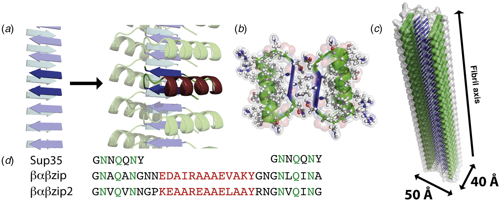
Foldamer-based helical assemblies
Until now, peptide assemblies derived from discrete length oligomeric α-amino acid sequences, corresponding to native polyamide backbones, have been discussed exclusively. However, these sequences do not represent the sole plausible substrates for design of oligomers competent for self-assembly into structurally defined filaments. Recently, the design of peptido-mimetic foldamers (Goodman et al., Reference Goodman, Choi, Shandler and Degrado2007) has been explored in order to evaluate for the potential formation of structurally defined supramolecular assemblies (Misra et al., Reference Misra, Rudnick-Glick and Adler-Abramovich2021). While sequence–structure correlations are less well-defined for covalent oligomers based on alternative backbone chemistries, foldamer assemblies offer several potential advantages as substrates for the fabrication of biomimetic helical filaments and nanotubes. The primary consideration that has driven investigation into foldamer assemblies is their potential resistance to proteolytic cleavage in a biological environment as well as a lowered propensity to elicit an immune response. Moreover, synthetic foldamers exhibit a rich structural chemistry that differs from that of conventional α-amino acid oligomers, which may lead to different supramolecular architectures that may be more suited for a particular downstream application.
Polypeptoids, or polymers of N-substituted glycines, have been extensively studied as building blocks for construction of supramolecular assemblies (Sun and Zuckermann, Reference Sun and Zuckermann2013). Unlike natural proteins they cannot be overexpressed in bacteria, but the chemical synthesis of peptoids is no more difficult than solid-phase peptide synthesis (Culf and Ouellette, Reference Culf and Ouellette2010). A diverse range of quaternary structures have been prepared from self-assembly of sequence-specific peptoids (Nam et al., Reference Nam, Shelby, Choi, Marciel, Chen, Tan, Chu, Mesch, Lee, Connolly, Kisielowski and Zuckermann2010), but here we focus on the design of filamentous assemblies. Two research groups independently demonstrated that block-like peptoid oligomers (Xuan and Zuckermann, Reference Xuan and Zuckermann2020) based on sequence-encoded contour-length amphiphilicity could self-assemble into filamentous nanomaterials. Similar self-assembly behavior was observed for block-like peptide sequences that display contour-length amphiphilicity (Van Rijt et al., Reference Van Rijt, Ciaffoni, Ianiro, Moradi, Boyle, Kros, Friedrich, Sommerdijk and Patterson2019).
Zuckermann and coworkers described a series of peptoid polymers, (pNdc)n-b-(pNte)n (n = 9, 13, 18), that displayed an AB-type amphiphilic block copolymer architecture (Sun et al., Reference Sun, Jiang, Lund, Downing, Balsara and Zuckermann2016). The N-substituents of the respective blocks had identical length, i.e. number of non-hydrogen atoms, and linear architecture, but differed significantly in polarity (Fig. 25a and b). The poly-N-decylglycine (pNdc) A-block was hydrophobic in character, while the poly-N-2-(2-(2-methoxyethoxy)ethylglycine) (pNte) B-block was hydrophilic in nature. The amphiphilic block peptoids self-assembled from a mixed solvent system into structurally well-defined nanotubes. SAXS, TEM, cryo-EM, and cryo-electron tomography (cryo-ET) provided evidence that the nanotubes displayed an unusual supramolecular architecture. The peptoid backbone was arranged circumferentially around the periphery of the nanotubes in an orientation perpendicular to the long axis of the nanotube (Fig. 25c–e). The side chains projected along the tube axis but segregated into separate hydrophilic and hydrophobic domains, which resulted in a regular pattern of stripes along the contour length of the nanotube. The packing of peptoids within the tubes resembled the stacking of tiles. The tiles were composed of side chains in which the uniform length of the hydrophilic and hydrophobic substituents was proposed to abet the ordered stacking. Three different peptoid block polymers were prepared in which the A and B block lengths were identical in the number of monomers (n = 9, 13, and 18). In every case, the axial periodicity of 24 Å was conserved in the corresponding assemblies, although the diameter of the tubes varied depending on the peptoid sequence (Fig. 25f).
Amphiphilic peptoids block copolymer tiles self-assemble into hollow nanotubes. (a) Sequence and chemical structure of pNdc18-b-pNte18. (b) Schematic depiction of the structure of pNdc18-b-pNte18 tile in which the hydrophobic and hydrophilic domains are highlighted in green and blue, respectively. The gray arrow indicates the N to C chain trajectory. (c) Schematic representation of the packing of four layers of peptoid tiles within the proposed nanotube structures. (d) Cross section of a four-layer nanotube segment with depiction of side-chain arrangement and the stacking repeat distance. (e) Schematic representation of the proposed nanotube structure with amphiphilic tile packing indicated. (f) Cross-sectional view of the proposed packing of amphiphilic tiles for three peptoid polymers with approximate tube diameter for each cross section. Reprinted with permission from Sun et al. (Reference Sun, Jiang, Lund, Downing, Balsara and Zuckermann2016), Proceedings of the National Academy of Sciences of the United States of America, 113(15), 3954–3959.
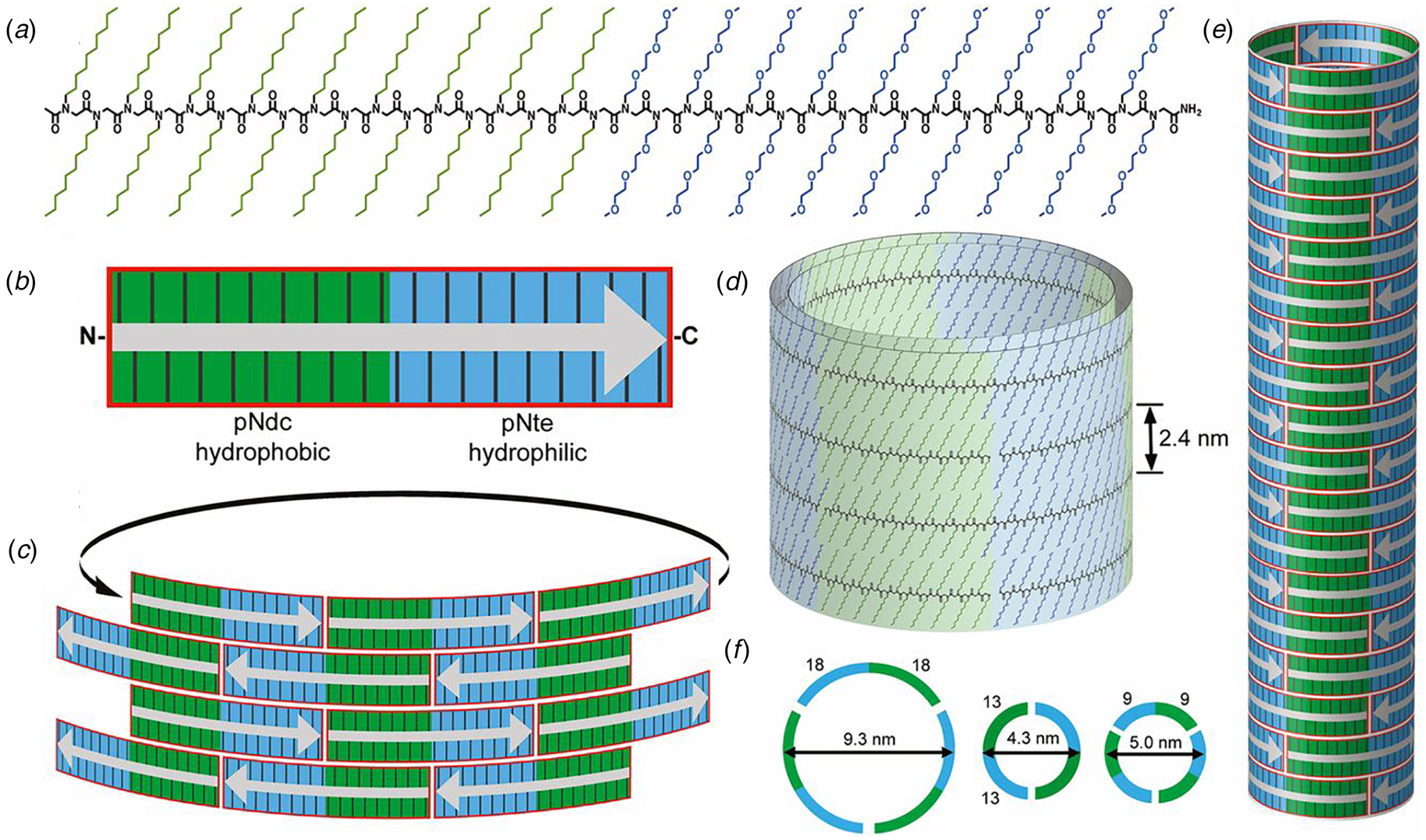
In contrast, Chen and co-workers described a class of peptoid block copolymer amphiphiles, (pNce)6-b-(pNbpm)n (n = 5, 6, 7) (Fig. 26a and b) in which the length of the hydrophobic block was varied (Jin et al., Reference Jin, Ding, Wang, Song, Liao, Newcomb, Wu, Tang, Li, Lin, Yan, Jian, Mu and Chen2018). Self-assembly of these peptoid polymers from a mixed solvent system afforded mechanically robust, crystalline nanotubes. TEM analysis indicated that the self-assembly process involved a structural evolution from particles to ribbons to tubes. The wall thickness, diameter, and mechanical properties of the tubes could be controlled through the sequence of the peptoid oligomers, that is, the length of the hydrophobic peptoid segment. Remarkably, the nanotubes were able to undergo a reversible pH-driven expansion and contraction of the tube diameter without any evidence for disassembly. Despite a similar contour-length amphiphilicity to the nanotubes described by Zuckermann and coworkers, these peptoid polymers were arranged in an antiparallel orientation within an amphiphilic monolayer. The peptoid backbones were proposed to be oriented radially within the nanotube rather than circumferentially as proposed for the previously described peptoid block copolymers (Fig. 26c). The hydrophobic 4-bromophenylmethyl (pNbpm) B-block substituents were buried in the monolayer core, while the polar 2-carboxyethyl (pNce) A-block segments extended from either surface. TEM measurements of the wall thickness of the tubes supported this structural model, in that the wall thickness increased as the length of the pNbpmn segment increased.
Amphiphilic peptoid oligomers (APOs) self-assemble into highly ordered, crystalline, single-walled peptoid nanotubes. (a) Sequence and chemical structure of the APOs. Hydrophilic and hydrophobic blocks are indicated in blue and magenta, respectively. (b) Schematic representation of the proposed structure of the monolayer nanotube with color-coding of the hydrophilic and hydrophobic blocks. (c) Cross-sectional representation of the proposed model for the APO2 nanotubes. The molecular packing of the peptoid protomers is depicted along with the critical distances that define the packing arrangement. Reprinted under Creative Commons License from Jin et al. (Reference Jin, Ding, Wang, Song, Liao, Newcomb, Wu, Tang, Li, Lin, Yan, Jian, Mu and Chen2018), Nature Communications, 9(1), 270.
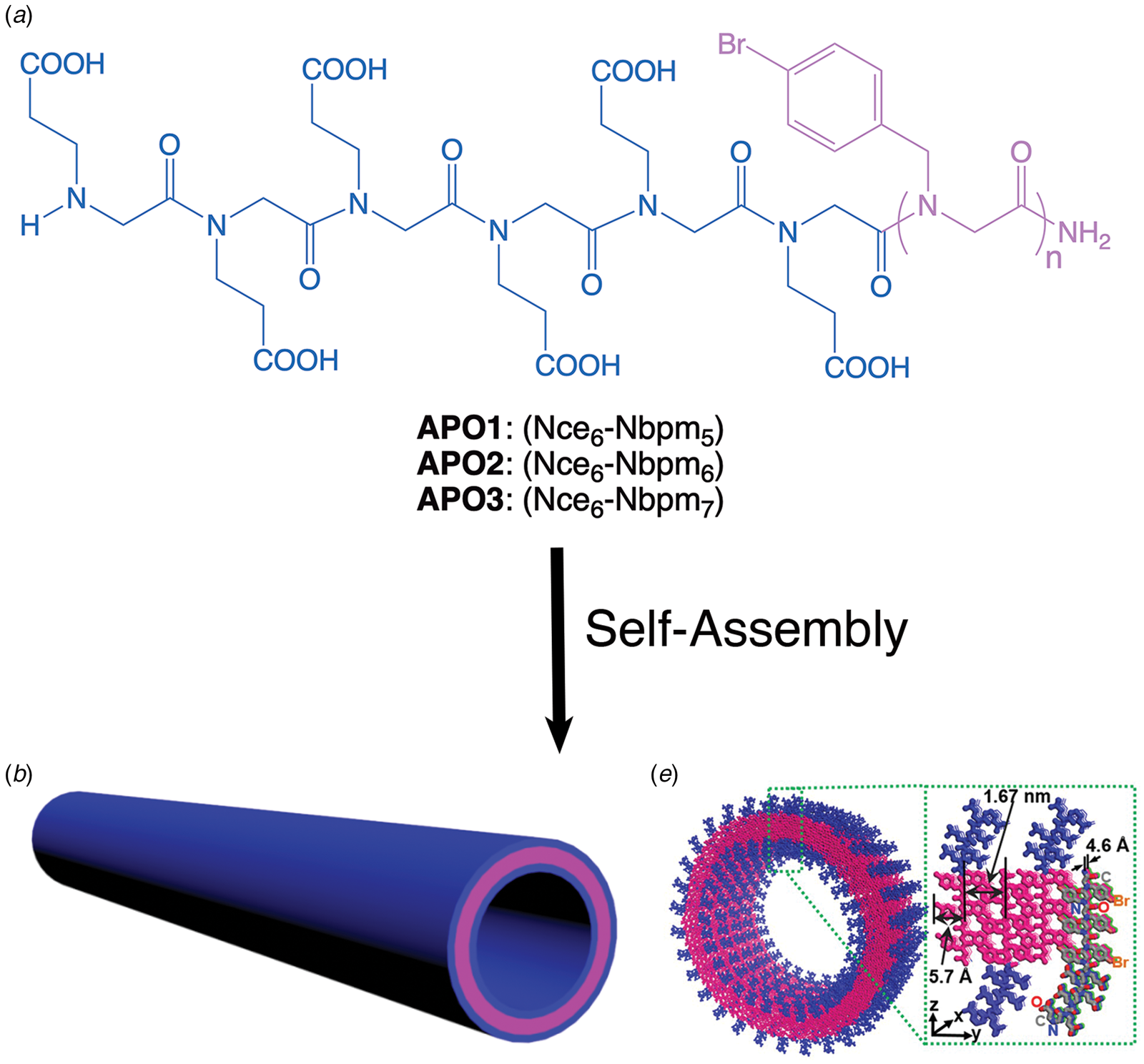
Similarly, foldamers based on aliphatic oligourea backbone (Violette et al., Reference Violette, Averlant-Petit, Semetey, Hemmerlin, Casimir, Graff, Marraud, Briand, Rognan and Guichard2005) have been demonstrated to form helical assemblies in which polar sequence patterning was observed to promote selective self-assembly (Collie et al., Reference Collie, Pulka-Ziach, Lombardo, Fremaux, Rosu, Decossas, Mauran, Lambert, Gabelica, Mackereth and Guichard2015). In contrast to the peptoids described above, the sequences of the synthetic oligoureas were designed to display conformational, that is, facial, amphiphilicity. Oligoureas had been previously demonstrated to adopt local helical secondary structures based on a pentad repeat motif, which corresponded to five monomers per two helical turns within the conformation (Fig. 27a and b). Guichard and coworkers (Collie et al., Reference Collie, Pulka-Ziach, Lombardo, Fremaux, Rosu, Decossas, Mauran, Lambert, Gabelica, Mackereth and Guichard2015) demonstrated that oligourea foldamers could assemble into either discrete hexameric helical bundles or extended nanotubes. The preference for the respective structures depended on the polar patterning of the urea side chains within the pentad-based sequence of the oligomer. Formation of an extended hydrophobic interface within a helical conformation promoted higher-order assembly of the oligourea protomers into helical assemblies.
Oligoureas can adopt amphiphilic helical secondary structures that promote self-assembly into nanotubes. (a, b) Helical wheel diagrams of the decameric (H2) and dodecameric (H5) oligourea sequences indicating the pentad registry. The facial amphiphilicity can be detected from the pattern of polar residues (red) and non-polar residues (blue). (uXaa indicates the urea analog of a canonical amino acid.) (c, e) Side and top views of the H2 nanotube derived from the corresponding crystal structure. (d, f) Side and top views of the H5 nanotube derived from the corresponding crystal structure. In each case, the individual protofilaments within the respective structures are color coded.
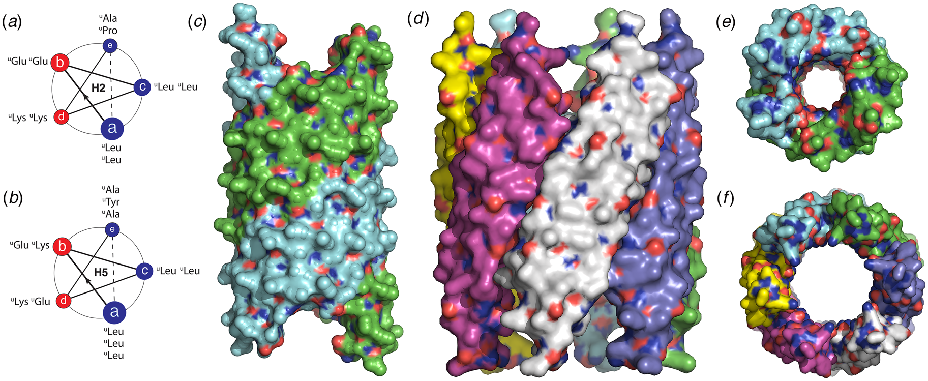
Two oligourea oligomers, decamer H2 and dodecamer H5, were synthesized based on the same polar pattern although with slightly different sequences. Single-crystal X-ray diffraction analysis of these two oligourea assemblies revealed the presence of nanotubes in both cases. The structure of H2 was based on a helical assembly with apparent C 2 symmetry in which the two protofilaments corresponded to pairs of antiparallel helices stacked along the respective 2-start helices (Fig. 27c and e). The structurally related oligourea H5 assembled into a nanotube of apparent C 6 symmetry, in which the protofilaments corresponded to the 6-start helices of the assembly (Fig. 27d and f). Conventional TEM and cryo-EM confirmed the presence of isolated nanotubes of similar dimensions to those observed crystallographically. Notably, slight changes in oligourea sequence could result in dramatic changes in the structure of the assembly, in a manner that was reminiscent of the structural plasticity often observed in peptide assemblies (Yoo et al., Reference Yoo, Collie, Mauran and Guichard2020). N-Methylation of the C-terminal amide resulted in a structural variant of the H2 decamer, H2′, which crystallized into two distinctive helical assemblies under different sets of experimental conditions. One form adopted a structure that was identical to that of H2 (Fig. 27c and e). However, under a separate set of conditions, a completely different structure was observed with a different helical periodicity although it retained C 2 symmetry.
Finally, higher-order filamentous assemblies have been observed for peptides based on non-α-amino acid sequences. Oligomers of β3-homoamino acids (Gopalan et al., Reference Gopalan, Del Borgo, Mechler, Perlmutter and Aguilar2015) have been observed to self-assemble into filaments (Del Borgo et al., Reference Del Borgo, Mechler, Traore, Forsyth, Wilce, Wilce, Aguilar and Perlmutter2013; Christofferson et al., Reference Christofferson, Al-Garawi, Todorova, Turner, Del Borgo, Serpell, Aguilar and Yarovsky2018), and form lyotropic mesophases based on filamentous assemblies (Pomerantz et al., Reference Pomerantz, Abbott and Gellman2006, Reference Pomerantz, Yuwono, Pizzey, Hartgerink, Abbott and Gellman2008, Reference Pomerantz, Yuwono, Drake, Hartgerink, Abbott and Gellman2011; Pizzey et al., Reference Pizzey, Pomerantz, Sung, Yuwono, Gellman, Hartgerink, Yethiraj and Abbott2008). The sequence determinants responsible for self-assembly have been investigated, but thus far are not well-understood due to the absence of NAR structural information. At least one example of an oligo-β3-homopeptide sequence has been reported in which formation of hollow cylindrical nanotubes was inferred on the basis of conventional TEM, low-resolution cryo-EM, and SAXS measurements (Pizzey et al., Reference Pizzey, Pomerantz, Sung, Yuwono, Gellman, Hartgerink, Yethiraj and Abbott2008; Pomerantz et al., Reference Pomerantz, Yuwono, Pizzey, Hartgerink, Abbott and Gellman2008). The polar patterning of this peptide system does not fit a conventional model that can correlate sequence with higher-order structure for the 14-helix conformation (Cheng et al., Reference Cheng, Gellman and Degrado2001) that is often observed for oligo-β3-homopeptides.
In the case of oligo-β3-homopeptide sequences, complex filamentous structures can arise even from tripeptides (Fig. 28a). Christofferson et al. reported a detailed structural analysis of assemblies derived from hydrophobic tripeptides composed of different sequence combinations of β3-homoLeu, β3-homoIle, and β3-homoAla (Christofferson et al., Reference Christofferson, Al-Garawi, Todorova, Turner, Del Borgo, Serpell, Aguilar and Yarovsky2018). X-ray fiber diffraction of oriented samples derived from assemblies of tripeptide Ac-β3[hLhIhA] (hL, homoleucine; hI, homoisoleucine; hA, homoalanine) provided evidence for a supramolecular structure in which three helical protofilaments formed a trimeric super-helix through self-association (Fig. 28b–d). X-ray diffraction data on Ac-β3[hLhIhA] were employed to benchmark molecular dynamics simulations, which were extended to the other tripeptide variants that were sequence permutants of Ac-β3[hLhIhA]. MD simulations were compared with AFM measurements and provided evidence that the supramolecular structural variations between the tripeptides originated in differences in the packing details at the helix–helix interface within the corresponding atomic models. Further confirmation of these sequence–structure correlations will await structural determination at NAR.
(a) Helical wheel diagram of tripeptide Ac-β3[hLhIhA] indicating the triad registry in a left-handed 14-helix conformation. (b) Side view of the triple-helical ribbon model of the Ac-β3[hLhIhA] filament in water. (c) Expansion of a four-layer helical stack from (b) highlighting packing at the trimeric interface in a stick representation. (d) Trimeric packing interface of a single-layer of the triple helix in which inter-residue contacts are indicated using a mesh depiction.
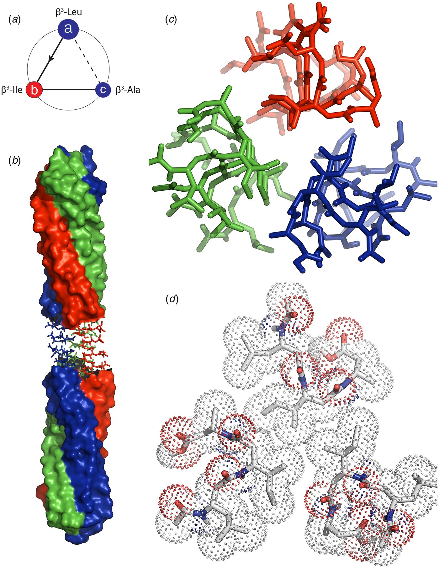
While the structural analysis of foldamer assemblies is at an early stage in its development, opportunities abound for the creation of structurally defined helical assemblies from sequences based on alternative backbone and side-chain chemistries. High-resolution structural analysis, particularly cryo-EM, offers the ability to provide insight into the sequence determinants that underlie the formation of these chemically and structurally orthogonal helical assemblies, which would enable a better understanding of the local sequence and conformational factors that underlie self-assembly behavior and provide rubrics to better guide the design of such synthetic assemblies.
Conclusions
Helical peptide assemblies offer engineering opportunities that range from peptide design to assembly functionalization. However, the rational design of synthetic helical assemblies is complicated in that minor sequence modifications within the subunits can have a considerable influence on the quaternary structure of the resultant assemblies. These effects can be difficult to predict a priori, in part due to the limited availability of high-resolution structural information on peptide and peptido-mimetic helical filaments and tubes. While the latter situation is rapidly undergoing transformative growth, reliable de novo design of helical assemblies remains a significant challenge.
NAR methods for structural determination, i.e. cryo-EM, MicroED, and ssNMR, are revolutionizing the structural analysis of peptide and protein assemblies. As these resources become more widely available, we expect to see increased information from structural studies, which will enable a better understanding of the factors that influence higher-order structure within helical assemblies. Many significant questions remain to be answered, in particular, the role of amphiphilicity in conformational selection and in orientational preferences for packing of protomers within the filaments. A better understanding of structural principles is critical to the development of synthetic helical assemblies that emulate the functional properties of native biological filaments and can be tailored for specific applications.
Acknowledgments
The authors thank Edward Egelman, Fengbin Wang, James Nowick, Louise Serpell, Mibel Aguilar, Gilles Guichard, Anil Mehta, Chunlong Chen, and Ulf Olsson for useful discussions and providing data and graphics for figures.
Financial support
This work was supported by the National Science Foundation (NSF) (V. P. C., grant number DMR-1534317).
Conflict of interest
The authors declare no competing interests.


 Open access