


1. Introduction
The presented research focuses on a future-oriented example from the field of electromobility, specifically in the automotive sector. The automotive sector has a significant impact on global CO2 emissions and offers considerable leverage for achieving sustainable development goals (United Nations, 2015). As shown by Reference Smith, Woody, Wallington, Hitt, Kim, Taub and KeoleianSmith et al. (2025) and Reference Shafique and LuoShafique and Luo (2022), electric vehicles (EVs) themselves are a response to reduce environmental impacts. EVs in combination with renewable energies can drastically reduce the environmental impacts in the use phase (Reference Xia and LiXia & Li, 2022; Reference Pipitone, Caltabellotta and OcchipintiPipitone et al., 2021). The rechargeable energy storage system (REESS) is considered as a system in which structural components, battery cells and other subsystems interact. The increased energy consumption during the manufacture of battery cells and REESS, lead to a higher environmental impact of the vehicle in production compared to internal combustion engine vehicles (Reference Xia and LiXia & Li, 2022; Reference Pipitone, Caltabellotta and OcchipintiPipitone et al., 2021). This is mainly due to the materials used (including rare earths) and their energy-intensive production processes. Although battery cells account for a large part of the environmental impact of REESS, their design and material composition are usually determined during the concept phase due to factors such as electric requirements and the battery cells themselves are not meant to transfer mechanical loads. Therefore, battery cells are treated as given boundary conditions in this research and are not subject to design changes or environmental impact assessments. In contrast, structural components such as the surrounding structures of cells in early stages of development offer considerable design freedom and directly influence material requirements, mass, cell protection, ease of disassembly, and the potential reuse or recycling of the product and its parts. These components therefore, represent effective levers for implementing circular economy-oriented design strategies. From a structural engineering perspective, high demands are placed on the structures surrounding the battery cells to prevent damage to the cells as far as possible and to guarantee passenger safety (United Nations Economic Commission for Europe, 2024). Consequently, REESS are used as an example system, as its structural components not only play a critical role in safety and functionality but also offer significant opportunities for reducing environmental impacts through design choices.
Due to political incentives, the industry has an economic interest in minimizing CO2 emissions both in production and in the use phase, as high CO2 emissions cause additional costs (Council of the European Union, 2023) and will be calculated throughout the entire life cycle of EVs (European Parliament & Council, 2019). In the use phase, there are limits for CO2 emissions that must not be exceeded, otherwise manufacturers will have to pay fines. Since 2021, the binding fleet limit in the European Union has been 95 gCO2/km and is to be reduced to 49,5 gCO2/km by 2030. (European Parliament & Council, 2019) New regulations are expected in future, such as the EU End-of-Life Vehicles Directive, which specifies a minimum requirement for the proportion of recycled materials used in vehicles (Council of the European Union, 2025). This will also create incentives for sustainable product design in industry.
This research demonstrates an industry-oriented approach how the environmental impact of a REESS can be reduced while maintaining functional requirements through combined concept evaluation, environmental assessment, and optimization. Reference Zomer, Mcaloone and PigossoZomer et al. (2022) show that climate protection measures taken by companies are crucial for the transition to a more circular economy (CE). The design of products and the services provided by companies are considered crucial for reducing greenhouse gas emissions. There is currently a lack of evidence on which design levers companies can use to achieve greenhouse gas reduction targets. Reference Zomer, de Senzi Zancul, Cauchick-Miguel and KohlbeckZomer et al. (2024) also report that practical design measures contribute significantly to reducing environmental impact. CE-oriented product design is not yet addressed through a unified approach. As a result, the design phase provides a further starting point for reducing the environmental impact caused by CO2 emissions during production.
In addition to the design process, which is based on VDI 2221, this research also includes FE analysis, environmental assessment, and structural optimization. The aim is to highlight the potential of the early design phase for improving environmental impact. To this end, the necessary terms relating to the circular economy, design strategies, environmental assessment, and their application in optimization will first be clarified. The concepts for the REESS will then be developed based on the requirements and a benchmark. A utility analysis will be carried out, incorporating criteria for sustainable concepts. Finally, structural optimization at the component level will be used as an example to optimize a battery tray, to demonstrate how CE-oriented designs can be implemented and evaluated within the context of a REESS.
2. Literature review: CE and environmental impact assessment
In recent years, the CE has become an important strategy for preventing resource waste and climate change. In contrast to the linear economy, economic growth should take place independently of limited resources, and environmental pollution should be reduced. (Reference De Oliveira, Dantas and SoaresOliveira, 2021) For example, materials should remain in the loop for as long as possible, be reused, and returned to the loop. Due to the declining quality of materials over multiple product life cycles, this is not realistic. (Reference Potting, Hekkert, Worrell and HanemaaijerPotting, 2017) Reference Kirchherr, Reike and HekkertKirchherr et al. (2017) define the CE as replacing the end of the linear economy with the strategies of reduce, reuse, and recycle. The aim is to close material cycles. Reference Linder, Sarasini and van LoonLindner et al. (2017) define the CE at the product level as part of a product that comes from an already used product that has reached the end-of-life phase. The definition by Reference Moraga, Huysveld, Mathieux, Blengini, Alaerts, Van Acker, De Meester and DewulfMoraga et al. (2019) includes a deceleration of cycles through durable products and life-extending measures, and cycles should always be closed. As a result, there are different approaches to defining the CE as a strategy that can be implemented in a variety of ways. Based on the definitions presented, this publication adopts a design-oriented understanding of CE. It is understood as a series of design strategies that aim to reduce primary resources, extend the service life of products and their parts and enable the preservation of materials at the end of the product’s life cycle.
Various publications and design strategies already exist to promote the transition to a CE. Reference Potting, Hekkert, Worrell and HanemaaijerPotting et al. (2017) describe a 9R model based on reducing the consumption of natural resources, extending service life, and utilizing raw materials. Reference Bocken, De Pauw, Bakker and Van Der GrintenBocken et al. (2016) categorize and name design strategies according to long-life products, product-life extension to close cycles, and to narrow flows. Reference Le Den, Porteron, Collin, Hvid Horup Sorensen, Herbst, Rehfeldt, Pfaff, Hirschnitz-Garbers and VeltenLe Den et al. (2020) make suggestions for the construction industry that can be analogized to the automotive industry. These include design measures such as reducing materials in the concept phase, reusing materials and components, extending service life through repair instead of replacement, and designing for easy disassembly. With the help of the design strategies, abstract CE goals can be translated into concrete design requirements, such as material reduction, disassembly options and the separation of materials. Previous studies have shown that environmental impacts can be systematically reduced through established design approaches in early product development, often supported by life cycle assessments. These approaches combine material selection, early design decisions, and strategies such as extending service life and reuse to improve environmental performance throughout the entire product life cycle. (Reference Ahmad, Wong, Tseng and WongAhmad et al., 2018; Reference Schäfer and LöwerSchäfer & Löwer, 2020; Reference Kong, Wang, Li, Tian, Li, Cai, Zhou and FuKong et al., 2022; Reference SpreaficoSpreafico, 2022).
There are also a large number of CE indicators that can be used to measure progress toward a CE (Reference Saidani, Yannou, Leroy, Cluzel and KendallSaidani et al., 2019). The environmental impact of a product is influenced by a number of factors, such as the generated or consumed resources during the manufacture, operation, and disposal of a product, as well as its waste and emissions (Reference SchumacherSchuhmacher, 2020). The scope of CE indicators varies: they can take the form of parameters, functions, or the results of complex simulations and are often based on a comparative value (Reference Moraga, Huysveld, Mathieux, Blengini, Alaerts, Van Acker, De Meester and DewulfMoraga et al., 2019). Several studies highlight that CE indicators are often formulated at a generic level (Reference Ortner, Tay and WortmannOrtner et al., 2022), which limits their ability to directly support concrete design decisions. In this publication, CE strategies are implemented through design, while the changed environmental impact of the product through different design decisions is quantified using Life Cycle Assessment (LCA). The LCA used is a standardized and internationally recognized method and is intended to show how early design decisions can be systematically assessed and guided towards reduced environmental impacts. LCA considers the entire life cycle of a product and analyzes incoming and outgoing material and energy flows (DIN EN ISO 14040, 2021).
Combining structural optimization with an assessment of environmental impact, such as LCA, enables a quantitative comparison of, material decisions and part designs. In the context of the LCA, structural optimization is not only used for lightweight design, but also for systematically researching and improving CE-oriented design variants. The target of structural optimization is to enhance the properties of a component with consideration of the given requirements (Reference SchumacherSchuhmacher, 2020). Reference Herrmann, Dewulf, Hauschild, Kaluza, Kara and SkerlosHerrmann et al. (2018) highlight the conflicting objectives, as lighter structures are actually intended to reduce environmental impact, but new materials and production processes can increase it again. Due to trade-offs between objectives and challenges in design, structural optimization is used as a tool in vehicle design. Reference Arslan and KaramangilArslan & Karamangil (2025) show an improvement in the crash behavior of the longitudinal profiles of a battery box in an EV. At present, structural optimization is already being used to reduce material usage, but it is rarely used to systematically minimize the environmental impact of a design. Therefore, assessment methods must be found to incorporate environmental impacts. There are already approaches in the literature, such as that of Reference Monetti, Martínez and MaffeiMonetti et al. (2024), which aim to optimize the development of battery systems for disassembly, material, and product recyclability. This mainly refers to the end of the product life cycle and not to resource conservation or life-extending measures. Reference Beibl, Zumach, Wehrend, Züfle, Hein, Plaumann and KrauseBeibl et al. (2024) also demonstrate the need for a link between sustainability aspects and modularization for battery packs. To the best of our knowledge, only Reference Türke, Redeker and VietorTürke et al. (2025) demonstrate the possibility of improving the initial environmental assessment of a wheel rim by applying structural optimization and CE indicators. In contrast, Reference Ortner, Tay and WortmannOrtner et al. (2022) demonstrate the optimization of the CE of products in the field of architecture in the early stages of development. These approaches can be applied to this publication.
3. Development of a REESS
This chapter describes the design process from requirements definition and concept development to structural simulation and optimization. The process was developed within the scope of this research and is positioned within established product development frameworks from the literature (Reference Pahl and BeitzPahl & Beitz, 2013; VDI (2019)). Consequently, the specific development steps, decisions, and results are presented.
3.1. Requirements specification
As a starting point in the development process, the first step is to collect the loads and minimum requirements necessary to ensure structural integrity. The aim of this step is to carry out a preliminary selection of relevant load cases for the following finite element analysis and structural optimization. To this end, research was conducted into both the legal load cases in the European Union and manufacturer-specific requirements for REESS. The focus is on mechanical requirements that are mandatory in Europe and, based on expert knowledge, are also considered relevant for the specific application. For reasons of feasibility, only mechanical load cases were used for the design of the storage system during development, as they are used to dimension the structure. The following load cases were selected:
-
• Crush – Mechanical Integrity (United Nations Economic Commission for Europe, 2024): Ensuring structural integrity in the event of local crushing, no penetration into the cell space, no loss of functionality
-
• High Altitude Simulation (United Nations, 2009): Investigation of material and seal behavior at reduced external pressures, ensuring functionality during operation at high altitudes
-
• Mechanical (United Nations Economic Commission for Europe, 2024): Testing of resistance to impact loads in all spatial directions, evaluation of cover, base, mounting points, module insert
-
• Side pole test (United Nations Economic Commission for Europe, 2024; European New Car Assessment Programme, 2023): Protection against local penetration in side impact, no penetration into the cell space, no electrical malfunction, no fire, no electrolyte leakage
-
• Bollard (underbody impact, application-specific selection): Protection of the battery tray against point penetration, protection of the cell compartment against penetration
3.2. Concept development
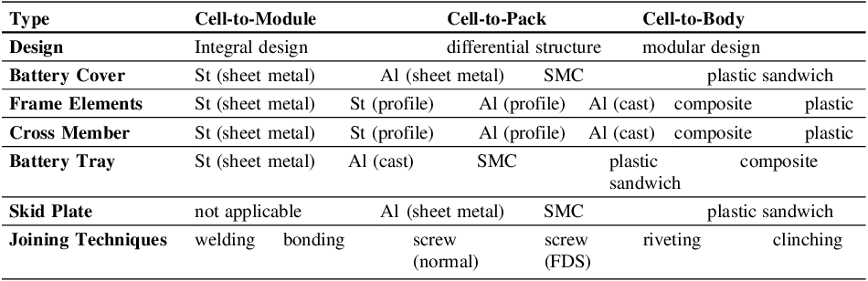
To identify the basic concept directions, a market research and benchmark is performed. It shows that there are three fundamental concepts for the type of the REESS. Volkswagen uses a modular design for the ID.4 (Volkswagen, 2022) (“Cell-to-Module” (Reference Kampker, Heimes, Offermanns, Vienenkötter and RobbenKampker et al., 2023)), Tesla uses body-integrated cells in its Model Y (“Cell-to-Body” (Reference Kampker, Heimes, Offermanns, Vienenkötter and RobbenKampker et al., 2023)), and Teijin Automotive Online (n.d.) demonstrated how cells can be embedded directly into the load-bearing storage structure (“Cell-to-Pack” (Reference Kampker, Heimes, Offermanns, Vienenkötter and RobbenKampker et al., 2023)). The structural parts of the system (Tray, Cover, Frame and Crossmembers) can be from steel sheet metal (Reference HilfrichHilfrich, 2020), aluminum sheet metal, aluminum die cast or aluminum profiles (Volkswagen, 2023). With different materials, also different joining techniques are applicable. To this end, the functions of the housing are reduced to sub-functions, and several partial solutions are developed as rough concept ideas. With the aim of carrying out a technical evaluation in accordance with VDI 2225-3, concept ideas are listed as a morphological box and can be seen in Table 1.
Morphological box of the REESS

*St = Steel, Al = Aluminum, SMC = Sheet Moulding Compound, FDS = Flow Drilling Screw
To carry out the assessment, evaluation criteria are defined and weighted based on CE requirements derived from Design for ReX strategies and REESS requirements. Dismantlability and CO2 reduction receive the highest rating of 4 out of 4 points. Dismantlability is a high priority, as the CE efficiency of the REESS is to be increased through potential Design for Repair, Design for Recycle, and single-type separation. Where possible, components should be replaceable down to the smallest possible unit. CO2 reduction should ensure emissions are minimized through the appropriate selection of materials and processes. The next evaluation criterion, with 3 out of 4 points, is raw material savings. Primary resources (materials and energy sources) should be conserved according to Design for Reduce. Durability and preservation of raw materials are weighted with 2 out of 4 points. Durability is not decisive at this point, as anything that exceeds a service life is considered oversized. Nevertheless, the component should meet the mechanical requirements within its service life. In contrast, the preservation of raw materials should only enable materials to be reused in the next life cycle. The implementation effort of the concept is rated with 1 out of 4 points as a decision criterion when all concepts fulfill their function. However, it is not possible to test all concepts for feasibility within the given framework.
Based on the selected criteria, a plastic-based housing concept (frame, base, and cover) is developed. A cell-to-module approach is chosen for the internal storage system, and detachable connection techniques are to be used wherever possible. Long glass fiber reinforced polypropylene PPGF30 containing post-consumer recyclate (PCR) is used as the plastic material. Due to fiber shortening and property degradation of the PCR, this represents a form of downcycling rather than closed-loop recycling. UD tapes made of glass and carbon fibers with a polypropylene matrix are used for local reinforcement. The carbon and glass fibers are taken into account to achieve the necessary mechanical properties, with the aim of using them as efficiently as possible. Based on the selected load cases, a sandwich structure is a sensible solution, as it can most effectively transfer the expected tensile and compressive stresses to the top and bottom of the components. All components of the structure have a polypropylene matrix, which is intended to improve recyclability due to the purity of the material. In addition, a material bond between the tapes and the matrix is achieved. The sandwich core is to be injection molded, similar to the approach taken by Reference Petersen, Hopmann, Fischer, Emonts, Witte and FoergesPetersen et al. (2024). Five different modifications of compound are available within the project for this purpose. In addition to virgin material, two different quality grades of PCR and PCR contents of 20% and 40% are used. The aim is to enhance the components mechanical performance by incorporating the properties of PCR into finite element analysis models and, at the same time, to assess the environmental impact of using secondary raw materials compared to virgin polymers.
A component library is being developed that contains different design variants of the individual components of the REESS. This library will enable the automated comparison of different component concepts and variations of the components in the assembly during optimization. An optimization algorithm and framework can then be used to swap individual components, compare different assembly concepts, and determine a preferred variant. The individual components are implemented in the SFE Concept 2024_R1 software from Dassault Systèmes. SFE Concept enables parametric modeling, the assembly of components and their connections, including meshing and the assignment of PIDs. An excerpt of the solutions developed for the individual components can be seen in Figure 1. The components differ in their geometric structure, material, and manufacturing process. For example, the inner cross members are implemented either as ribbed injection-molded parts or as pultruded hollow chamber profiles.
To illustrate the methodology and levers for improving environmental impact in detail, the optimization process carried out is tested at the component level for a scaled version of the battery tray, as this is also to be manufactured and is not a purely virtual demonstrator like the parts in the library.
Excerpt of the part library from the REESS

3.3. Structural optimization
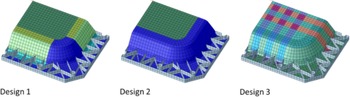
Various concepts for the battery tray are used in the optimization process. The concepts are geometrically identical, but differ in the position and number of UD tapes. The first concept involves full-surface UD layers on the bottom and top of the component. Only the corner areas are omitted for manufacturing reasons. The second concept is simpler to implement in terms of manufacturing technology, with the UD layers only being applied to the flat side of the battery tray. The third concept only involves the use of tape strips that are woven together in a lattice structure. All concept variants as a quarter model can be seen in Figure 2.
Different design variants for the battery tray

The arrangement is implemented in the optimization via different property IDs (PID) in finite element preprocessing. There, the elements are linked to properties such as thickness and material. This means that an area consisting solely of injection-molded material is assigned a different PID than an area in which tape is used. The glass fiber UD tape GF70-PP-UD used has a thickness of 0.2 mm, while the carbon fiber tape TAFNEX CF66-PP-UD has a thickness of 0.15 mm. In the first two concepts, it is always assumed that a 0° layer is followed by a 90° layer to absorb multiaxial loads. In the third concept, this is not necessarily due to the arrangement of the tapes. The component thicknesses are specified by the mold. However, what can be varied at this point is the number and combination of fiber layers. It is assumed that the injection molded core must always be at least 2 mm high to ensure manufacturability and that the layer structures are symmetrical. The number of layers ranges from zero to twelve layers on the top and/or bottom of the injection molded core. The glass fiber layers can be located either on the core or on the top side. For example, a layer structure can consist of six layers of CF-UD tape on the outside and four layers of GF-UD tape on the core. The number and position (core or outside) of the layers apply to all PIDs. This means that, in addition to the component concept and the material for the injection molded core, the number of layers can also be used as design variables.
The bollard test is selected as the decisive load test. LS-DYNA is integrated into the optimization algorithm as the FE solver, and explicit calculations are performed. The component geometry is represented using 3- and 4-corner shell elements, the layer system as PART_COMPOSITE for the sandwich structure and with SHELLS for the pure injection molding compound, whereby layer thicknesses, the material used per layer and the layer orientation are stored directly in this property. MAT215 is used as the material card for the injection-molded core, and MAT58 for the UD tapes, as this also maps the failure of the fiber/matrix combination and evaluates it as a failure signal. The bollard test is simulated as a drop test with a hemispherical impactor (radius of 90 mm), with a impactor mass of 130 kg and initial impact velocity 1.84 m/s, as this substitute load case is to be carried out later in the project to validate the simulation results. The effect occurs in the global z-direction (vertical vehicle axis), the impactor is assumed to be ideally rigid, and the initial velocity is initialized directly via the nodes of the impactor. The model’s positioning simulates the flat contact of the tray over the screw locations on the flange in the global z direction (all flange nodes fixed/applied in z), so that the boundary condition reflects the actual test setup. The contact is defined as AUTOMATIC SINGLE SURFACE, suitable for impact/contact problems with deformable shells and a rigid impactor. The center surface is meshed with an elementary edge length of 5 mm. It is to be expected that local peaks (e.g., very close to contact edges) will occur. For final failure predictions, targeted local refinements should be adjusted to critical areas. The maximum intrusion of the impactor serves as a quality criterion to ensure the structural integrity and intactness of the battery cells. This should therefore be minimized in the optimization.
For the generation of a parameterized equation to be later used in the optimization process for the environmental impact assessment, initially, a base model for the corresponding screening LCA is created. In the foreground system, the injection molding process of the final product is considered, while the background system incorporates all previous material and process inputs, including the production of UD-tapes and the injection molded core. As no information is given on the end-of-life treatment of the product, the modelled system includes a cradle-to-gate perspective and the cut-off method. The base model is constructed in Brightway2 (Reference MutelMutel, 2017), using an Excel spreadsheet, and ecoinvent 3.11 cut-off as the supplementary database (Reference Weidema, Bauer, Hischier, Mutel, Nemecek, Reinhard, Vadenbo and WernetWeidema et al., 2013).
Primary data from a material supplier’s calculation was given for the CF-UD tape, while the other materials and processing steps were modelled with data from the ecoinvent database. No specific information is given on the exact origin of most materials used in this project, but their production is assumed to be located outside of the European region, therefore, average datasets from the rest of the world (RoW) were collected. One exception was made, being recycled polypropylene, for which only a european-based dataset (RER) was available in ecoinvent 3.11. Following the recommendations made by the European Commission, Environmental Footprint v3.1 was chosen as the impact assessment method. Climate change (GWP100), the most important impact category in the corresponding project and one of the most relevant for industrial product optimization, was selected as the impact category.
To align the equation with the degrees of freedom and assumptions defined for the optimization process, a set of four parameters is used for the parameterization of the base model: the absolute volume of the carbon fiber tape VUDCF, the absolute volume of the glass fiber tape VUDGF, the absolute volume of the injection molding compound VPPGF30, and the share of secondary polypropylene in the injection molding compound post-consumer recyclate. Following the choice of parameters, a parameterized equation was extracted manually. For this purpose, firstly, the last process (injection molding) was traced back as far as the model was defined in the Excel spreadsheet, gradually extending the equation. Afterwards, all impacts were calculated as far as possible, until only the above defined parameters remained as variables. The equation was then reduced until the term illustrated in eq. (1). It consists of four parameters and four environmental impacts per volume unit, the latter incorporating both the impact from material production, as well as further processing of the respective materials. As opposed to a complex, Python-based file, the proposed equation can flexibly be further used for product optimization, enabling the inclusion of a product’s possible environmental impact into multicriteria analyses.

In summary, the design variables used are the number of the GF and CF UD tapes, the quality and quantity of the PCR, and the geometric placement of the UD tapes on the battery tray. The most important task of structural optimization is to ensure that the component fulfills its function. In this case, this means that the battery cells must not be damaged under any circumstances to minimize the risk to passengers. Therefore, the objective function is defined as the intrusion of the impactor into the component. This should be as low as possible. The GWP is selected as a further objective function, as it is intended to improve the environmental impact based on the composition and mass of the UD tapes and the injection molding compound. In addition, the mass is included as an objective function. The reason for this is that, due to the different material properties, it cannot be assumed that the mass is also low simply because the GWP is low. As is already known, raw materials should be saved, and a lighter component also has advantages in terms of environmental impact during the use phase. However, due to the recycled content, which affects the GWP, the different quality levels of the injection molding compound also have different material properties, which are incorporated via the material cards. Therefore, two objectives are considered essential, as minimizing the impactor intrusion ensures the structural integrity and the functional safety of the component, while the GWP represents the primary environmental objective in the design phase of the battery tray. Mass is included as an additional objective, as it affects both the use phase and design strategies such as Design for Reduce.
At this point, the optimization procedure will be briefly described. The optimization procedure was implemented in Python, and an interface to SFE Concept and LS-DYNA was integrated. SFE Concept enables automatic adjustment of the geometry, while LS-PrePost is used as a preprocessor. The optimization is formulated as a minimization problem with multiple objectives. A genetic algorithm from the open-source library Pymoo (Reference Blank and DebBlank & Deb, 2020) is used as optimization algorithm.
The interaction of the design variables enables the identification of improved design solutions with respect to GWP, mass, and functional performance, represented by the intrusion. The Pareto-optimal results between the intrusion of the impactor and GWP is shown in Figure 3. All objective functions are normalized for the optimization. To ensure comparability, absolute values of selected Pareto-optimal solutions are additionally reported in Figure 3. This reference design serves as the baseline against which all design modifications and optimization results are evaluated and normalized. The targeted reference design consists of design variant 1, a minimum layer build-up using GF UD tapes and a sandwich core with a PCR content of 20% with high material quality.
The optimization results show that the mass of the battery tray varies by about 10% for all Pareto-optimal solutions, while the GWP varies by up to 250% and the impactor intrusion by up to 55%. Compared to these effects, the influence of mass is therefore limited. Consequently, the following discussion focuses on the trade-off between intrusion and GWP. There are three clusters in the Pareto front, one for each variant of the battery tray and color-coded visible in Figure 3. Design variant 1 contributes only a small number of Pareto-optimal solutions, indicating limited potential for further improvement. In contrast, design variants 2 and 3 dominate the Pareto front and provide a wider range of trade-offs between structural performance and environmental impact. Based on these results, promising designs have to be identified. A quantitative evaluation of selected Pareto-optimal solutions is provided in Figure 3. Compared to the reference design, the design with the lowest global warming potential (Point 2) reduces the GWP by 51% at the expense of an increased impactor intrusion of 13%. In contrast, the design optimized for structural performance (Point 3) reduces intrusion by 32% but increases the GWP by 168%, highlighting the pronounced trade-off between environmental impact and functional performance.
A balanced compromise solution (Point 4) achieves a simultaneous reduction of intrusion by 19% and GWP by 27% relative to the reference design, while maintaining a comparable mass. These results demonstrate that CE-oriented material selection and layer configurations enable significant environmental improvements without disproportionate losses in functional performance.
Pareto front of the intrusion over the GWP

When grouping the Pareto-optimal solutions according to material quality, a clear trend can be identified. High quality materials are predominantly found in the front areas of the Pareto front, while low quality materials are associated with less competitive compromises. No strong dependence on the recycling content (20% vs. 40%) can be observed. The results therefore, suggest that material quality is the dominant factor for the functional and environmental performance of injection-molded components. High quality PCR-based materials, in combination with UDCF and UDGF tapes, can achieve a level of performance comparable to that of virgin material even with a recycled content of 20% and 40%, thus enabling resource conservation without compromising the functionality of the components.
4. Conclusion and outlook
This publication highlights possibilities for reducing the environmental impact of the structural components of a REESS at an early design stage. Promising concepts were first identified at the assembly level of a REESS using a utility analysis derived from Design for ReX strategies and applied within a morphological box. Based on the selected concept, structural optimization at the component level was combined with LCA and structural simulations to further improve the environmental performance of the battery tray while meeting functional requirements. By combining those two methods in the design process, improved concept variants for the battery tray were identified. Low intrusion and low GWP were primarily influenced by the positioning of the UD tapes within the design variants, the combination of GF-UD and CF-UD tapes, and the recyclate content of the injection-molded polymer core. These results can be transferred to the REESS.
Future research will include additional simulations to evaluate how the proposed approaches can improve the environmental impact of the REESS assembly. Further load cases derived from the specifications will be implemented as structural simulations to obtain a more comprehensive representation of the system behavior of the REESS. In addition, the battery tray presented in this study will be manufactured and experimentally tested with an impactor to validate the predicted intrusion results. The LCA of the final concept can also be refined as more detailed data become available beyond the early design phase.
Acknowledgement
This research and development project is funded by the German Federal Ministry for Economic Affairs and Energy (BMWE) within the funding initiative “TTP LB Programm” and implemented by Projektträger Jülich (funding code: 03LB3025A). The author is responsible for the content of this publication.



 Open access

