


Introduction
There has been a recent proliferation of wearable electronics, including health and wellness monitors,Reference Misra, Bozkurt, Calhoun, Jackson, Jur, Lach, Lee, Muth, Oralkan, Öztürk and Trolier-McKinstry1 and sensing systems embedded into clothing.Reference Castano and Flatau2 The vast majority of these devices are battery powered. In some cases, this is not a concern, as regular recharging or replacement is not a major inconvenience. However, in other cases, for example, in the case of 24/7 wellness monitoring, it is critical that the sensing systems not have breaks in operation due to lack of power. Breaks in operation can lead to a situation in which health-critical parameters are not being monitored, which can present safety issues for the user. Furthermore, in most cases, removing the need to replace batteries improves the user experience.
In their seminal study, Starner and ParadisoReference Starner, Paradiso and Piguet3 reviewed human processes that might be tapped for powering wearable or implantable electronics. In the intervening years, there have been many demonstrations of on-body energy harvesters. The most prevalent targeted sources of energy are upper body motion,Reference Pillatsch, Yeatman and Holmes4–Reference Rantz, Xue, Zhang, Gu, Yang and Roundy6 thermal gradients,Reference Stark7–Reference Siddique, Rabari, Mahmud and Van Heyst9 and heel strike (or shoe-integrated harvesters).Reference Paradiso and Starner10–Reference Krupenkin and Taylor12
This article synthesizes recent work on energy harvesting for wearables, focusing on a discussion of system considerations and enabling advances in materials. Given the practical limitations of reviewing such a broad area, this review will focus primarily on three approaches to energy harvesting—thermal energy harvesting, mechanical-inertial mass-based harvesters, and clothing integrated harvesters. Both system-level approaches and the relevant materials considerations are discussed.
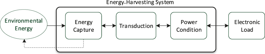
For all body-worn harvesting approaches, the problem of energy harvesting can be broken down into three pieces—capturing energy from the environment, transducing that energy to electricity, and conditioning the electrical energy for use. (Note, some systems also contain an energy-storage function such as a rechargeable battery or a supercapacitor.) This process is illustrated in Figure 1. Thermal energy harvesting utilizes the temperature difference between the human body and the ambient. The “capture mechanism” would be a heat spreader that touches the skin and a heatsink in contact with the ambient. The heat spreader and sink direct heat flow through the thermoelectric (TE) elements and should be designed to ensure optimal temperature drop across the TE elements, which are the transducing material. This article discusses the design of capture mechanisms and transducer materials, while devoting minimal attention to conditioning electronics.
Energy-harvester system diagram.
Thermal energy harvesting
System considerations
The transduction material for thermal energy harvesting for on-body applications is often a TE material. TE materials function by converting a temperature difference into an electrical potential. The primary system consideration for thermal energy harvesting is to maximize the temperature drop across the TE elements.
A thermal energy-harvesting system can be modeled simply by a thermal-resistive network as in Figure 2. If the thermal resistance (reciprocal of thermal conductance) across the skin and substrate in contact with the skin or the thermal resistance between the heatsink and the air is high relative to the thermal resistance of the TE elements, then most of the temperature drop will occur across those thermal resistances and not generate any power. While the model in Figure 2 is simplified, this basic insight is equally true for more sophisticated models. Suarez et al.Reference Suarez, Nozariasbmarz, Vashaee and Öztürk8 published a thorough analysis of the design of TE energy-harvesting systems for wearable devices and showed that most of the temperature difference between the body’s core and the ambient is lost across the skin, substrate, and heatsink rather than the TE elements. Therefore, minimizing the thermal resistances associated with these three elements can have as large an effect on system performance as engineering the TE material itself.
(a) Drawing illustrating a body-worn thermoelectric (TE) energy harvester. (b) Equivalent resistive network, where T C and T H are the temperatures of the air and body, respectively, and R C, R TE, and R H are the thermal resistances of the heatsink, TE elements, and heat spreader in contact with the skin, respectively. R PAR is the thermal resistance of the material (usually air) in between the TE elements. The blue and pink TE elements denote n- and p-type materials, respectively.
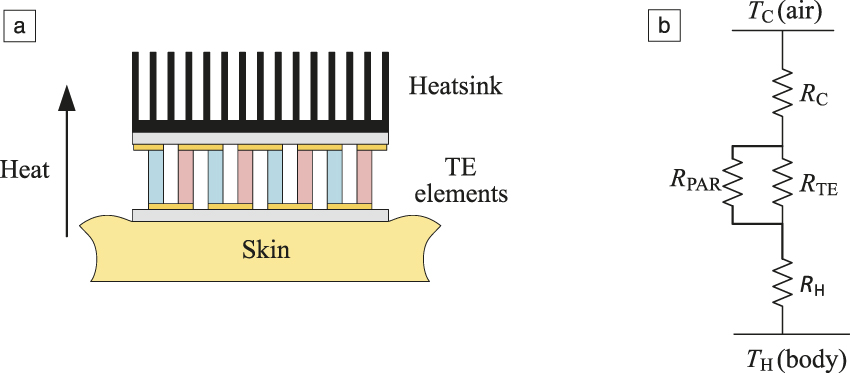
Additionally, the thermal resistance of parallel paths to heat flow, R PAR in Figure 2, must be maximized or else all the heat will flow around the TE elements rather than through them. This parallel path represents heat flowing in the space between the TE elements. If this space is air, R PAR will be high, and the associated losses will be small. However, if this space is filled with an elastomer, for example, as might be appropriate for flexible systems, the parallel heat loss can be significant.Reference Suarez, Nozariasbmarz, Vashaee and Öztürk8
Thermal energy-harvesting systems targeting wearable applications are prevalent in the scholarly literature in both rigidReference Stark7,Reference Leonov and Vullers13–Reference Leonov and Vullers15 and flexibleReference Misra, Bozkurt, Calhoun, Jackson, Jur, Lach, Lee, Muth, Oralkan, Öztürk and Trolier-McKinstry1,Reference Siddique, Rabari, Mahmud and Van Heyst9,Reference Kim, Kim, Lee, Kim and Kim16–Reference Wan, Tian, Azizi, Huang, Wei, Sasai, Wasusate, Ishida and Koumoto18 form factors. Bahk et al.Reference Bahk, Fang, Yazawa and Shakouri19 have reviewed TE energy harvesters for wearable applications with a focus on flexible materials. Power densities of the many reviewed publications vary widely, but are all less than 100 μW/cm2. To achieve even tens of μW/cm2, bulky rigid heatsinks are necessary. Suarez et al.Reference Suarez, Nozariasbmarz, Vashaee and Öztürk8 conducted a similar study and demonstrated power densities of 10–100 μW/cm2, depending on air velocity with a rigid 6 cm2 heat spreader. In order to overcome the need for large and rigid heatsinks, some researchers are investigating thin and flexible nanostructured heatsinks.Reference Misra, Bozkurt, Calhoun, Jackson, Jur, Lach, Lee, Muth, Oralkan, Öztürk and Trolier-McKinstry1 Such systems may be able to generate power on the order of hundreds of μW/cm2 in flexible systems.
Material considerations
The efficiency of a TE device depends on the material’s figure of merit (FOM):  $ZT = {{S^2 {\rm{\sigma }}} \over {\rm{\kappa }}}$,
where S is the Seebeck coefficient,  $\sigma$ is the electrical conductivity, and ${\rm{\kappa }}$ is the thermal conductivity. Body-worn TE devices should have peak efficiencies near room temperature, with high and matched ZT for both n-type and p-type elements (see Figure 2). Given the high input and output thermal resistances of wearable devices, reducing the thermal conductivity of the TE elements has a much larger effect on output power than improving the material FOM (ZT). In practice, lower ${\rm{\kappa }}$ is achieved by reducing phonon contributions to thermal conductivity by developing strong scattering from grain boundaries, phase boundaries, and incorporated glassy regions.Reference Hyland, Hunter, Liu, Veety and Vashaee20,Reference Poudel, Hao, Ma, Lan, Minnich, Yu, Yan, Wang, Muto, Vashaee, Chen, Liu, Dresselhaus, Chen and Ren21 Microstructure on the nanometer-length scale is most effective. Such fine-scale microstructures can be achieved via a number of routes, including microwave processing and incorporation of second phases.
Although in principle, fine-grained microstructures should produce high fracture toughness, in many cases, cracks and porosity complicate fabrication of the tall, thin legs helpful to maintaining a useful temperature difference between the skin and ambient without excessively clunky heatsinks. This drives work on improving processing of the TEs.
A comparison of TE materials reveals that Bi2Te3-based materials are well suited for on-body harvesting, as their ZT value peaks near room temperature.Reference Poudel, Hao, Ma, Lan, Minnich, Yu, Yan, Wang, Muto, Vashaee, Chen, Liu, Dresselhaus, Chen and Ren21 Significant progress has been made in developing nanostructured p-type TEs with high performance. However, there are fundamental challenges in making matching n-type TEs. First, Bi2Te3 suffers from lower number of electron pockets near the conduction-band edge compared with the number of hole pockets in the p-type alloy, reducing the Seebeck coefficient, and second, there is more anisotropy in the TE properties of n-type Bi2Te3 than in the p-type material; thus, random polycrystals degrade the values for S 2σ.Reference Hyland, Hunter, Liu, Veety and Vashaee20,Reference Poudel, Hao, Ma, Lan, Minnich, Yu, Yan, Wang, Muto, Vashaee, Chen, Liu, Dresselhaus, Chen and Ren21 As S 2σ drops more rapidly than κ in n-type Bi2Te3, the result is a net loss in efficiency.
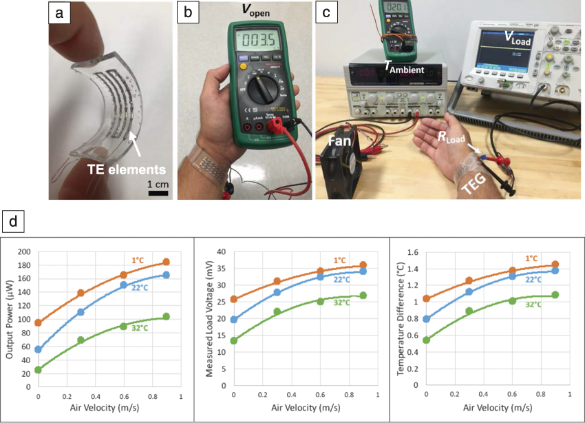
Additional considerations for wearable energy harvesters include flexibility, good thermal contact to both skin and air, and the need to obtain an output voltage that is high enough to enable efficient boost conversion for charging the battery. In particular, either the TE or its package should be flexible to maintain intimate thermal contact with the skin, such that the hot junction temperature can be maintained, preferably without imposing an uncomfortable mechanical pressure or a propensity for sweating underneath the TE. Likewise, good thermal contact with air and a finite airflow over the device are helpful in increasing the generated power, as seen in Figure 3.Reference Suarez, Parekh, Ladd, Vashaee, Dickey and Öztürk22,Reference Sargolzaeiaval, Neumann, Suarez, Ramesh, Parekh, Vashaee, Dickey and Öztürk23 The figure shows a flexible device in which the TE elements are embedded in a polymer package, using liquid-metal contacts. Figure 3d demonstrates that the measured (and modeled) output voltage, power, and temperature drop across the TE can increase as the air velocity over the TE generator rises.
(a) Flexible thermoelectric energy generator (TEG) using liquid-metal contacts on thermoelectric (TE) elements, (b) measurement of open-circuit voltage on-body, (c) experimental setup for measurements as a function of airflow, and (d) measured voltage, power, and temperature drop across the TE elements for a body-worn TE harvester. From (d), it is apparent that as the air velocity over the TE increases, it becomes easier to maintain a temperature gradient (ΔT) over the TE elements. As a result, the measured voltage over the load and power level rises. Reprinted with permission from Reference Reference Sargolzaeiaval, Neumann, Suarez, Ramesh, Parekh, Vashaee, Dickey and Öztürk23. © 2017 ICT. Note: V Load, voltage on the load; T Ambient, ambient temperature; V open, open-circuit voltage; R Load, load resistance. (a–c) Reproduced with permission from Reference Reference Suarez, Parekh, Ladd, Vashaee, Dickey and Öztürk22. © 2017 Elsevier.
Finally, the efficiencies of many DC-DC boost converters drop off substantially at voltages below 20–50 mV. As a result, it is important to be able to use enough legs that the voltages can add to high enough levels, without having so many that the legs provide a thermal short-circuit between the body and the air.
It should be noted that for normalizing performance of TE materials and devices, the convention is to divide by the active area of the TE module; this is often much smaller than the thermal collection area.
Inertial energy harvesting
System considerations
There are generally two approaches to harvesting energy from the mechanical motion of the human body. In one approach, forces generated by contact and joint rotation are directly coupled to an electromechanical transducer. This approach will be covered in the section on “Mechanical clothing-integrated harvesters.” The other approach is to use human motion to excite another inertial mass. The kinetic energy of this inertial mass is then converted to electrical energy by means of a transducer.
The first goal of an inertial energy harvester is to maximize the amount of energy transferred from the environment to an inertial mass. This is the energy capture mechanism. Vibration energy harvesters typically maximize energy captured through the use of resonant linear mechanical oscillators.Reference El-hami, Glynne-Jones, White, Hill, Beeby, Brown and Ross24–Reference Roundy and Wright26 However, human motion is more difficult to capture than typical vibrations because it is slow, often nonperiodic, and occurs along all three linear and rotational axes. Several basic mechanical architectures for the energy capture system have been proposed, including eccentrically weighted rotors withReference Yeatman27 and without a restoring spring,Reference Pillatsch, Yeatman and Holmes4,Reference Hayakawa28–Reference Lockhart, Janphuang, Briand and de Rooij34 linear slides or oscillators,Reference Renaud, Fiorini, van Schaijk and van Hoof5,Reference Halim and Park35–Reference Geisler, Boisseau, Perez, Ait-Ali and Perraud39 and a spherical magnet rolling inside a spherical cavity.Reference Rao, Cheng and Arnold40,Reference Rao, McEachern and Arnold41 (See Figure 4.) Each design has its advantages, but the eccentric rotor seems to be the most prevalent and has the advantage that it can be excited by linear or rotational motion about any axis and it responds well to slow motions.
Wearable inertial energy-harvester architectures: (a) eccentric rotor,Reference Xue, Yeo, Trolier-McKinstry and Roundy32 (b) linear slide,Reference Geisler, Boisseau, Perez, Ait-Ali and Perraud39 and (c) spherical magnet in spherical cavity.Reference Rao, McEachern and Arnold41 Note: PZT, lead zirconate titanate, Pb(Zr0.52Ti0.48)O3.

The second goal of an inertial energy harvester is to transduce the kinetic energy of the inertial mass into electrical energy. The design of the capture mechanism does not necessarily determine the type of transducer. For example, eccentric rotor-based harvesters have been demonstrated with piezoelectric,Reference Pillatsch, Yeatman and Holmes4,Reference Xue, Yeo, Trolier-McKinstry and Roundy32,Reference Lockhart, Janphuang, Briand and de Rooij34 electromagnetic,Reference Hayakawa28–Reference Romero, Neuman and Warrington30,Reference Halim, Rantz, Zhang, Gu, Yang and Roundy33 and electret-based electrostaticReference Nakano, Komori, Hattori and Suzuki31 transducers. The function of the transducer is to convert kinetic energy to electrical energy at the right rate. A transducer with a higher level of coupling (e.g., higher piezoelectric FOM, higher flux density magnets) will convert energy at a higher rate. From the perspective of a purely mechanical system, this higher rate of energy transfer appears as extra damping (or frictional loss). It is important to point out that there is an optimal rate of energy transduction or electromechanical coupling. If it is too high, the inertial mass can become overly damped and not move much. If the coupling is too low, not enough of the energy captured by the mass gets converted to electricity. It is far more common for the transducer to provide too little coupling (this is called an undercoupled system), and thus, material improvements to the transducer usually (although not always) have the effect of improving generated power by increasing the level of electromechanical coupling.
Demonstrated power densities for wearable inertial energy harvesters range from single-digit μW/cm3 Reference Pillatsch, Yeatman and Holmes4,Reference Nakano, Komori, Hattori and Suzuki31 to 150–180 μW/cm3.Reference Haroun, Yamada and Warisawa37 Mitcheson et al.Reference Mitcheson, Yeatman, Rao, Holmes and Green42 developed, in an analytical study, a theoretical upper bound on power density of 1 mW/cm3 under an assumed excitation of 1G (G = gravitational acceleration = 9.81 m/s2) at 1 Hz. These conditions would correspond to vigorous walking. They assumed a linear slide architecture with generous inertial properties. Xue et al.Reference Xue, Ma, Rahn and Roundy43 followed a similar approach and found an upper bound of hundreds of microwatts under a walking excitation for a wrist-mounted device. While these upper bounds do not necessarily apply to all architectures, demonstrated devices are well below them, a fact that indicates significant room for improvement through both innovative system design and improvements in transducer materials and technologies.
As a final note, readers must be careful about comparing the power output of one type of device to another, and demonstrated power outputs to theoretical upper-bound estimates. The excitation conditions for reported power generated vary widely from slow walkingReference Xue, Ma, Rahn and Roundy43 to running,Reference Pillatsch, Yeatman and Holmes4 to shaking with one’s hand,Reference Halim and Park35 to 17 G vibration excitations.Reference Haroun, Yamada and Warisawa37 In the authors’ opinion, a representative standard test sorely needs to be developed for accurate and relevant benchmarking of wearable energy harvesters.
Material considerations—Piezoelectric
In choosing piezoelectric materials for on-body harvesting, the mechanical excitation mode, the product of the piezoelectric charge and voltage coefficients, achievable strain, and piezoelectric volume all affect the power level attained. It is also imperative that the material have a low dielectric loss at the frequencies for harvesting, such that all of the available power can be extracted via the circuit, rather than dropping across the material.
Priya et al.Reference Kim, Tadesse, Priya, Priya and Inman44 describe how energy-harvesting FOM scales with  ${d_{33}} \times {g_{33}} = {{d_{33}^2} \over \varepsilon_{33} },$ where d 33 is the piezoelectric charge coefficient, g 33 the piezoelectric voltage coefficient, and ε33 the relative permittivity, written in matrix notation for bulk materials compressed parallel to the polar axis. For thin films, where the strain coefficients are typically better known than the stress coefficients, the analogous term is ${e_{31,f}} \times {h_{31,f}} = {{e_{31,f}^2} \over {{\varepsilon _{33}}}}$ for a thin filmReference Yeager and Trolier-McKinstry45 with top and bottom electrodes in a flexural harvester. Again, it is essential that the device generate voltages large enough to be efficiently converted by the rectification electronics, which is easier for voltages >0.25 V. This is trivial in the case of bulk ceramics (where the opposite problem of inconveniently high voltages is regularly encountered), but is more challenging in thin films. As an alternative to top and bottom electrodes, higher voltages can often be achieved using interdigitated top electrodes on the film, although at the expense of the current.Reference Jeon, Sood, Jeong and Kim46
Two key approaches have been taken to increasing the FOM. Increasing e 31,f has been achieved without rapidly increasing relative permittivity in modified AlN compounds such as Al1–xScxN. Here, the low base permittivity counterbalances the comparatively low piezoelectric responses. In perovskite ferroelectrics, the largest piezoelectric responses are achieved in [001]-oriented domain engineered crystals, oriented ceramics, or thin films. However, these compounds typically have large relative permittivities. Thus, to increase the FOM for energy harvesting, the permittivity can be decreased by applying residual stresses that force the polarization out-of-plane,Reference Yeager, Yoshitaka, Oshima, Funakubo and Trolier-McKinstry47 strongly imprinting the film to produce a strong internal DC bias,Reference Trolier-McKinstry, Griggio, Yaeger, Jousse, Zhao, Bharadwaja, Jackson, Jesse, Kalinin and Wasa48 or incorporating porosity. A comparison of FOMs for various thin-film materials is shown in Figure 5.Reference Yeager, Yoshitaka, Oshima, Funakubo and Trolier-McKinstry47–Reference Ujimoto, Yoshimura, Ashida and Fujimura55
Comparison of piezoelectric coefficients and energy-harvesting figures of merit (FOMs) for a series of piezoelectric films. To date, the highest FOMs for kinetic energy harvesting have been achieved in doped AlN compounds and c-domain perovskite films. Note:  ${e_{31,f}}$, piezoelectric charge coefficient for thin film.Reference Yeager, Yoshitaka, Oshima, Funakubo and Trolier-McKinstry47–Reference Ujimoto, Yoshimura, Ashida and Fujimura55

Material considerations—Triboelectric
As an alternative to piezoelectric energy harvesting, electromagnetic, electrostatic, and triboelectric modalities are also possible. Electromagnetic devices are of particular value when the system size is large (e.g., >1 cm3).Reference Cook-Chennault, Thambi and Sastry56 While electrostatic generators can readily be miniaturized, they require a priming charge from a power supply; therefore, they may not always be suited to wearable applications.
Triboelectric devices have recently been reported to be of interest for body harvesting. Fundamentally, this mechanism relies on friction to generate opposite electric charges on different surfaces. If these charges can be collected on electrodes, high instantaneous powers can be achieved by this mechanism.Reference Fan, Tian and Lin Wang57 It is less clear that the average power levels will be adequate for many applications. From a materials perspective, the key attributes for a wearable triboelectric harvester are a comparatively rough surface to maximize the friction, abrasion-resistance to prevent wear, the ability to produce large-area parts to facilitate integration into garments, and some level of stretchability or flexibility for comfort.Reference Cheng, Lu, Hoe Chan, Wang, Cao, Sun and Wei Ho58 Many papers report on the use of abundant fibers such as cellulose or silk as key constituents of a wearable harvester.
Mechanical clothing-integrated harvesters
System considerations
The primary distinction between inertial harvesters and clothing-integrated harvesters for the purposes of this article is that clothing-integrated harvesters get their power from direct interaction with the body, rather than by coupling the energy to an intermediate inertial mass. This energy could come from joint bending,Reference Yang and Yun59–Reference Lee, Chen, Wang, Cha, Park, Kim, Chou and Wang61 direct force such as tapping or pushing on the clothing,Reference Almusallam, Luo, Komolafe, Yang, Robinson, Torah and Beeby62 friction between the relative motion of two components of clothing,Reference Kwak, Kim, Seung, Kim, Hinchet and Kim63–Reference Seung, Gupta, Lee, Shin, Lee, Kim, Kim, Lin, Kim and Kim65 or chest expansion.Reference Padasdao, Shahhaidar, Stickley and Boric-Lubecke66
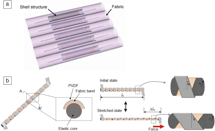
Much work has focused on developing flexible and stretchable transducer materialsReference Kwak, Kim, Seung, Kim, Hinchet and Kim63,Reference Pu, Li, Song, Du, Zhao, Jiang, Cao, Hu and Wang64,Reference Yun and Yun67–Reference Kim and Yun70 and integrating transducers into clothing.Reference Seung, Gupta, Lee, Shin, Lee, Kim, Kim, Lin, Kim and Kim65,Reference Wu, Bai, Yuan, Qin, Wang and Jing69 Material issues are covered in more detail in the following section. Here, we simply note that transducers are generally piezoelectric,Reference Almusallam, Luo, Komolafe, Yang, Robinson, Torah and Beeby62,Reference Wu, Bai, Yuan, Qin, Wang and Jing69,Reference Kim and Yun70 electrostatic,Reference Eun, Kwon, Kim, Yoo, Sim, Ko, Cho and Kim68 or triboelectric.Reference Kwak, Kim, Seung, Kim, Hinchet and Kim63–Reference Seung, Gupta, Lee, Shin, Lee, Kim, Kim, Lin, Kim and Kim65 There are fewer papers demonstrating clothing-integrated harvesting systems. Yang and YunReference Yang and Yun59 demonstrated a flexible semitubular piezoelectric shell structure-based harvester that can be put into a finger or elbow joint harvester and that yields 2.18 mW/cm2 from being cyclically bent by 80° at 3.3 Hz (see Figure 6). Yun et al.Reference Kim and Yun70 demonstrated a stretchable device incorporating piezoelectric helices wrapped around a stretchable core (see Figure 6). This device produced 0.3 mW/cm3 from applying a cyclical strain of 60% at 4 Hz. Padasdao et al.Reference Padasdao, Shahhaidar, Stickley and Boric-Lubecke66 demonstrated an average power of 0.072 mW from a chest band that, under expansion from breathing while walking, turns a DC brushed motor used as a generator. While power densities of 2.18 mW/cm2 and 0.3 mW/cm3 seem promising, the excitations do not seem to correlate to any normal human motion.
(a) Piezoelectric shell structure that can generate power from being placed in fabric on the elbow or finger. Reprinted with permission from Reference Reference Yang and Yun59. © 2012 Elsevier. (b) Wearable harvester incorporating helical piezoelectric strips around a stretchable core.Reference Kim and Yun70 When the device is stretched, the helical piezoelectric structure experiences a torsional and longitudinal tensile stress, which produces an electrical potential. Note: PVDF, poly(vinylidene fluoride), 110-μm thick; l 0, initial harvester length; Δl H, change in harvester length; θ0, winding angle of the PVDF strap; θ, deflected angle of the PVDF strap after stretching; r 0, initial core radius; r, final core radius.
Starner and Paradiso,Reference Starner, Paradiso and Piguet3 and Riemer and ShapiroReference Riemer and Shapiro71 both studied the mechanics of body motion to estimate how much power the body exerts during different motions. The results relevant to clothing integrated harvesters from these studies are summarized in Table I.
Summary of power consumed by human body during various actions.
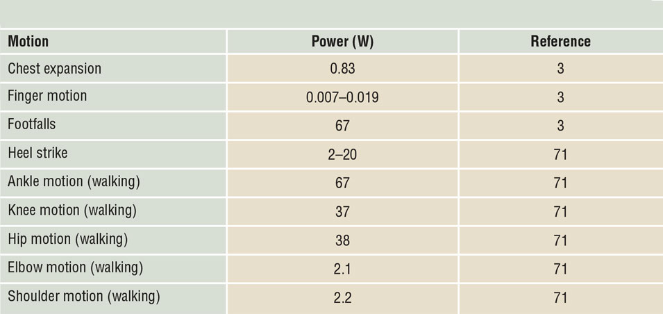
The amount of power available via knee bending and ankle motion, for example, is quite large—tens of watts. However, as previously summarized, reported power outputs are far below what is possible, indicating much space for innovation. The forces available from joint bending can be large, however, coupling to those forces to generate power generally results in very tight-fitting clothing that may not be comfortable and may feel restrictive to the user. Chest expansion is a good example. Because we are always breathing, accessing the power available from chest expansion could be a reliable way to power smart clothing. However, the extra compression around the chest required to couple the transducer (i.e., flexible piezoelectric material,Reference Shahhaidar, Padasdao, Romine, Stickley and Boric-Lubecke72 or a small motorReference Padasdao, Shahhaidar, Stickley and Boric-Lubecke66) to chest expansion can result in an unacceptably restrictive garment or chest band. Some motions are energetic, such as hip motion, but difficult to couple because of the small changes in joint angle. So, while there is a lot of potential power that could be generated from clothing, doing so in a comfortable and practical way has not been well demonstrated. Finally, system-level challenges include the difficulty of integrating electromechanical transducers with fabric and finding transducer materials with the required level of stretchiness to ensure user comfort.
Material considerations
Several approaches can be taken in creating flexible or stretchable harvesters. As previously described, there is an extensive research effort now on integrating triboelectricity into large-scale garments through means such as weaving functional fibersReference Song, Zhang, Guo, Chen, Su, Chen, Cheng and Zhang73 or spray-coating preexisting fabrics.Reference Liu, Li, Che, Chen, Wang and Zhou74 This provides the inherent flexibility associated with textiles.
Piezoelectric polymers are lightweight, tough, and available in large-area formats, and can be formed into complex shapes.Reference Davis and Wong75 Of these, commercially available ones include polyvinylidene fluoride (PVDF) and PVDF-trifluoroethylene copolymers. Conventional bimorph structures have been made using PVDF as the active layer of a bending-based harvester that could readily be integrated into clothing.Reference Won, Sheldon, Mostovych, Kwak, Chang, Ahn, Kingon, Kim, Kim, Won, Sheldon, Mostovych and Kwak76 PVDF typically tolerates much higher strain levels (up to 3%) than ceramic materials such as those shown in Figure 5, thus allowing higher powers to be extracted even though the energy-harvesting FOM is smaller.
Alternative approaches to achieving flexible piezoelectric harvesters include use of flexible substrates such as metal foils,Reference Yeo and Trolier-McKinstry77 or transferring piezoelectric layers onto polymers.Reference Liu, Wallace, Trolier-McKinstry and Jackson78 The latter can be accomplished through the use of a sacrificial layer underneath the piezoelectric layer.Reference Qi, Jafferis, Lyons, Lee, Ahmad and McAlpine79 MgO, Si, and ZnO have all been utilized for the sacrificial layer. The latter two, in particular, have etchants that are selective with respect to a number of high FOM energy-harvesting materials, facilitating transfer to the flexible substrate with a minimum of damage.
Conclusions
On-body energy harvesting can take many forms. This article has sought to discuss system and materials considerations for three classes of on-body energy harvesters—thermal energy harvesters, inertial energy harvesters, and clothing integrated (or flexible) energy harvesters. The article also briefly reviewed the state of the art for each class of energy harvester. In all cases, there has been a large amount of activity recently in the research community and significant progress. However, the performance of current system demonstrations is well below what is theoretically possible. Thus, there is significant space, and need, for innovation at both the system and materials levels.
Acknowledgments
The authors gratefully acknowledge the support of the National Science Foundation (NSF) ASSIST Nanosystems ERC under Award No. EEC-1160483. S.T.M. also acknowledges NSF Award No. CNS-1646399.

Shad Roundy joined The University of Utah in 2012 as a faculty member in the Department of Mechanical Engineering. He received his PhD degree in mechanical engineering from the University of California, Berkeley, in 2003. He was a senior lecturer at the Australian National University for two years. He worked with startup companies for several years prior to joining The University of Utah. He is the recipient of the DOE Integrated Manufacturing Fellowship, the Intel Noyce Fellowship, and was named by the Massachusetts Institute of Technology’s Technology Review as one of the world’s top 100 young innovators for 2004. His current research interests include harvesting energy for wireless sensors, particularly from vibrations, acoustics, and human motion. Roundy can be reached by phone at 801-581-4304 or by email at shad.roundy@utah.edu.

Susan Trolier-McKinstry is the Steward S. Flaschen Professor of Ceramic Science and Engineering and professor of electrical engineering at The Pennsylvania State University (Penn State), where she also serves as the director of the Nanofabrication Facility. She obtained her BS, MS, and PhD degrees in ceramic science and engineering, all from Penn State, and joined the faculty there after graduation. She is a fellow of MRS, IEEE, and The American Ceramic Society, and is an academician of the World Academy of Ceramics. She was president of the Materials Research Society in 2017. Her current research interests include thin films for dielectric and piezoelectric applications. Trolier-McKinstry can be reached by phone at 814-863-8348 or by email at stmckinstry@psu.edu.


