





Nomenclature
- MRO
-
maintenance repair and overhaul
- UWB
-
ultra-wideband
- MoCap
-
motion-capture
- DOF
-
degrees of freedom
- PoE
-
Power over Ethernet
- EKF
-
extended Kalman filter
- ToA
-
time-of-arrival
- TDoA
-
time-difference-of-arrival
- IMU
-
inertial measurement unit
- FOD
-
foreign object debris
- DXF
-
Drawing eXchange Format
- OEM
-
original equipment manufacturer
- NIC
-
network interface cards
- MTU
-
maximum transmission unit
- LpBinary
-
linear-programming of binary type
- CBC MILP
-
COIN-OR branch-and-cut – mixed-integer linear programming
- SLAM
-
simultaneous localisation and mapping
- MILP
-
mixed-integer linear programming
- ROS
-
robot operating system
- GigE
-
gigabit ethernet
- LiDAR
-
light detection and ranging
- USB
-
universal serial bus
- CCTV
-
closed-circuit television
- SVG
-
Scalable Vector Graphics
- SPF
-
small form-factor pluggable
- UTP
-
unshielded twisted pair
- Cat6
-
category 6
- TOF
-
time of flight
- RTT
-
round-trip time
- NDT
-
nondestructive testing
- GSD
-
ground sampling distance
- FoV
-
field of view
- TRL
-
technology readiness level
- CMC
-
ceiling-mounted camera
- RF
-
radio frequency
1. Introduction
Accurate localisation is fundamental to enabling autonomous robotic inspection in MRO hangars, where metallic structures, extensive multipath effects and strict operational constraints define a unique and challenging environment [Reference Plastropoulos, Zolotas and Avdelidis1]. Existing localisation technologies, including infrared MoCap, UWB, and camera-based systems or on-board simultaneous localisation and mapping (SLAM) approaches, offer different trade-offs in terms of achievable accuracy, infrastructure complexity, cost and robustness to occlusion and interference [Reference Masiero2]. Sensor fusion frameworks that combine vision, inertial and UWB data can improve robustness and deliver cost–accuracy trade-offs, as demonstrated in large-scale warehouse deployments. However, their performance and economic viability remain highly dependent on environment-specific factors [Reference Van Gerwen3]. In the context of this research, monitoring is defined as the real-time tracking of assets such as ground support equipment, tool trolleys and personnel within the bay. Localisation focusses on determining the real-time position and orientation of ground and aerial platforms operating in proximity to the aircraft. Finally, artefact detection is addressed, with an exploration of how sensing can facilitate the identification of surface defects and other critical features on the airframe. The framing of these macroscopic and microscopic needs together sets the stage for the optimisation framework, comparative experiments and cost analyses developed in the remainder of the paper.
Despite technical advances, a notable lack of comprehensive, real-world techno-economic analyses remains, specifically focused on aircraft hangar deployments. The available literature provides only partial benchmarking or component-level comparisons for individual or hybrid localisation modalities [Reference Park and Cho4, Reference Pugliese, Konrad and Abel5], with little empirical evidence on their robustness to the full spectrum of hangar-specific challenges such as dynamic occlusion, specular reflections and integration with existing maintenance workflows. To date, no studies have presented a holistic side-by-side evaluation of MoCap, UWB and vision-based solutions in an operational aircraft hangar context. This persistent gap underscores an urgent need for domain-specific comparative studies, including rigorous assessments of cost, accuracy and integration, to inform the reliable and scalable deployment of robotic inspection systems in aviation environments. The economic impact of daily maintenance practices has begun to be quantified by recent hangar-focused studies; for instance, significant rework costs in narrow-body bays can be avoided by improving technicians’ awareness of composite repair, as demonstrated by Jong et al. [Reference Jong6]. Across the timeline, Moenck et al. [Reference Moenck7] outline how the forthcoming Industry 5.0 automation could reshape the trade-offs of labour hours and logistics on large MRO campuses. At the same time, the classic aerodynamic analysis of the enclosed engine test hangars by Wallis and Ruglen still provides a valuable historical baseline for energy throughput economics [Reference Wallis and Ruglen8].
In summary, this study offers five significant contributions: (i) it presents the inaugural techno-economic analysis that evaluates MoCap, UWB and CMC systems in parallel for full-scale aircraft hangars; (ii) it introduces a two-stage optimisation framework for camera selection and placement that combines market-driven camera-lens selection with a mixed-integer linear programming (MILP)-based set-cover placement, resulting in the minimal number of cameras needed; (iii) it supplies quantified design-to-cost case studies converting three typical MRO tasks into specific bills of materials and cost estimates; (iv) determines the optimal balance for defect-detection accuracy, illustrating how ceiling cameras and drone close-ups converge at various defect sizes; and (v) provides the first cost/accuracy comparison between camera localisation and commercial UWB/MoCap systems for a conventional 40 × 50 m bay. Collectively, these contributions deliver an actionable and comprehensive methodology for MRO decision-makers to select, size and cost localisation and inspection systems within large hangars. The framework demonstrated in the case studies is applied to a rectangular single bay hangar measuring 40 × 50 m for narrowbody aircraft. The optimisation and coverage mapping processes are fully parametric in terms of bay width, length and ceiling height.
Inspired by the aviation industry’s shift towards Industry 5.0, which sees mobile robots and AI-based decision support systems taking on routine maintenance duties, the hangar should transition from a passive shelter to a dynamic sensing platform. The end goal is a ceiling infrastructure dense enough to localise robots, track assets and even surface defects in real-time, but lean enough to be economically retrofitted into legacy bays. Against this backdrop, the remainder of the paper is organised as follows. Section 2 reviews the state-of-the-art in MoCap, UWB and CMC systems, clarifying their respective accuracy, cost and integration trade-offs. Section 3 introduces a two-stage optimisation framework for camera selection and placement that first selects a market-ready camera–lens pair and then solves a set-cover problem to minimise hardware while meeting resolution targets. Section 4 translates those algorithms into three design-to-cost frameworks: robot localisation, asset tracking and defect detection, each with a detailed bill of materials for practitioner guidance. It also presents MoCap and UWB implementation options for benchmarking.
2. Digital Sending Options for the Smart Hangar
The hangar is a space where multiple maintenance tasks from various technical teams are performed simultaneously. Effective coordination, spatial awareness and asset management are crucial to increase productivity and minimise mistakes. In addition, precise localisation is crucial for evaluating applications involving robotics. Therefore, it is no surprise that when Airbus first introduced the concept of the Hangar of the Future, the localisation system was part of the suggested enabling technologies [Reference Plastropoulos9]. For this concept, the UWB system was chosen. The choice was reasonable since it provides a balance between cost and accuracy. Ubisense has publicly shared two related experiments. In the first, the system provides localisation data for a drone that performs aircraft inspection [10]. In the second study [11], the focus was on asset management and digital twins. An alternative method, which is not widely adopted in hangars, involves utilising a MoCap system. Although this provides greater accuracy, it is more expensive and requires a line of sight with a minimum of two cameras [Reference Aurand, Dufour and Marras12]. Yet another technique, still in the research stage but showing significant potential, is to explore the usage of a camera-based system enhanced with deep learning models capable of executing various tasks [Reference Konrad13, Reference Huang14]. The subsequent section outlines each approach by highlighting its fundamental functions, characteristics and constraints, along with its standard architecture. For the camera-based system, three candidate architectures are illustrated on the basis of specific target scenarios.
In this section, background is grouped by sensing family (MoCap, UWB, CMC systems), followed by use-case (localisation, monitoring, defect detection), with dimensional assumptions kept adjacent to each use-case for easy cross-reference to Section 3 (methods) and Section 4 (blueprints).
2.1. Optical motion-capture systems
MoCap systems are technologies that estimate the 3D positions and orientations (six degrees of freedom (DOF) poses) of tracked objects using camera-based tracking of reflective or active markers. These systems operate by triangulating marker positions from multiple synchronised camera views and are widely used in fields such as robotics, biomechanics and animation. Commercial systems such as Qualisys, Vicon and OptiTrack use high-speed infrared cameras configured around a workspace to track marker-equipped objects with submillimeter precision. For robotic localisation tasks, especially in indoor settings, MoCap systems provide highly accurate pose data that can be integrated into robotic frameworks, such as those based on the robot operating system (ROS), enabling real-time control, mapping or trajectory following.
The MoCap systems use multiple infrared cameras and reflective markers to determine 3D positions in real-time. Reflective markers are small spheres (often coated with retro-reflective material) placed on the object of interest. The reflective coating ensures that the markers appear as bright spots in the camera images whenever IR light is reflected from them. For robot localisation, typically, multiple markers are affixed in a fixed configuration on the robot, forming a rigid body. A typical MoCap setup (Fig. 1(a)) involves several hardware components, such as infrared cameras with built-in IR LED strobe rings, synchronisation modules, data acquisition units and a central processing computer. The architecture ensures that all cameras capture movement simultaneously and feed data to a hub that computes the position and orientation of the robot at high update rates. For accurate 3D reconstruction, all cameras must capture frames in sync. A synchronisation unit ensures that each camera exposure is synchronised in time. This hardware unit maintains a consistent frame rate across all cameras, ensuring that the position of a fast-moving object is recorded at the same instant from all viewpoints. Optical MoCap cameras typically connect to a data acquisition network that handles both data transfer and power supply. This is often achieved via Power over Ethernet (PoE). A PoE network switch serves as the central hub to which all cameras connect via Ethernet cables. This switch provides DC power to the cameras via the same cable that carries data, simplifying installation (no separate power cords are required for each camera). An alternative method involves implementing a network of Ethernet-powered cameras connected in a daisy-chain configuration. Finally, in the centre of the system is the processing hub, typically a host computing unit that runs MoCap software. This unit serves as the central hub where all camera data are collected for real-time processing and storage.
The three proposed system architectures.

In robotic applications, particularly in large indoor environments such as industrial inspection areas or aircraft hangars, the deployment of MoCap systems faces a number of challenges. These include maintaining camera visibility across wide areas, synchronising data from distributed cameras, mitigating occlusion or misalignment of markers, and ensuring system accuracy despite environmental interference such as lighting or reflective surfaces.
Among the studies reviewed, commercial systems have been extensively benchmarked under controlled conditions, showing static accuracy of approximately 0.15 mm and dynamic errors of less than 2 mm [Reference Merriaux15], although these results stem from experiments not explicitly conducted in large-scale industrial settings. Studies such as Ref. (Reference Rahimian and Kearney16) have proposed optimised camera placement algorithms to improve tracking performance under challenging configurations, which is relevant to scalability.
A notable finding from the literature is that, despite the high performance of commercial systems, few papers rigorously evaluate their use in truly large-scale or industrially challenging environments. Some research explores alternative low-cost multicamera systems combined with an extended Kalman filter (EKF) or portable near-infrared camera approaches [Reference Meyer, Pretorius and du Preez17, Reference Lvov18], although these systems are typically validated only in small or medium-sized settings. Studies such as Ref. (Reference Hansen19) demonstrate a comparison of fiducial-based SLAM benchmarking methods in large industrial-like spaces but do not fully address scalability, calibration complexity or environmental robustness. In general, while commercial MoCap systems provide excellent precision, the literature reveals significant gaps in understanding how they perform and scale within expansive environments like aircraft hangars.
2.2. Ultra-wideband systems
UWB localisation systems have become efficient methods for achieving accurate indoor positioning within complex, RF-challenging environments, such as industrial sites. Generally, these systems employ time-of-arrival (ToA) or time-difference-of-arrival (TDoA) methods, which can deliver centimetre-level precision when conditions are optimal [Reference Zafari, Gkelias and Leung20]. UWB systems operate by transmitting short-duration pulses over a wide frequency spectrum, enabling them to effectively mitigate multipath interference and signal fading, common challenges encountered by narrowband solutions in complex indoor environments.
Studies conducted in structured real-world environments, such as industrial plants [Reference Schroeer21], confirm the strong performance of UWB in environments with metallic surfaces and multipath interference. UWB systems offer key advantages over vision-based alternatives, including robustness to occlusions and lighting variations, as well as reduced computational complexity in localisation pipelines due to lightweight signal processing requirements [Reference Fatima22]. However, the deployment of UWB systems also presents challenges, particularly for applications such as aircraft hangars. Multipath effects caused by reflective environments and dynamic obstructions (e.g., moving machinery or personnel) can degrade precision if not properly addressed. Several approaches have been proposed to mitigate these issues, such as machine learning-based corrections [Reference Karadeniz23] and multipath-assisted localisation techniques [Reference Wang24]. Scalability is a relative strength; systems have been successfully deployed in facilities exceeding 1,500 m ${^2}$
[Reference Leugner and Hellbrück25], but the complexity of the setup increases with the size of the system.
${^2}$
[Reference Leugner and Hellbrück25], but the complexity of the setup increases with the size of the system.
A typical UWB localisation system consists of multiple fixed UWB anchors installed at known positions within the environment and UWB tags mounted on the object of interest (Fig. 1(b)). The system estimates the position of the tag by measuring the ToF, TDoA or round-trip time (RTT) of UWB radio pulses exchanged between the tag and anchors. A localisation engine processes these timing measurements on an external computing unit to compute the tag’s position through multilateration or filtering techniques such as Kalman or particle filters. Synchronisation between anchors is crucial for accurate timing. UWB systems are often complemented at the platform level using additional sensors such as an inertial measurement unit (IMU), light detection and range (LiDAR) or vision systems to improve localisation robustness and accuracy, particularly in non-line-of-sight or multipath conditions. For large-scale, high-precision applications like aircraft hangars, UWB presents a strong foundational technology, provided that deployment challenges are managed through intelligent design and calibration strategies.
The camera system could be configured to operate in three modes: monitoring, localisatio, and defect detection.

2.3. Ceiling-mounted camera systems
Utilising a camera-based setup provides versatility in detecting and tracking objects of interest. The system parameters, including sensor dimensions and the lens’s field of view, can be modified to suit the desired application. The system is simpler compared to the other approaches, as it consists of cameras, PoE network switches, and the computing unit that executes the required algorithms (Fig. 1(c)). As the primary functionality of the system relies on the algorithms, this allows the system to be repurposed depending on the target scenario. There are three modes that can be considered using the camera system. As illustrated in Fig. 2, it can be used to locate robotic platforms, monitor assets or detect defects. In the following subsections, for each mode, the typical lateral dimensions of the target objects, the height and the velocity are defined. Every operational parameter is linked to the specifications of the camera. Table 1 summarises the assumptions that were analysed in the following subsections.
2.3.1. Drone and ground platform localisation mode
Robotic platforms for inspection purposes can vary from aerial systems to ground units. The choice of platform is determined by the nondestructive-testing (NDT) sensors and the inspection target. Drones are well-suited for inspecting vertical and horizontal stabilisers, as well as the upper sections of the fuselage and wings. Meanwhile, landing gears and areas beneath the wings and fuselage are more suitable for ground-based robotic platforms. Depending on the demands and budget, options such as wheeled, tracked or even quadruped systems can be explored.
Summary of the modes of operation, the typical dimensions of the target objects and their velocity

There are many approaches available for drones classification based on size, mass and altitude. In this study, the focus is on the frame size, which is often referred to as the diameter. The diameter of mini quad-copters usually ranges between 250 and 1,000 mm, with 500 mm being a common choice depending on the application [Reference Tatale26]. An acceptable presumption for the drone’s speed during inspection activities might fall between 0.5 and 1.5 m/s. Regarding wheeled robots, representative cases can be considered Husarion’s Panther and Clearpath’s Husky, with external dimensions (L × W × H) 810 × 850 × 370 mm and 990 × 698 × 372 mm, respectively [27, 28]. The most popular quadruped, which is the Boston Dynamics Spot robot, has external dimensions of 1,100 × 500 × 610 mm [29].
In the drone’s localisation, the assumption is that the drone will fly 0.5–1.0 m above the aircraft surface, which translates to an altitude of 4.5–6.5 m. Regarding ground mobile platforms, it is acceptable to assume heights in the range between 380 and 600 mm. In terms of operational space, the focus is on covering the aircraft and the surrounding region. Figure 3 shows the aircraft along with the coverage envelope (blue indigo), which expands the boundary of the aircraft by 1 m. In conclusion, the focus in terms of distance from the ground is 4.0–7.0 mm for drones and 0.5–1 m for ground platforms.
Different candidate modes of operation for the camera-based system.

2.3.2. Asset and personnel tracking mode
Hangars are busy environments with a variety of ground support vehicles performing tasks during MRO operations. Some examples could be scissor lifts or cherry pickers (L × W) 2.4 × 1.1 m, forklifts 3.8 × 1.2 m, ground power units 3.3 × 1.8 m and tug tractors 4.5 × 2.0 m. This list is not exhaustive, but it contains the most frequent vehicles found inside the hangar. On a different scale size, and not being a vehicle, tooling trolleys are also frequently around technicians performing maintenance with typical lateral dimensions of 0.95 × 0.46 m. A significant factor to consider in the monitoring mode is the inclusion of humans. The analysis presented in Ref. (Reference Panero and Zelnik30) suggests that humans can be represented as ellipses, where the minor axis corresponds to body depth and the major axis corresponds to shoulder width. The shoulder width is estimated to be 610 mm, while the body depth is approximately 457 mm. Typical indoor speed limits for support vehicles moving inside the hangar range between 0.9 and 1.8 m/s, when humans are present and driving in free space, respectively [31, 32]. In humans, walking speed is an essential gait parameter that indicates the functional state and overall health of a person. This metric is typically assessed by the distance covered over a period of time, with speeds varying from a leisurely 0.82 m/s to a brisk 1.72 m/s [Reference Murtagh33]. In terms of height, the lower and upper surfaces of the support vehicles are within the range of 1.2 and 2.0 m (Fig. 4), and for tool trolleys around 1.0 m. If humans are included, according to Ref. (Reference Bentham34), the average height of an adult male could be approximated to 1.7 m, which falls within the aforementioned range. The operational space is the area surrounding the aircraft where maintenance tasks are performed (highlighted in yellow in Fig. 3). According to building manufacturers [35], the standard size of a single-bay narrow-body maintenance space varies from 40 × 50 m to 60 × 60 m.
The front view of relevant assets inside a hangar in real scale (aircraft Airbus A320).

2.3.3. Surface-defect detection mode
Commercial aircraft surfaces are prone to a range of defects that can occur during manufacturing, use and maintenance. These defects, ranging from tiny corrosion pits to noticeable dents and cracks, can affect structural integrity and safety. The most common types of defects observed on aircraft exterior surfaces can be broadly grouped as follows:
-
• Impact-driven dents. Among the most frequently encountered surface defects are dents arising from hail impacts, tooling mishaps, foreign object debris (FOD) or bird impacts. The dimensions of the dents depend on the energy of the impact, the properties of the material, and the environmental conditions. Hail damage produces dents with depths related to the diameter and impact angle of the hailstone [Reference Hayduk36]. Chen et al. [Reference Chen, Ren and Bil37] analysed damage records spanning more than a decade and reported typical lateral sizes of 38–50 mm; the same study notes that manual visual inspection usually identifies dents larger than 10 mm.
-
• Coating and paint degradation. The deterioration of paint and coatings can manifest itself as peeling, chipping, cracking, ultraviolet (UV) damage and oxidation. Beyond aesthetics, these issues can affect local aerodynamics and corrosion protection. Peeling can range from a few square centimetres to more extensive areas if not addressed. The typical coating thickness is 0.1–0.5 mm [Reference Moupfouma and Moupfouma38]. Factors such as UV exposure, temperature cycling and mechanical stress can lead to crack formation. According to Ref. (Reference Rojas39), routine visual inspections aim to detect cracks larger than 12.7 mm.
-
• Lightning strikes (attachment marks). Lightning strike attachment points are typically present as small recast/solidified metal spots, approximately 1–10 mm in diameter [Reference Fisher, Keyser and Deal40]. They are highly localised around the attachment point – often near fasteners, edges or protrusions – and are present as discrete high-contrast specks on painted aluminium or composite skins.
Consolidating these scales, an optical system capable of detecting defects in the 10–50 mm range is a valuable aid for general visual inspections. In defect-detection mode the aircraft is static, so velocity is not a factor. Such inspections are performed at scheduled intervals and can also be triggered when a specific issue is suspected [Reference Baaran41]. Spatially, the focus is on the footprint of the aircraft (shown in green), with a light-green tolerance margin of 0.5 m around it to accommodate small placement misalignments in the bay (Fig. 3). In height, the region of interest is approximately 4.0–6.5 m, covering the wings and the upper fuselage of a narrow-body aircraft.
2.4. Comparative analysis of the enabling technologies
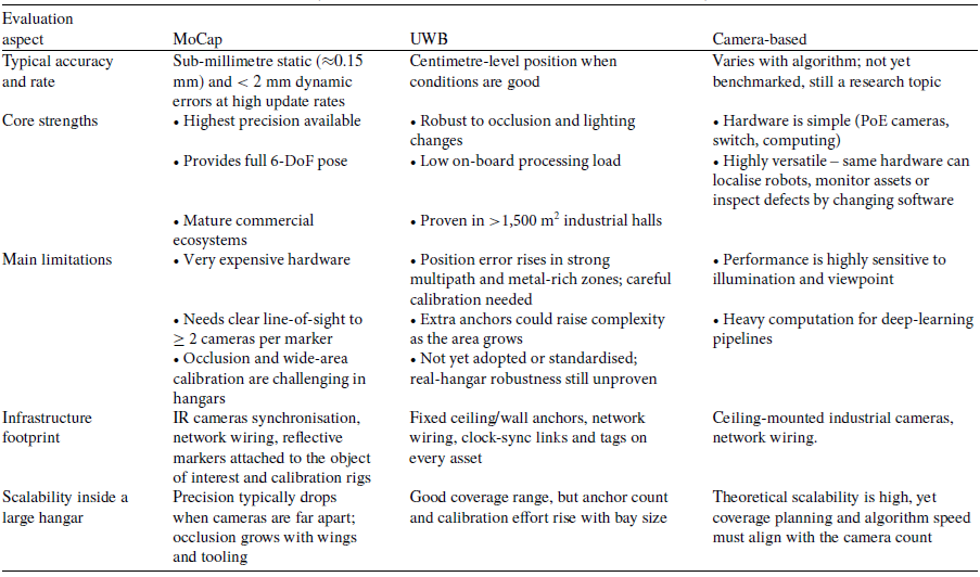
This section brings together the assessments of MoCap, UWB and CMC systems relying on cameras discussed earlier into a streamlined comparison matrix. Table 2 contrasts their fundamental abilities, infrastructure requirements and specific trade-offs, providing a clear overview of the performance of each technology within the confines of a large aircraft hangar.
Key characteristics of the three localisation and monitoring systems
3. Optimised and Cost-Effective Camera Selection and Coverage Mapping
The preceding section discussed three potential systems for the smart hangar, namely MoCap, UWB and camera-based solutions. Although the first two options are available on the market, the camera-based system remains an area of open research. This section formalises the algorithmic framework for the camera-based architecture. It addresses how to select a commercially available camera-lens combination and strategically position a minimal number of units to capture the entire area of interest with the necessary ground sampling distance, frame rate and budget, depending on the operational mode (robot localisation, asset monitoring or defect detection). The ensuing framework integrates classical pinhole projection, cost-weighted distortion heuristics and binary set-cover optimisation to translate high-level operational needs into a practical camera deployment layout.
A high-level block diagram of the two-stage optimisation framework for camera selection and placement algorithm.

The process is divided into four steps. Initially, the envelope of the target object, the working distance and the maximum allowable ground sampling distance (GSD) are used to sift through a database of camera–lens pairs for initial feasibility. Second, an objective function balances hardware cost against optical distortion, shutter type, and frame-rate penalties, allowing each surviving pair to be ranked. In the third step, the field-of-view of the chosen pair is projected onto the hangar top-view, where a discretised grid of potential camera centres is created, and a Boolean visibility matrix is constructed. Finally, a mixed-integer linear approach addresses the resulting set-cover problem, determining both the number and positions of cameras needed to achieve full coverage with a specified overlap. Figure 5 depicts a high-level block diagram of the solution.
At first, the algorithm identifies a feasible camera-lens pair to cover a target area at a specified working distance while respecting a requested GSD, budget constraints and an approximate lens distortion penalty. This approach follows the classic pinhole camera model in photogrammetry and computer vision. The premise involves using a singular camera lens setup to observe a flat surface located at a working distance of d (in mm). The camera sensor has physical dimensions ( ${S_w}$
,
${S_w}$
, ${S_h}$
) (in mm), and the lens has a focal length f (in mm). Under the pinhole camera approximation, the field of view (FoV) in each dimension can be calculated by projecting the sensor size onto the object plane at a distance d:
${S_h}$
) (in mm), and the lens has a focal length f (in mm). Under the pinhole camera approximation, the field of view (FoV) in each dimension can be calculated by projecting the sensor size onto the object plane at a distance d:
 \begin{equation}{\mathrm{Fo}}{{\mathrm{V}}_w} = \frac{{d \times {S_w}}}{f},{\mathrm{\;\;\;\;Fo}}{{\mathrm{V}}_h} = \frac{{d \times {S_h}}}{f}\end{equation}
The diagonal FoV is defined as:
 \begin{equation} {\mathrm{Fo}}{{\mathrm{V}}_{{\mathrm{diag}}}} = \sqrt {{{({\mathrm{Fo}}{{\mathrm{V}}_w})}^2} + {{({\mathrm{Fo}}{{\mathrm{V}}_h})}^2}} \end{equation}
In photogrammetry, GSD represents the real-world size of one pixel in the captured image. If the camera resolution in the horizontal direction is ${R_w}$
pixels (width) and
${R_w}$
pixels (width) and ${R_h}$
pixels (height), the GSD in each dimension is:
${R_h}$
pixels (height), the GSD in each dimension is:
 \begin{equation}{\mathrm{GS}}{{\mathrm{D}}_w} = \frac{{{\mathrm{Fo}}{{\mathrm{V}}_w}}}{{{R_w}}},{\mathrm{\;\;\;\;GS}}{{\mathrm{D}}_h} = \frac{{{\mathrm{Fo}}{{\mathrm{V}}_h}}}{{{R_h}}}\end{equation}
To maintain adequate spatial resolution in the images, these values should remain below a user-defined maximum GSD limit, denoted as ${\mathrm{GS}}{{\mathrm{D}}_{{\mathrm{max}}}}$
. Although the camera specifications lack distortion coefficients, it remains possible to implement a distortion minimisation strategy using estimations and heuristic methods. An uncomplicated method is to presume that larger fields of view result in increased distortion. The corresponding equation is as follows:
${\mathrm{GS}}{{\mathrm{D}}_{{\mathrm{max}}}}$
. Although the camera specifications lack distortion coefficients, it remains possible to implement a distortion minimisation strategy using estimations and heuristic methods. An uncomplicated method is to presume that larger fields of view result in increased distortion. The corresponding equation is as follows:
 \begin{equation} D = \frac{{{\mathrm{Fo}}{{\mathrm{V}}_{{\mathrm{diag}}}}}}{f}\end{equation}
A larger diagonal FoV for a given focal length f implies a higher distortion metric D. Although simplistic, this metric provides a convenient scalar measure to compare different camera lens configurations. The best combination of camera lenses for monitoring a target area is determined using a minimal optimisation algorithm. This algorithm considers factors such as working distance, desired coverage area, pixel density and budget constraints. The primary objective is to reduce overall costs while meeting all operational needs. Assuming that the camera cost is ${{\mathrm{C}}_{{\mathrm{cam}}}}$
and the lens cost is
${{\mathrm{C}}_{{\mathrm{cam}}}}$
and the lens cost is ${C_{{\mathrm{lens}}}}$
, the definition of the total cost is the following.
${C_{{\mathrm{lens}}}}$
, the definition of the total cost is the following.
 \begin{equation}{C_{{\mathrm{total}}}} = {C_{{\mathrm{cam}}}} + {C_{{\mathrm{lens}}}}\end{equation}
To select among feasible camera-lens pairs, a potential multi-objective function can be:
 \begin{equation} O = {C_{{\mathrm{total}}}} + \alpha D - \beta \cdot {\mathrm{GS}} + \gamma \cdot {\mathrm{FPSpenalty}}\end{equation}
where GS denotes the presence of a global shutter (binary variable), and FPS refers to the frame-per-second rate of the camera. Using this approach, the aim is to rank feasible options by combining hardware cost, distortion, shutter type preference and frame rate stability. The constants $\alpha $
,
$\alpha $
, $\beta $
and
$\beta $
and $\gamma $
allow tuning of trade-offs between distortion, shutter preference and temporal resolution. More specifically, the parameter
$\gamma $
allow tuning of trade-offs between distortion, shutter preference and temporal resolution. More specifically, the parameter $\alpha $
is a user-chosen weight to balance monetary cost versus the distortion penalty D. In practice, the parameter
$\alpha $
is a user-chosen weight to balance monetary cost versus the distortion penalty D. In practice, the parameter $\alpha $
may be chosen according to the desired level of penalisation for wide fields of view or lens distortion. The parameter
$\alpha $
may be chosen according to the desired level of penalisation for wide fields of view or lens distortion. The parameter $\beta $
assigns a cost-reduction bonus to configurations that include a global shutter sensor. This reflects the practical advantage of global shutters in avoiding motion blur during dynamic operations, making them more suitable for applications involving moving objects. The parameter
$\beta $
assigns a cost-reduction bonus to configurations that include a global shutter sensor. This reflects the practical advantage of global shutters in avoiding motion blur during dynamic operations, making them more suitable for applications involving moving objects. The parameter $\gamma $
penalises configurations with non-ideal frame rates. Frame rates below 20 FPS may result in choppy visual streams, while rates above 50 FPS are often unnecessary and can increase bandwidth and processing load. This term helps to prioritise configurations that operate within a desirable temporal resolution range.
$\gamma $
penalises configurations with non-ideal frame rates. Frame rates below 20 FPS may result in choppy visual streams, while rates above 50 FPS are often unnecessary and can increase bandwidth and processing load. This term helps to prioritise configurations that operate within a desirable temporal resolution range.
Before applying ranking configurations, a filtering step is applied to discard those that do not meet these fundamental criteria. This ensures that only operationally feasible combinations are passed on to the optimisation process, reducing computational overhead and improving the quality of the result.
In terms of constraints, each candidate configuration must satisfy the following:
-
• Coverage:
(7) \begin{equation} {\mathrm{Fo}}{{\mathrm{V}}_w} \ge {W_{{\mathrm{target}}}},{\mathrm{\;\;\;\;Fo}}{{\mathrm{V}}_h} \ge {H_{{\mathrm{target}}}}\end{equation}
where
${W_{{\mathrm{target}}}}$
and
${H_{{\mathrm{target}}}}$
is the required coverage size (in mm). -
• Resolution:
(8)
\begin{equation} {\mathrm{GS}}{{\mathrm{D}}_w} \le {\mathrm{GS}}{{\mathrm{D}}_{{\mathrm{max}}}},{\mathrm{\;\;\;\;GS}}{{\mathrm{D}}_h} \le {\mathrm{GS}}{{\mathrm{D}}_{{\mathrm{max}}}}\end{equation}
-
• Budget:
(9)
\begin{equation}{C_{{\mathrm{total}}}} \le {C_{{\mathrm{max}}}}\end{equation}
where
${C_{{\mathrm{max}}}}$
is the maximum allowable budget (in British pounds).


Once the desired dimensions for the camera sensor have been determined, the next step is to estimate the FoV of the camera positioned on the ceiling to inspect the aircraft. A geometric model was utilised, taking into account the sensor dimensions and the lens’s focal length. The angular field of view (in degrees) is calculated for both the width and height of the camera sensor using the following equation:
 \begin{equation}{\mathrm{FoV}} = 2 \cdot {\mathrm{ta}}{{\mathrm{n}}^{ - 1}}\left( {\frac{s}{{2f}}} \right) \cdot \left( {\frac{{180}}{\pi }} \right)\end{equation}
where
-
• s is the sensor dimension (width or height) in millimetres
-
• f is the focal length in millimetres
During the space allocation phase, accurately scaling the aircraft’s shape to real dimensions is crucial. The two most popular original equipment manufacturers (OEMs) provide online catalogues of their aircraft models, commonly called 3-view drawings, which are used for gate planning purposes [42, 43]. The drawings are provided in the Drawing eXchange Format (DXF) and include the top, side, and front perspectives. However, the presentation of these drawings exhibits inconsistency, both between different OEMs but also between different models produced by the same manufacturer.
The suggested algorithm necessitates that the aircraft’s top view is represented as a closed polygonal line. To form this polygon, the procedure involves importing the 3-view drawing into a vector drawing application, that supports Scalable Vector Graphics (SVG) and manually outlining the perimeter polygon on a new layer above the image. Since this task must be performed only once per aircraft model, it is not considered a heavy or unsustainable task within the suggested process flow.
Once the exterior representation of a narrow-body aircraft is obtained in SVG format, it is parsed, and an ordered vertex list is created.
 \begin{equation} \mathcal{V} = \left\{ {\left( {{x_i},{y_i}} \right)} \right\}_{i = 1}^N\end{equation}
with N the number of vertices. Assuming that ${L_{{\mathrm{px}}}}$
is the pixel length of the fuselage,
${L_{{\mathrm{px}}}}$
is the pixel length of the fuselage,
 \begin{equation} {L_{{\mathrm{px}}}} = \mathop {{\mathrm{max}}}\limits_i {x_i} - \mathop {{\mathrm{min}}}\limits_i {x_i},\end{equation}
and let ${L_{\mathrm{m}}}$
be the length of the aircraft. The metric scale factor is therefore
${L_{\mathrm{m}}}$
be the length of the aircraft. The metric scale factor is therefore
 \begin{equation} \alpha = \frac{{{L_{\mathrm{m}}}}}{{{L_{{\mathrm{px}}}}}}{\mathrm{\;\;}},{\mathrm{\;\;\;\;\;\;\;\;}}\left( {x_i^{\mathrm{*}},y_i^{\mathrm{*}}} \right) = \left( {\alpha {x_i},{\mathrm{\;\;}}\alpha {y_i}} \right).\end{equation}
The reference polygon (Fig. 9(a)) can be defined by the scaled vertex as
 \begin{equation} \mathcal{P} = poly\left\{ {\left( {x_i^{\mathrm{*}},y_i^{\mathrm{*}}} \right)} \right\} \subset {\mathbb{R}^2}.\end{equation}
To guarantee safe stand-off for cameras or for the aircraft model, an external inspection envelope was introduced, $\mathcal{P}$
is uniformly offset by a Minkowski sum with radius
$\mathcal{P}$
is uniformly offset by a Minkowski sum with radius $\delta $
:
$\delta $
:
 \begin{equation} {\mathcal{P}^ + } = \{ {\mathbf{p}} \in {\mathbb{R}^2}|dist\left( {{\mathbf{p}},\mathcal{P}} \right) \le \delta \} .\end{equation}
This is like inflating the perimeter of the plane by a specific distance (Fig. 9(b)). In the next stage, a discretisation of the region of interest occurs. A regular square grid of spacing
 \begin{equation} \Delta = \lambda \end{equation}
is seeded over the bounding rectangle of ${\mathcal{P}^ + }$
. The parameter
${\mathcal{P}^ + }$
. The parameter $\Delta$
defines the granularity, but also affects the computation time of the approach. Let
$\Delta$
defines the granularity, but also affects the computation time of the approach. Let
 \begin{equation} {\mathbb{G}_{\Delta}} = \{ \left( {x,y} \right) \in {\mathbb{R}^2}|x = {x_{{\mathrm{min}}}} + k\Delta,{\mathrm{\;\;}}y = {y_{{\mathrm{min}}}} + \ell \Delta\} \end{equation}
be that lattice. The set of target points is determined by a Boolean flag based on whether interest is directed toward the internal (Fig. 9(c)) or external space (Fig. 9(d)) of the aircraft, depending on the specific scenario.
 \begin{equation}{\mathbf{G}} = \left\{\begin{matrix}\{ g \in \mathbb{G}_{\Delta}| \mathbf{g} \in \mathcal{P}^{+}\}, \qquad \mathrm{internal} \ \mathrm{coverage}\\\{ g \in \mathbb{G}_{\Delta}| \mathbf{g} \notin \mathcal{P}^{+}\}, \qquad \mathrm{external} \ \mathrm{coverage}\\\end{matrix}\right.\end{equation}
The cameras are mounted at a hangar ceiling height of h and possess horizontal and vertical fields of view. In a pinhole model, the ground footprint of one camera is the rectangle $\left[ { - \frac{W}{2},\frac{W}{2}\left] \times \right[ - \frac{L}{2},\frac{L}{2}} \right]$
with
$\left[ { - \frac{W}{2},\frac{W}{2}\left] \times \right[ - \frac{L}{2},\frac{L}{2}} \right]$
with
 \begin{equation} W = 2h{\mathrm{tan}}\left( {{\theta _h}/2} \right),{\mathrm{\;\;\;\;\;\;\;\;}}L = 2h{\mathrm{tan}}\left( {{\theta _v}/2} \right).\end{equation}
Let each ceiling-mounted camera project a ground-plane footprint of width $W$
and length
$W$
and length $L$
$L$
 \begin{equation}{\Delta_x} = \beta W,{\mathrm{\;\;\;\;\;\;\;\;}}{\Delta_y} = \beta L.\end{equation}
The parameter $\beta \in \left( {0,1} \right]$
is defined as overlap ratio. This corresponds to a ground-plane footprint overlap of
$\beta \in \left( {0,1} \right]$
is defined as overlap ratio. This corresponds to a ground-plane footprint overlap of $\left( {1 - \beta } \right)$
in each axis, or equivalently,
$\left( {1 - \beta } \right)$
in each axis, or equivalently, $\left( {1 - \beta } \right) \times 100{\mathrm{\% }}$
overlap. For example,
$\left( {1 - \beta } \right) \times 100{\mathrm{\% }}$
overlap. For example, $\beta = 0.80$
produces an overlap of
$\beta = 0.80$
produces an overlap of $20{\mathrm{\% }}$
between adjacent camera footprints. In this work, the overlap defines the region of shared ground coverage used to support cross-camera handover and track continuity in localisation scenarios. The same formulation allows reduced overlap in static inspection tasks, where object handover is unnecessary.
$20{\mathrm{\% }}$
between adjacent camera footprints. In this work, the overlap defines the region of shared ground coverage used to support cross-camera handover and track continuity in localisation scenarios. The same formulation allows reduced overlap in static inspection tasks, where object handover is unnecessary.
The origin of this lattice is shifted so that it coincides with the centroid of ${\mathcal{P}^ + }$
, ensuring an approximately symmetric layout around the aircraft. Let
${\mathcal{P}^ + }$
, ensuring an approximately symmetric layout around the aircraft. Let $\left\{ {{{\mathbf{c}}_1}, \ldots ,{{\mathbf{c}}_m}} \right\}$
denote all candidate locations generated within the enlarged boundary box. Then, for every point on the grid
$\left\{ {{{\mathbf{c}}_1}, \ldots ,{{\mathbf{c}}_m}} \right\}$
denote all candidate locations generated within the enlarged boundary box. Then, for every point on the grid ${{\mathbf{p}}_i} \in {\mathbf{G}}$
and camera candidate
${{\mathbf{p}}_i} \in {\mathbf{G}}$
and camera candidate ${{\mathbf{c}}_j}$
, an indicator was defined as
${{\mathbf{c}}_j}$
, an indicator was defined as
 \begin{equation} {A_{ij}} = \left\{ {\begin{array}{*{20}{l@{\quad}l}}{1,} {}& {{{\mathbf{p}}_i} \in {\mathrm{Cov}}\left( {{{\mathbf{c}}_j}} \right),}\\{0,} {}& {{\mathrm{otherwise}},}\end{array}} \right.\end{equation}
where ${\mathrm{Cov}}\left( {{{\mathbf{c}}_j}} \right) = {{\mathbf{c}}_j} + \left[ { - \frac{W}{2},\frac{W}{2}\left] \times \right[ - \frac{L}{2},\frac{L}{2}} \right].$
At this stage, the Boolean matrix
${\mathrm{Cov}}\left( {{{\mathbf{c}}_j}} \right) = {{\mathbf{c}}_j} + \left[ { - \frac{W}{2},\frac{W}{2}\left] \times \right[ - \frac{L}{2},\frac{L}{2}} \right].$
At this stage, the Boolean matrix ${\mathbf{A}} \in {\{ 0,1\} ^{n \times m}}$
compactly describes which cameras see which points. A binary decision variable
${\mathbf{A}} \in {\{ 0,1\} ^{n \times m}}$
compactly describes which cameras see which points. A binary decision variable ${x_j} \in \left\{ {0,1} \right\}$
indicate whether the camera
${x_j} \in \left\{ {0,1} \right\}$
indicate whether the camera $j$
is installed. Ultimately, the minimum-camera problem is the classical set cover formulated as a binary integer linear programme:
$j$
is installed. Ultimately, the minimum-camera problem is the classical set cover formulated as a binary integer linear programme:
 \begin{equation} \mathop {{\mathrm{min}}}\limits_{{\mathbf{x}} \in {{\{ 0,1\} }^m}} \mathop \sum \limits_{j = 1}^m {x_j}\end{equation}
 \begin{equation} {\mathrm{subject\ \ to}}\mathop \sum \limits_{j = 1}^m {A_{ij}}{x_j}{\mathrm{\;\;}} \ge 1,{\mathrm{\;\;\;\;\;\;\;\;}}i = 1, \ldots ,n.\end{equation}
Equations (20)–(21) are implemented using the PuLP [Reference Mitchell, O’Sullivan and Dunning44] library with category LpBinary (Linear-programming of binary type) and solved using the CBC MILP (COIN-OR branch-and-cut – mixed-integer linear programming) solver engine [Reference Forrest45]. The optimal index set $\mathcal{C}^{*} = \{j | x^{*}_{j} = 1\} $
specifies both the number and the positions of cameras (Figs. 10–15) required for full coverage of the target region defined in Equation (17).
$\mathcal{C}^{*} = \{j | x^{*}_{j} = 1\} $
specifies both the number and the positions of cameras (Figs. 10–15) required for full coverage of the target region defined in Equation (17).
4. Design-to-Cost Deployment Blueprints
Automated robotic inspection forms an integral part of the smart hangar concept, which utilises Industry 4.0 technologies to augment the abilities of human experts to perform necessary maintenance of the aircraft. The primary focus is on commercial aircraft that can be divided into two major categories. Narrow-body aircraft, also known as single-aisle aircraft, are the workhorses of short- to medium-haul routes. They typically have a single aisle, two or three seats on each side of the aisle, a capacity of 100–240 passengers, and a range of 3,000–4,000 nautical miles. Examples include Boeing 737 series and Airbus A320 family (A318, A319, A320, A321). The second category is the wide-body aircraft, or twin-aisle aircraft, which are designed for long-haul flights and have two aisles, seven to ten seats in economy class, capacity for 200–550 passengers, and a range of 5,000–8,000 nautical miles. Examples include Boeing 767, 777, 787 Dreamliner and Airbus A330, A350 and A380. Figure 6 illustrates the difference in size between the narrow-body and wide-body aircraft.
The size comparison between narrow-body (Airbus A320) and wide-body (A380) aircraft.

Taking into account the analysis presented in Ref. (46) for the distribution of the fleet, the global operating commercial aircraft fleet in 2025 is dominated by narrow-body jets, which account for approximately 62% of the total. Wide-body, regional and turboprop jets are projected to comprise the remaining 38% of the worldwide commercial aircraft fleet.
The hangar dimensions are adjusted to the aircraft dimensions. For example, a hangar intended to host only narrow-body aircraft is required to have a door height of 14 m and an opening of 37 m. In the case of wide-body, the specifications are 24 m in height and 75 m opening. In terms of ceiling height, the first case requires reaching 18 to 20 m, while the second case requires reaching 26–28 m. In addition, the hangars can accommodate more than one aircraft simultaneously, featuring dedicated, predefined spaces called bays. The typical lateral dimensions [35] for a narrow-body aircraft hangar range from 40 × 50 m to 60 × 60 m.
In the following sections, potential architectures are provided for each case. In the MoCap and UWB options, manufacturers provide suggestions for system deployments with an order-of-magnitude cost associated. For the camera-based system, a technical analysis is presented, based on the methodology outlined earlier, along with an estimated cost based on the components.
4.1. MoCap blueprint
The MoCap blueprint is a configuration proposed by a lead manufacturer, tailored specifically for a single-bay narrow-body hangar. The proposal was parameterised by the dimensions of bay width, length and ceiling height. The camera configuration involves installing 12 cameras at a height of 22 m, pointing downward (Fig. 7(a)). Side or low-position cameras are excluded, as they are impractical for hangars with multiple bays. Local occlusions at the wing–fuselage junctions are the dominant risk. Consequently, additional cameras can improve coverage in these regions. This contingency also accounts for operational occlusions (e.g., lifts, tugs, tool trolleys) that are absent from the vendor’s aircraft-only simulation and are expected to be encountered in a real service environment. The 12 cameras effectively cover a distance of about 32 m for a 19-mm marker. The suggested model is a 12MP (300 fps) camera, with a maximum capturing distance of 40 m and a 3D resolution of 0.04 mm. Figure 7(b) shows the capture volume, which demands that each marker be captured by three cameras. In reality, the system can track markers over a broader area than this, although a lower marker resolution might result in occasional tracking loss. In a MoCap system, tracking each marker requires the use of at least two cameras. Figure 7(c) illustrates the capture volume with two-camera tracking, where a larger area is covered toward the nose and tail. In practice, increasing the range of the camera does not provide much benefit. In addition, the size of the marker and the camera range increase proportionally, and markers of 30, 40 and 50 mm are commercially available, depending on the size of the robotic platform selected for the inspection. For hangar-scale volumes, vendors increasingly replace dynamic wanding with fixed-camera calibration referenced to a surveyed control network. In practice, a small set of permanently mounted markers is measured with a total station and entered as control points to the MoCap tracking manager, allowing the solver to recover extrinsics and absolute scale against these surveyed points [Reference Nagymáté and Kiss47]. Independent validations that tie MoCap volumes to geodetic references further support this workflow for large industrial spaces. The projected expense for this system was assessed to fall within the range of £180,000 to £200,000, as stated in the quotation provided by a leading motion capture manufacturer in April 2025.
Top (a): MoCap system with 12 cameras set-up. Bottom left (b): MoCap system with 3-camera minimum tracking for each marker. Capture volume in shaded green. Bottom right (c): MoCap system with 2-camera minimum tracking for each marker.

4.2. UWB blueprint
This blueprint reflects a manufacturer-validated UWB configuration tailored to a single-bay narrowbody hangar, parameterised by bay width, length and ceiling height. Within the UWB coverage of the hangar, the extent of the necessary infrastructure is determined by the specific tracking applications used and the efficiency required in regions with significant obstructions, such as under the wings. In scenarios involving localisation and monitoring, such as the tracking of drones and ground platforms, the process is considerably simpler compared to tracking certain assets (e.g., tools). This is because it typically occurs above or between highly obstructed areas, avoiding locations like under wings. Considering the initial assumption of a single bay maintenance zone sized between 40 × 50 m and 60 × 60 m (resulting in a volume from 2,000 to 3,600 ${{\mathrm{m}}^2}$
) and noting that the application occurs in fairly open settings, a prudent estimate is to account for 10–25 anchors to achieve adequate coverage. For comparison, when applications involve tracking under the wing and fuselage, and around the engines, more sensors, possibly ranging from 20 to 40, might be used.
${{\mathrm{m}}^2}$
) and noting that the application occurs in fairly open settings, a prudent estimate is to account for 10–25 anchors to achieve adequate coverage. For comparison, when applications involve tracking under the wing and fuselage, and around the engines, more sensors, possibly ranging from 20 to 40, might be used.
On the implementation side, power and network connectivity are required for the installation of each anchor. The most common practice involves using a Cat5e UTP Ethernet cable to connect each sensor location from a control room, which needs to be within 100 m of the sensor mounting location to comply with Ethernet networking limits. Given the size of the hangar, this likely necessitates equipment placement in two control rooms, each equipped with a timing distribution unit (TDU) for precise time synchronisation of the anchors and a PoE networking switch to provide power and networking to each sensor. The cost associated with running each cable can vary significantly depending on the location. It is largely determined by whether the cabling is installed during the construction of the hangar or after, whether the installation after construction occurs while the space is active (it is considerably more expensive if the space is active) and the geographical location where this activity occurs. Lastly, the cost of actually mounting the sensor on its bracket at the end of the cable needs to be included.
In order for the system to be completely functional, every object of importance must have a tag installed. A wide range of options are available regarding size, power consumption and update rate. As an illustration, a small tag may feature dimensions of 46 × 42 × 18 mm and weigh about 20 g, with a battery life that exceeds ten years while transmitting continuously at an update rate of 1 Hz. For drone tracking applications, the tags can be configured to transmit at a higher rate (e.g. 10 Hz), wherein the battery life might be approximately 12–15 months. These tags are priced at about £40 each. Another option is to incorporate a tag module into the drone or ground platform. This module draws its power from an external source, such as the drone’s power system, eliminating the need for an internal battery that could run out. Naturally, the drone itself is periodically recharged. Without a battery restriction, the tag module can achieve considerably higher update rates, such as 50 Hz.
The UWB infrastructure is capable of monitoring thousands of tags within its coverage area and can deliver aggregate update rates of several thousand updates each second. The resulting data stream, composed of (ID, x, y, z, timestamp), is available for transmission to other applications. Although system suppliers offer various applications, there is also the possibility of transmitting the data as UDP network data, allowing it to be used by third-party connected systems. According to a quotation from a leading UWB manufacturer issued in May 2025, the configuration of a candidate UWB system to cover a single bay hangar, which encompasses anchors, PoE switches, TDUs, wiring and calibration, is projected to cost approximately £49,000. This estimate is a general figure that may vary depending on the number of anchors used. An example setup of a UWB system is installed at the Digital Aviation Research and Technology Centre (DARTeC) at Cranfield University, where nine anchors and two types of tags with 0.5 and 30 Hz frequencies have been installed (Fig. 8).
The UWB system installed at Cranfield’s DARTeC smart hngar.

4.3. Ceiling-mounted camera system blueprint
The camera-based system is not a commercially available product, so the candidate implementation is not based on the suggestion of any manufacturer. Depending on the application scenario, the algorithms presented in Section 3 suggest a candidate system that can perform the robot localisation, monitoring or defect detection task. In the beginning, extensive product research was performed in order to identify the commercially available products that could be used as data for the analytical approaches. The analysis is focused on industrial machine vision cameras, excluding surveillance or CCTV devices. The automatic adjustments and compressed video streams of surveillance cameras impede precise control over GSD, exposure, timing, and synchronisation, which are essential to achieve reproducible and pixel-level performance.
In system design, camera specifications are crucial for optimal system performance. Beyond selecting the right camera and lens combination, it is essential to consider cost-effectiveness and the need to depict the object of interest at a suitable size for the deep learning component. The chosen camera features that were used as a criterion for the analysis include sensor size and format, resolution, shutter type, pixel dimensions, frame rate, connectivity speed and cost (Table 3). For the lens, the most important characteristic was the focal length (Table 4). The compatibility between the camera and the lens was ensured as both supports the C-mount interface.
The table presents a large selection of PoE cameras. The information was gathered from the Edmund Optics website, and the prices were captured on the 30th of March 2025

The table presents a selection of lenses (C-mount) compatible with the cameras presented in Table 3. The information was gathered from the Edmund Optics website, and the prices were captured on the 30th of March 2025

The machine vision cameras support two connection interfaces: USB 3.0 and PoE. The PoE interface is standardised because it enables both power and data to be transmitted through a single Cat6 cable for distances up to 100 m, facilitating centralised switching and scalable aggregation on a hangar scale. In contrast, ceiling-side compute is forced by USB 3.0 short-reach cabling (or active extenders), making it less suitable for robust hangar installations.
The typical velocity of the target object is associated with the camera frame rate to generate a suitable sequence of frames to track movement. The linked factor that influences system performance is the GigE connectivity interface, which is related to the data transfer rate, latency and overall system throughput. The maximum theoretical data transfer rate of a standard GigE interface is 1 gigabit per second, which is equal to 125 megabytes per second. This determines the maximum frame rate and resolution that a camera can output. So, for example, a 2MP camera outputs uncompressed 8-bit images at 60 fps × 120 MB/s, which is close to the GigE limit. In general, GigE has higher latency compared to USB 3.0 interfaces.
The final attribute evaluated was the shutter type. The global shutter camera takes a complete image in a single instance, as every pixel is exposed at the same time. There is no motion distortion, so fast-moving objects are captured without skew or wobble. This is the ideal case for precise measurements, which is useful in robotics, industrial vision and 3D reconstruction. They can support easier synchronisation with external sensors like LiDAR or IMU, because the timestamp is consistent across the whole image. However, the rolling-shutter camera captures the image line-by-line from top to bottom (or side to side), over a short time interval. Because of this mode of operation, the image contains motion artefacts, which can cause skew, wobble or partial exposure when objects move quickly or the camera moves during capture. In addition, it is harder to sync since different parts of the image correspond to slightly different times.
The video streams from the cameras are transmitted to the computing unit through an Ethernet switch. To facilitate a simpler installation and reduce potential failure points, a PoE switch is suggested instead of using the power supply for each camera separately. When using high-resolution GigE cameras, it is recommended that Ethernet switches and Network Interface Cards (NICs) be used to support jumbo frames. In general, in Ethernet networking, a standard frame has a Maximum Transmission Unit (MTU) of 1,500 bytes. Jumbo frames extend this limit, typically allowing up to 9,000 bytes per frame. This means that more data can be transmitted in a single packet, reducing the number of packets needed for large data transfers. The advantages of utilising Jumbo frames include:
-
• Reduced CPU load: Fewer packets mean fewer interrupts for the CPU to handle, lowering processing overhead.
-
• Improved throughput: Larger frames can carry more data, enhancing overall network efficiency.
-
• Decreased packet loss: With fewer packets on the network, the chance of collisions and packet loss diminishes.
There are many commercial options available that satisfy these requirements. For example, the Mikrotik cloud router switch (CRS328-24P-4S+RM), which offers 24 PoE gigabit ports, with 4 SPF (small form-factor pluggable) ports to connect fibre optics of different types and speeds. This specific device supports 10,218-byte jumbo frames. A representative cost of this device is £417 (price captured from Amazon.co.uk on the 27th of April 2025).
The candidate combinations of camera and lens are fed into the camera selection algorithm. Depending on the target scenario, the algorithm proposes five potential configurations that are illustrated in Table 5.
The table presents the camera-lens optimal combination per target scenario

Notes:
1 Scenario A is related to mid-size defect detection on the surface of the aircraft.
2 Scenario B is related to localisation of drone (column 2) and ground robotic platform (column 3).
3 Scenario C is related to monitoring of ground assets (column 4) and humans (column 5).
Starting with the Airbus A320 aircraft as the base case, the initial step involves obtaining the top-view perimeter from the SVG file. This outline is then scaled to match a total length of 37.6 m, in accordance with the manufacturer’s publicly available specifications. The result is depicted in Fig. 9(a).
The next step involves the extension of the perimeter to create a safe operating envelope to accommodate tolerances related to the target scenario. For instance, in drone localisation, the value is 1 m to include a buffer space for the manoeuvres, but in defect detection, it is 0.5 m as there is no moving target and only aircraft misalignment should be considered. The result is illustrated in Fig. 9(b).
Once the operating envelope is determined based on the specified target scenario, the next step involves discretising the region of interest. In cases where the focus is on the aircraft, such as in drone localisation, the area is transformed into a mosaic pattern based on the set discretisation distance, as demonstrated in Figs 9(c) and (d). Experimental results demonstrated that a value of 0.5 m in grid spacing achieves a balance between solution accuracy and the necessary computational time. Because the coverage discretisation uses a square grid, the number of coverage points grows roughly with the inverse square of the spacing, so the run time increases nearly quadratically as the grid is refined.
In the final stage, the algorithm, considering the discretised region of interest of the previous step and the suggested camera field of view projection, identifies the optimal camera layout for the bay. In the process, an overlap factor was also taken into account. This factor can affect system performance under varying conditions, especially with regard to transferring object localisation between cameras. If the scenario, such as defect localisation, does not necessitate it, the overlap is reduced. This parameter may also prove vital when stitching camera feeds into a larger image, as the presence of shared salient points becomes essential.
Different candidate modes of operation for the CMC system.

Defect detection scenario for the camera-based system.

4.3.1. Scenario A – medium-defect mapping
The initial case of interest involves the detection of defects. This scenario focusses on identifying flaws present on the top surfaces of the aircraft, such as the fuselage and wings. The existing commercial systems, such as UWB and Mocap, are not designed for this scenario as they focus on localisation and tracking through the use of tags or reflective markers. This is notably intriguing because for maintenance technicians, it is safer to avoid working at heights with scaffolding and cherry pickers. Throughout the experimental process, it became apparent that effective identification of small defects using cameras installed on ceilings presents significant physical challenges. This threshold emerged from GSD-based calculations, which indicated that capturing adequate pixel density for small surface features requires extremely high-resolution sensors or a highly concentrated network of cameras. Both options greatly increase costs and complexity. In contrast, focussing on medium-sized defects of size 40 × 40 mm presented a more reasonable and feasible compromise, enabling the system to remain scalable and cost-efficient while still offering significant assistance for general visual inspections. In the medium-size defect case, a potential target will occupy approximately 45 px in the captured image. Given that the targets are located roughly between 16 and 19 m away, corresponding to the aircraft’s upper surface, the proposed configuration encompasses an area of 3 by 3 m. To cover the entire surface of a narrow-body aircraft, 49 cameras are required (Fig. 10). Considering the additional cost of three 24-port PoE Ethernet switches, the cost adds up to a total of £76,809. In this cost estimate, cables are excluded since the installation cable length estimate was beyond the scope of the work. However, a representative price for 100 m of unshielded twisted pair (UTP) Category 6 cable is approximately £60 (price captured from Amazon.co.uk on the 27th April 2025). For this scenario, the cameras were configured to have a 10% overlap in coverage to minimise the number of cameras needed. Moreover, as the target remains stationary, it is unnecessary to maintain a significant margin for the target transition between the cameras. Similarly, since the target is not moving, there is no negative impact that the suggested camera has a rolling shutter or the relatively low frame rate of 25 fps.
Localisation scenario targeting drones for the camera-based system.

4.3.2. Scenario B – localisation for robotic platforms
The significance of the localisation case is considerable, as it functions as an external system supplying the absolute position of a robotic platform, whether aerial or ground. These data can then be integrated with onboard odometry to enhance navigation reliability. Based on the dimensions of the target and the distance from the camera (ceiling), there are two potential cases: drones and ground robotic platforms. Depending on the robot’s operation space, the distance is approximately 15–18 m for the drones and 22 m for the ground platforms.
In this context, it is crucial to confirm that the anticipated and permissible velocity of the platforms is compatible with the frame rate of the cameras. The equations presented in 22 can be used to determine the distance travelled between frames. The camera for drones has 42 fps, and for the UGVs, 35 fps. With a maximum speed of 1.5 m/s, the distance between each frame for a 40 fps camera is 3.75 cm. In addition, both cameras suggested by the algorithm are equipped with a global shutter that is recommended for improved performance on moving targets.
 \begin{equation}{\mathrm{Time per frame}} = \frac{1}{f},{\mathrm{\;\;\;\;Distance per frame}} = v \times {\mathrm{Time per frame}}\end{equation}
In the case of aerial platforms, Fig. 11 illustrates that covering the entire surface of a narrow-body aircraft requires 15 cameras with the specific lenses. The total cost amounts to approximately £16,500 including a 24-port PoE Ethernet switch.
The ground-plane footprint overlap is set at 20% to support cross-camera handover and track continuity for moving robots, that is, to maintain association as targets move between adjacent FoVs. In order to contextualise the chosen overlap ratio within the localisation scenario, the duration of dual visibility available for cross-camera handover is measured by the observed ground-plane fields of view and standard operating conditions.
Localisation scenario targeting ground robotic platforms for the camera-based system.

Assuming that the horizontal (side-to-side) and vertical (longitudinal) footprints of each ceiling-mounted camera are $W = 11.562{\mathrm{\;m}}$
and
$W = 11.562{\mathrm{\;m}}$
and $L = 7.226{\mathrm{\;m}}$
, respectively, as calculated for the selected camera and lens. With an overlap ratio
$L = 7.226{\mathrm{\;m}}$
, respectively, as calculated for the selected camera and lens. With an overlap ratio $r = 0.20$
, the overlap zones are
$r = 0.20$
, the overlap zones are ${d_{{\mathrm{ov}},x}} = rW = 2.3124{\mathrm{\;m}}$
(horizontal adjacency) and
${d_{{\mathrm{ov}},x}} = rW = 2.3124{\mathrm{\;m}}$
(horizontal adjacency) and ${d_{{\mathrm{ov}},y}} = rL = 1.4452{\mathrm{\;m}}$
(vertical adjacency). For a drone with a typical lateral size
${d_{{\mathrm{ov}},y}} = rL = 1.4452{\mathrm{\;m}}$
(vertical adjacency). For a drone with a typical lateral size $s = 0.5{\mathrm{\;m}}$
moving at
$s = 0.5{\mathrm{\;m}}$
moving at $v = 1$
m/s, the conservative full-target co-visibility lane is
$v = 1$
m/s, the conservative full-target co-visibility lane is ${d_{{\mathrm{eff}}}} = {\mathrm{max}}\left( {{d_{{\mathrm{ov}}}} - s,0} \right)$
. Given a frame rate
${d_{{\mathrm{eff}}}} = {\mathrm{max}}\left( {{d_{{\mathrm{ov}}}} - s,0} \right)$
. Given a frame rate $f = 42{\mathrm{\;fps}}$
, based on the selected camera model, the available association time and frame count during handover are
$f = 42{\mathrm{\;fps}}$
, based on the selected camera model, the available association time and frame count during handover are
 \begin{equation} t = \frac{{{d_{{\mathrm{eff}}}}}}{v},{\mathrm{\;\;\;\;\;\;\;\;}}N = ft\end{equation}
Numerically, this yields ${d_{{\mathrm{eff}},x}} = 1.8124{\mathrm{\;m}}$
,
${d_{{\mathrm{eff}},x}} = 1.8124{\mathrm{\;m}}$
, ${t_x} = 1.8124{\mathrm{\;s}}$
, and
${t_x} = 1.8124{\mathrm{\;s}}$
, and ${N_x} \approx 76$
frames for horizontal handover; and
${N_x} \approx 76$
frames for horizontal handover; and ${d_{{\mathrm{eff}},y}} = 0.9452{\mathrm{\;m}}$
,
${d_{{\mathrm{eff}},y}} = 0.9452{\mathrm{\;m}}$
, ${t_y} = 0.9452{\mathrm{\;s}}$
, and
${t_y} = 0.9452{\mathrm{\;s}}$
, and ${N_y} \approx 40$
frames for vertical handover. Therefore, even in the more challenging vertical case (requiring the entire target
${N_y} \approx 40$
frames for vertical handover. Therefore, even in the more challenging vertical case (requiring the entire target $0.5{\mathrm{\;m}}$
to remain within both footprints), the system provides approximately 40 frames of dual visibility in 1 m/s, which is sufficient for robust cross-camera association and handover. This scenario-grounded calculation motivates the use of
$0.5{\mathrm{\;m}}$
to remain within both footprints), the system provides approximately 40 frames of dual visibility in 1 m/s, which is sufficient for robust cross-camera association and handover. This scenario-grounded calculation motivates the use of $r = 0.20$
as it provides reliable handover while avoiding the increase of cameras that higher overlaps entail.
$r = 0.20$
as it provides reliable handover while avoiding the increase of cameras that higher overlaps entail.
In the context of the localisation of the ground robotic platform, the demands for camera specifications pertinent to object detection can be eased due to the increased dimensions, resulting in the installation of eight cameras (Fig. 12). The estimated cost, including a 24-port PoE Ethernet switch, is approximately £12,800. For ground robots, the overlap setting is retained. Due to their wider lateral reach, slower rotational speeds and the planar nature of their trajectories constrained by the ground floor, the pixel size requirement per target is less stringent compared to drones. From an overhead camera viewpoint, the drone’s X-shaped open frame and central payload create a visually fragmented target that poses challenges for segmentation, particularly against the bright, reflective surfaces of the aircraft it inspects. In contrast, ground platforms have solid bodies and traverse the darker hangar floor, providing higher contrast and more stable silhouettes.
Using drones for inspections near the target surface offers an effective solution to the challenges associated with defect detection, which requires multiple cameras, to identify medium to large defects as outlined in Scenario A. Instead of deploying 49 cameras and allocating a budget of around £75,000, a single drone equipped with a camera can detect defects as small as 10 mm (small size defects) with camera equipment costing approximately £2,000.
To effectively demonstrate the comparison, consider the example of a wing inspection. Initially, it is necessary to determine the specifications of the drone’s camera. The assumption is that the drone flies approximately 1 m above the surface under inspection and that the field of view is limited to an area of 1×1 m. This operational setup generates images with appropriately sized artefacts suitable for input into a DL algorithm that has been effectively trained to detect surface defects. Using the camera specification algorithm, as described in Section 3, the Lucid(11) camera equipped with lens(3) can illustrate 10 mm defects at 45 pixels in the captured image.
Another important parameter to take into account is the time required for the drone to completely cover and inspect the area. To approximate this duration, consider the example of the wing area of an A320. Each wing covers approximately 61.3 m ${^2}$
, and combined, the total area for both wings is 122.6 m
${^2}$
, and combined, the total area for both wings is 122.6 m ${^2}$
[48] (Fig. 13). If the drone is photographing 1 m
${^2}$
[48] (Fig. 13). If the drone is photographing 1 m ${^2}$
patch, it needs approximately 61 images. The 122.6 mm
${^2}$
patch, it needs approximately 61 images. The 122.6 mm ${^2}$
figure refers to the flat ‘shadow’ area of the wing. In reality, the upper (and lower) skin of the wing is slightly curved (aerofoil shape), so the total area of the skin is somewhat larger, which can be approximated roughly to 63 m
${^2}$
figure refers to the flat ‘shadow’ area of the wing. In reality, the upper (and lower) skin of the wing is slightly curved (aerofoil shape), so the total area of the skin is somewhat larger, which can be approximated roughly to 63 m ${^2}$
. To thoroughly survey the wing, the drone is generally flown in a ‘lawnmower’ (boustrophedon) pattern [Reference B¨ahnemann49]. This involves making straight, parallel flights separated by 1 m (the camera’s swath), followed by a 180° turn at the end of each line to start the next one. It makes sense to fly each pass along the span (wing tip to wing root) because the A320 half-wing span is about 17.05 m, so each sweep is roughly 17 m long. In this case, covering the entire top of an A320 wing at 0.5 m/s, with a 1 m swath and 5 s per 180° turn, requires on the order of 2.5 minutes total. Although this serves as a basic representation of the coverage pattern, it provides a ballpark estimate that requires additional refinement to accurately reflect the realistic time measurement.
${^2}$
. To thoroughly survey the wing, the drone is generally flown in a ‘lawnmower’ (boustrophedon) pattern [Reference B¨ahnemann49]. This involves making straight, parallel flights separated by 1 m (the camera’s swath), followed by a 180° turn at the end of each line to start the next one. It makes sense to fly each pass along the span (wing tip to wing root) because the A320 half-wing span is about 17.05 m, so each sweep is roughly 17 m long. In this case, covering the entire top of an A320 wing at 0.5 m/s, with a 1 m swath and 5 s per 180° turn, requires on the order of 2.5 minutes total. Although this serves as a basic representation of the coverage pattern, it provides a ballpark estimate that requires additional refinement to accurately reflect the realistic time measurement.
The Airbus A320 wings (Source online in Ref. (50)). The area of both wings is 122.6 m2.

4.3.3. Scenario C – ground assets and human monitoring
The monitoring case focusses on tracking moving assets on the ground, including ground support vehicles, personnel, tool cribs, ground power units (GPUs) and tugs. Typically, height assumptions for viewing depth range from 1 to 2 m, resulting in an average distance of 21.5 m from the ceiling. From an overhead perspective, there is a significant difference in the area occupied by a vehicle compared to that of a human (Table 1). This is why the camera specifications are designed separately for the two distinct scenarios. The maximum speed allowed for terrestrial vehicles is 2 m/s, while the typical average walking speed for a person is about 1.27 m/s. In the first case, the chosen camera records 5 cm per frame, while in the second case, it captures 9.4 cm per frame. For ground vehicles, four cameras are necessary (Fig. 14); however, if the targets include humans, the requirement increases to nine cameras (Fig. 15). The price, which includes a 24-port PoE Ethernet Switch, is approximately £8,800 and £17,200, respectively.
Monitoring scenario targeting ground support vehicles for the camera-based system.

Monitoring scenario including humans for the camera-based system.

4.3.4. Comparative blueprint synthesis
To consolidate the design-to-cost blueprints discussed, Table 6 contrasts the five scenarios of the CMC system with the MoCap and UWB reference systems. The snapshot highlights how the intended application, bill-of-materials footprint, and technology maturity interact with overall budget, providing a concise decision aid for hangar planners.
In the context of localisation, the three systems tackle the same fundamental issue but employ different physical principles and enabling technologies. MoCap systems achieve the highest fidelity in pose estimation, offering static errors within a submillimetre range and orientation accuracy below one degree, with update frequencies exceeding 100 Hz. This precision depends on maintaining simultaneous visibility of markers to infrared cameras. MoCap systems are a relatively expensive infrastructure.
UWB systems achieve centimetre-level accuracy, generally less than 10 cm, operating at frequencies of tens of hertz using ToF ranging between fixed anchors and tags. Although a single tag cannot directly determine orientation, using multiple tags on the object could be used to infer the relative rotations. UWB remains effective regardless of lighting conditions. Nonetheless, substantial multi-path interference and dense metal obstructions in a hangar can influence range measurements. Economically, UWB technology is positioned at an intermediate cost level.
The CMC system blueprint differs because the target asset does not require a tag or marker. However, models utilised for machine vision reasoning must be trained on representative datasets. One camera grid configuration can establish the exact location of a drone or ground robot within a single bay, another setup can monitor tugs and personnel on the floor and a more intricate and high-resolution layout can inspect the upper surfaces of the aircraft. The system’s performance metrics are influenced by the choice of hardware and the vision model optimisation. There is no commercial solution available for comparison.
Comparison of localisation and monitoring blueprints proposed

Note:
1 The price estimate for the CMC system excludes cables, mounts, and computing units.
There are trade-offs to consider between these systems. Firstly, in terms of accuracy and maturity, the MoCap and UWB designs are high-TRL, vendor-supported solutions, exhibiting predictable performance in industrial environments. In contrast, the camera-based system is low-TRL, and its accuracy in localisation, robustness to occlusion and long-term stability in reflective and dynamic hangars remain areas of research. Secondly, regarding temporal behaviour, MoCap regularly surpasses 100 Hz, and UWB tags can operate at several tens of hertz. The proposed camera set-up operates at a few tens of frames per second, which is usually sufficient to track slow-moving objects. Third, in observability, the CMC system estimates both the position and orientation of a rigid body, while UWB requires multiple tags to determine orientations. Lastly, regarding scalability and coverage, the UWB and MoCap systems are restricted to detecting specifically tagged or marked objects. In contrast, once installed, a CMC system can observe everything within its view, having been trained for such targets. This extensive visibility aids in safety and coordination on the ground, but raises issues around data governance and privacy, especially with respect to personnel monitoring.
The comparison of the systems indicates that each one has its own strengths and weaknesses based on the specific requirements. MoCap is the reference for high-accuracy ground-truth and precision robotics localisation. UWB is a mature option for tracking assets and platforms without relying on vision. The CMC system is a flexible system capable of tasks ranging from localising robots and personnel to visually inspecting aircraft surfaces. However, it remains the least developed and relies heavily on strong perception algorithms.
5. Conclusions
This study presents the first comprehensive techno-economic analysis for localisation, artefact detection, and monitoring within a smart hangar. Rigorously benchmarking MoCap, UWB and CMC systems across three representative scenarios–robot location, asset tracking, and surface defect detection – enables the demonstration of the interactions between accuracy, coverage and cost within a 40 × 50 m bay. The proposed two-stage optimisation framework for camera selection and placement combines market-driven camera lens selection with optimisation algorithms, demonstrating how a CMC system can be deployed in various operational scenarios. Design-to-cost case studies demonstrate that only 15 global-shutter GigE cameras are sufficient for drone localisation, 9 for monitoring, whereas 49 high-resolution units enable complete airframe midsize defect mapping.
These findings have immediate practical value for MRO planners. The blueprint table furnishes a ready-made bill-of-materials envelope, reducing specification time and derisking procurement. Future work should address two open challenges. First, large-scale certification will require extended endurance trials to characterise failure modes under dense reflections and dynamic occlusions. Second, development and validation of the customised deep-learning approaches to support the camera-based solution back-end. Resolving these issues will propel the transition from isolated demonstrators to fully integrated smart hangars in which sensing infrastructures, robots and human technicians collaborate seamlessly to enhance safety, turnaround time and sustainability.
Acknowledgments
We extend our gratitude to Martin Lewis and Andy Ward for their invaluable support and insights on commercially available systems.

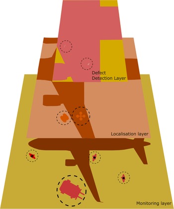
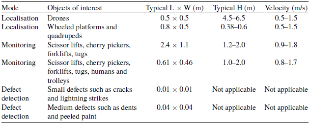


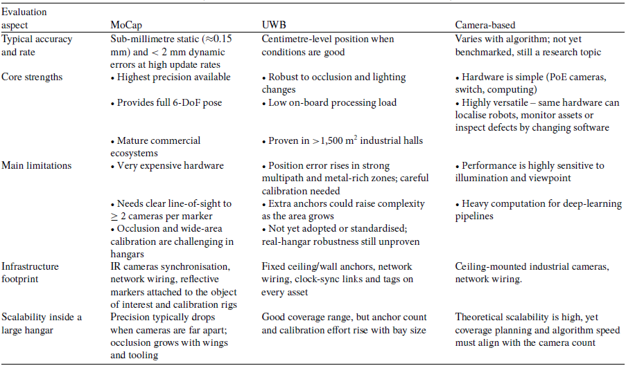
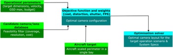
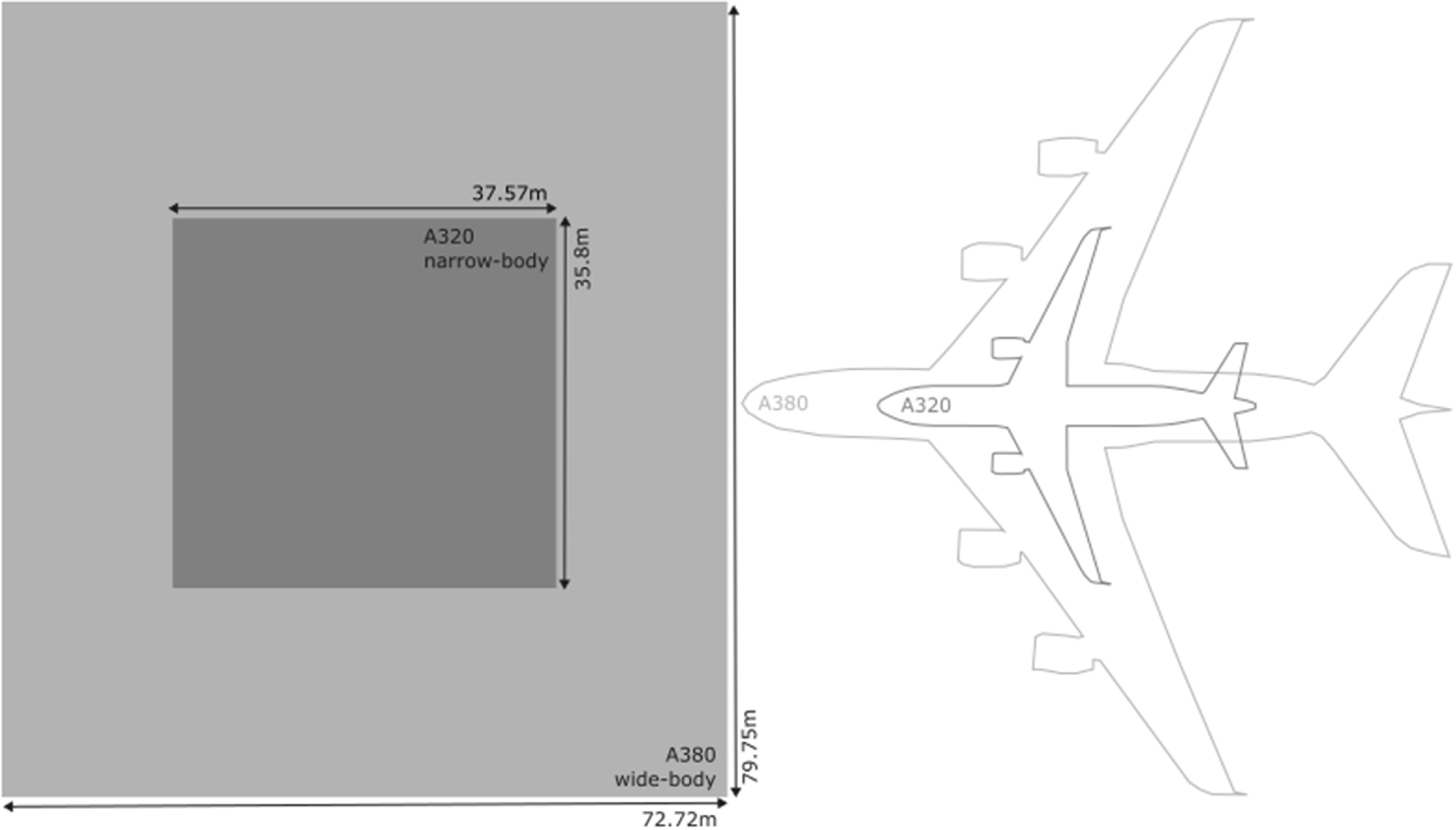


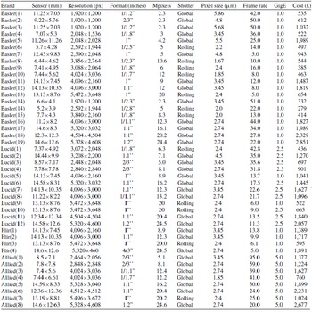
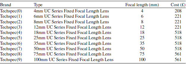
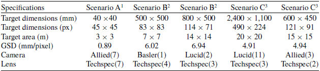


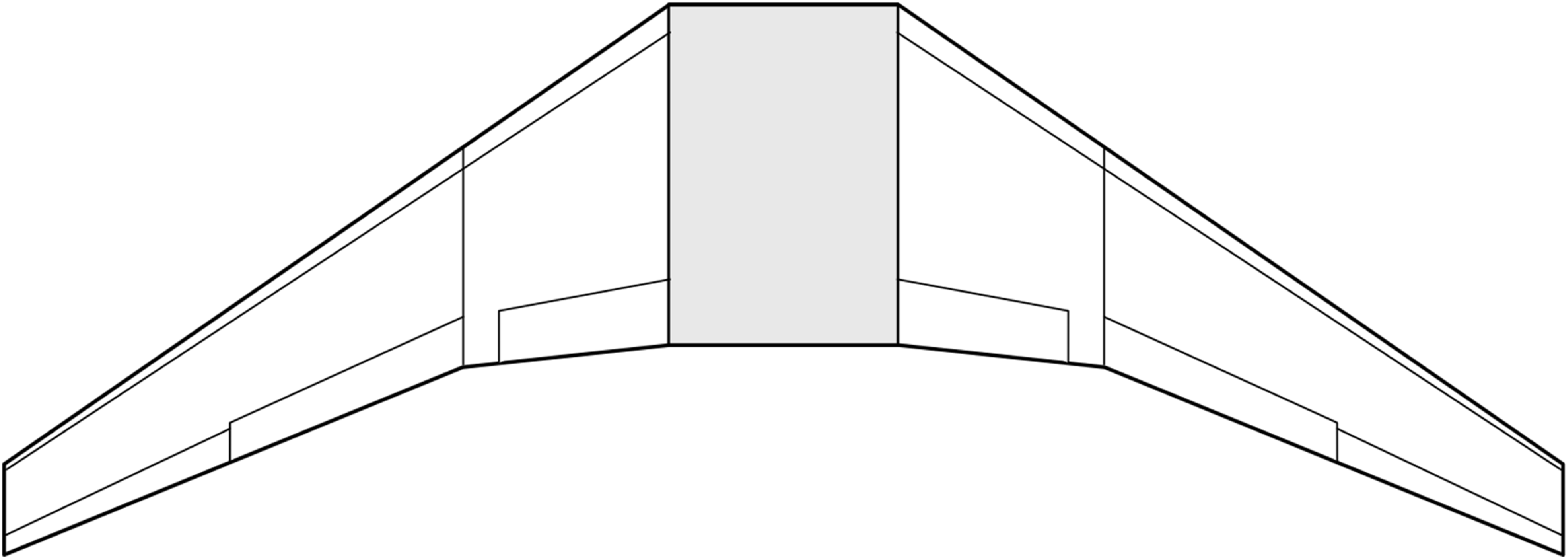


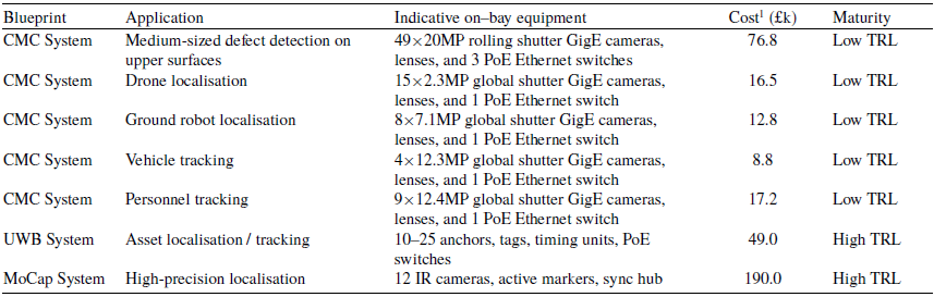

 Open access

