

1. INTRODUCTION
Synchrotron radiation (SR) and undulator radiation (UR) have been attracting researcher's attention for more than half a century. The reasons for that varied with time passing as the challenges for the scientists evolved and the technical progress stepped forwards. UR was predicted by Ginzburg (Reference Ginzburg1947) and then discovered by Motz et al. (Reference Motz, Thon and Whitehurst1953) in the middle of the 20th century. During the following 70 years its theory was developed and refined (Artcimovich & Pomeranchuk, Reference Artcimovich and Pomeranchuk1945; Bordovitsyn, Reference Bordovitsyn1999; Ternov et al., Reference Ternov, Mikhailin and Khalilov1985; Alferov et al., Reference Alferov, Bashmakov and Bessonov1973; Alferov et al., Reference Alferov, Bashmakov and Cherenkov1989). Now UR is again in focus due to the request for coherent X-ray sources [see, e.g., Bessonov et al. (Reference Bessonov, Gorbunkov, Ishkhanov, Kostryukov, Maslova, Shvedunov, Tunkin and Vinogradov2008)], while free electron lasers (FEL) extend to X-range [see McNeil & Thompson (Reference McNeil and Thompson2010)]. Both, SR and UR are due to the radiation of relativistic electrons, executing curved trajectories (Sokolov & Ternov, Reference Sokolov, Ternov and Kilmister1986). The difference between them is in the length on which the radiation is formed: Short part of the circle for UR and the full length of the undulator for the UR. This determines the fundamental difference in the quality of the radiation obtained from these two sources: Short pulses with very broad spectrum for the SR and relatively long lasting radiation bursts with narrow spectrum for the UR (Mikhailin, Reference Mikhailin2013). Nowadays the research frontier is represented by studies of ultra-short attosecond time intervals and Roentgen range (Feldhaus & Sonntag, Reference Feldhaus and Sonntag2009; Zholents, Reference Zholents2005). To achieve these characteristics, the devices require extremely high quality and intense magnetic fields, long undulators with many periods (Korchuganov, Reference Korchuganov, Sveshikov, Smolyakov and Tomin2010). In order to obtain high-frequency radiation, sometimes undulator periodic structure with double or even triple period are used (Bessonov, Reference Bessonov2007; Mishra et al., Reference Mishra, Gehlot and Hussain2009; Tripathi & Mishra Reference Tripathi and Mishra2011; Zhukovsky, Reference Zhukovsky, Chua and Toh2012; Zhukovsky, Reference Zhukovsky2015a
, Reference Zhukovsky
d
), facilitating control over high harmonics and regulating their emission (Alferov et al., Reference Alferov, Bashmakov and Cherenkov1989; Dattoli et al., Reference Dattoli, Mikhailin, Ottaviani and Zhukovsky2006a
, Reference Dattoli, Srivastava and Zhukovsky
b
). Maintaining best quality UR line is important. Unfortunately, even in the most modern undulators the emission lines inevitably broaden due to a number of reasons, first of all due to the electron beam energy spread and the beam divergency, as well as due to inhomogeneity of the periodic magnetic field in undulators. They may have internal or external origin (Walker, Reference Walker1993; Onuki & Elleaume, Reference Onuki and Elleaume2003; Hussain et al., Reference Hussain, Gupta and Mishra2009; Reiss, Reference Reiss1980), but their presence is eminent also due to the fact that the ideal $\vec H = H_0 \sin (2{\rm \pi} z/{\rm \lambda} )$
periodic magnetic field simply does not satisfy Maxwell equations. The electron energy spread is most common detrimental factor; some researchers even concluded that the spectral properties of higher UR harmonics should be limited only by the electron beam properties and not by the undulators (Vagin et al., Reference Vagin, Englisch, Müller, Schöps and Tischer2011). The role of the divergency was underlined, for example, in Smolyakov (Reference Smolyakov1991); Walker (Reference Walker1993). At the same time the constant magnetic field shifts the resonance frequencies and causes loss of intensity (Dattoli et al., Reference Dattoli, Mikhailin and Zhukovsky2008; Dattoli et al., Reference Dattoli, Mikhailin and Zhukovsky2009; Mikhailin et al., Reference Mikhailin, Zhukovsky and Kudiukova2014; Hussain & Mishra, Reference Hussain and Mishra2015). Distortions and losses are particularly pronounced in long undulators (Zhukovsky, Reference Zhukovsky2014a
; Zhukovsky, Reference Zhukovsky2015c
; Zhukovsky, Reference Zhukovsky2016a
).
$\vec H = H_0 \sin (2{\rm \pi} z/{\rm \lambda} )$
periodic magnetic field simply does not satisfy Maxwell equations. The electron energy spread is most common detrimental factor; some researchers even concluded that the spectral properties of higher UR harmonics should be limited only by the electron beam properties and not by the undulators (Vagin et al., Reference Vagin, Englisch, Müller, Schöps and Tischer2011). The role of the divergency was underlined, for example, in Smolyakov (Reference Smolyakov1991); Walker (Reference Walker1993). At the same time the constant magnetic field shifts the resonance frequencies and causes loss of intensity (Dattoli et al., Reference Dattoli, Mikhailin and Zhukovsky2008; Dattoli et al., Reference Dattoli, Mikhailin and Zhukovsky2009; Mikhailin et al., Reference Mikhailin, Zhukovsky and Kudiukova2014; Hussain & Mishra, Reference Hussain and Mishra2015). Distortions and losses are particularly pronounced in long undulators (Zhukovsky, Reference Zhukovsky2014a
; Zhukovsky, Reference Zhukovsky2015c
; Zhukovsky, Reference Zhukovsky2016a
).
In what follows we will compare the contributions of all sources of broadening in various undulator schemes employing precise analytical treatment of the UR by means of extended forms of special functions of Airy and Bessel type. We will explore the role of the various broadening terms accounting for the real size and the emittance of the electron beam, for the energy spread and for the constant field component. We will show the effect of the undulator length on the spontaneous harmonic emission and demonstrate partial compensation of the beam divergences by constant magnets. In conclusion we will also evaluate FEL performance with account for our analysis.
2. BROADENING CONTRIBUTIONS EFFECT ON THE UR
To compute the spontaneous UR we suppose that the following conditions, common in modern undulators, are satisfied: The electrons are ultrarelativistic γ ≫ 1, which is natural in contemporary accelerators, they have small transverse momentum β⊥ ≪ 1, ${\rm \beta} _{\rm \bot} H_{\rm \parallel} \ll H_{\rm \bot} $
,
${\rm \beta} _{\rm \bot} H_{\rm \parallel} \ll H_{\rm \bot} $
, $\vec E = 0$
, moreover, the electric field is absent. It is commonly known that UR from a planar undulator (for a schematic drawing of a planar undulator, see Fig. 1) with N periods of λ0 with the undulator parameter k = (e/mc
2)(H
0/k
λ) and the sinusoidal magnetic field H
y
= H
0 sin (k
λ
z), where k
λ = 2π/λ0, has the peak frequencies
$\vec E = 0$
, moreover, the electric field is absent. It is commonly known that UR from a planar undulator (for a schematic drawing of a planar undulator, see Fig. 1) with N periods of λ0 with the undulator parameter k = (e/mc
2)(H
0/k
λ) and the sinusoidal magnetic field H
y
= H
0 sin (k
λ
z), where k
λ = 2π/λ0, has the peak frequencies
 $${\rm \omega} _{\rm n} = n{\rm \omega} _{\rm R} = \displaystyle{{2n{\rm \omega} _0 {\rm \gamma} ^2} \over {1 + k^2 /2 + ({\rm \gamma} {\rm \psi} )^2}}, \quad {\rm \omega} _{{\rm R0}} = \displaystyle{{2{\rm \omega} _0 {\rm \gamma} ^2} \over {1 + k^2 /2}},\quad {\rm \omega} _{{\rm n0}} = n{\rm \omega} _{{\rm R0}}, $$
where ${\rm \omega} _0 = k_{\rm \lambda} {\rm \beta} _z^0 c$
,
${\rm \omega} _0 = k_{\rm \lambda} {\rm \beta} _z^0 c$
, ${\rm \beta} _z^0 = 1 - (1/2{\rm \gamma} ^2 )(1 + k^2 /2)$
is the average drift speed of the electrons along the undulator axis and ψ is off the undulator axis angle. The shape of the UR emission line is described by the detuning parameter
${\rm \beta} _z^0 = 1 - (1/2{\rm \gamma} ^2 )(1 + k^2 /2)$
is the average drift speed of the electrons along the undulator axis and ψ is off the undulator axis angle. The shape of the UR emission line is described by the detuning parameter
 $${\rm \nu} _{\rm n} = 2{\rm \pi} Nn\left( {\displaystyle{{\rm \omega} \over {{\rm \omega} _{\rm n}}} - 1} \right)$$
and constitutes (sinνn/2)/(νn/2) function. The homogeneous bandwidth, sometimes called half-width of UR spectrum line at its half-height or simply half-width is (Δω/ω n0) = (1/2nN) (green line in Fig. 2) and the half-width is (Δω/ωn0) = (ω − ωn0/ωn0) = (1/nN) (blue line in Fig. 2). In real devices 1/nN ≪ 1.
Schematic drawing of a planar undulator.

UR line and its homogeneous bandwidth, influenced by the shift due to the constant magnetic field.

The shape and the intensity of the UR strongly depends on constant magnetic constituents H
x
= ρH
0, H
y
= κH
0, ρ, κ = constant. For ultrarelativistic beams the longitudinal component H
z
= δH
0 is irrelevant, since it effects in higher orders of k/γ than the transversal magnetic component H
d = H
0κ1,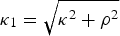 ${\rm \kappa} _1 = \sqrt {{\rm \kappa} ^2 + {\rm \rho} ^2} $
(Dattoli et al., Reference Dattoli, Mikhailin and Zhukovsky2009; Mikhailin et al., Reference Mikhailin, Zhukovsky and Kudiukova2014; Zhukovsky, Reference Zhukovsky2014b
). The latter bends the electrons trajectory into the effective angle
${\rm \kappa} _1 = \sqrt {{\rm \kappa} ^2 + {\rm \rho} ^2} $
(Dattoli et al., Reference Dattoli, Mikhailin and Zhukovsky2009; Mikhailin et al., Reference Mikhailin, Zhukovsky and Kudiukova2014; Zhukovsky, Reference Zhukovsky2014b
). The latter bends the electrons trajectory into the effective angle ${\rm \theta} _{\rm H} = (2/\sqrt 3 )(k/{\rm \gamma} ){\rm \pi} N{\rm \kappa} _1 $
and causes the spectrum shift as demonstrated by dashed lines in Figure 2. The effect of H
d, expressed in terms of θH, is accumulated all along the undulator axis and, therefore, the undulator length L matters. The trajectories of an electron in an undulator in a reference frame, moving at the electron drift speed in an undulator between the 1st and 3rd periods and between the 100th and 102nd periods are shown in Figure 3 with account for the constant magnetic components. The deviation due to κ = ρ = 10−4 from the undulator axis z, where (x, y) = (0, 0), is evident and exceeds the electron oscillations more than 20 times. This raises question about the coherency of the oscillations at the end of the undulator. We will explore it in what follows.
${\rm \theta} _{\rm H} = (2/\sqrt 3 )(k/{\rm \gamma} ){\rm \pi} N{\rm \kappa} _1 $
and causes the spectrum shift as demonstrated by dashed lines in Figure 2. The effect of H
d, expressed in terms of θH, is accumulated all along the undulator axis and, therefore, the undulator length L matters. The trajectories of an electron in an undulator in a reference frame, moving at the electron drift speed in an undulator between the 1st and 3rd periods and between the 100th and 102nd periods are shown in Figure 3 with account for the constant magnetic components. The deviation due to κ = ρ = 10−4 from the undulator axis z, where (x, y) = (0, 0), is evident and exceeds the electron oscillations more than 20 times. This raises question about the coherency of the oscillations at the end of the undulator. We will explore it in what follows.
The electron trajectory in an undulator with the constant magnetic components κ = ρ = 10−4 in the reference frame, moving with mean velocity ${\rm \beta} _z^0 c$
between the 1st and the 3rd (left figure) and between the 100th and 102nd (right figure) periods.
${\rm \beta} _z^0 c$
between the 1st and the 3rd (left figure) and between the 100th and 102nd (right figure) periods.

Qualitative estimations give the following answer. The electron in constant magnetic field H executes a circle of radius R ≅ 3.3E[GeV]/B[T]. The field curves the trajectory in an arc of a length L = Nλ
u
and produces the bent angle ϕ = L/R. The product γϕ ≅ 6Nλ
u
[m]H
0 [T]κ1 of the actual length of the undulator L with the magnetic field strength H
0 is decisive. The observer, looking at the curved trajectory, must take into account the angular width of the undulator. If the latter is small, compared with the above estimated curvature, the observer views the radiation of the electron from the whole trajectory, if it is significant, then only from the part of it. This results in partial coherence of the emitted radiation. The deviation off the axis in the angle ψ has similar effect. Broadening parameters μi ≡ (Δω/ωn)i/(Δω/ωn0), where i the factor, responsible for the broadening (Δω/ωn)i, qualitatively describes the UR losses (Mikhailin et al., Reference Mikhailin, Zhukovsky and Kudiukova2014; Zhukovsky, Reference Zhukovsky2014b
) through the total broadening $[{\rm \Delta} {\rm \omega} /{\rm \omega}_{\rm n}]_{{\rm Tot}} = ({\rm \Delta} {\rm \omega} /{\rm \omega} _{{\rm n0}} )\sqrt {1 + {\rm \mu} _{\rm e}^2 + {\rm \mu} _{\rm H}^2 + ({\rm \mu} _x^2 + {\rm \mu} _y^2 )} $
and consists of the electron energy spread
$[{\rm \Delta} {\rm \omega} /{\rm \omega}_{\rm n}]_{{\rm Tot}} = ({\rm \Delta} {\rm \omega} /{\rm \omega} _{{\rm n0}} )\sqrt {1 + {\rm \mu} _{\rm e}^2 + {\rm \mu} _{\rm H}^2 + ({\rm \mu} _x^2 + {\rm \mu} _y^2 )} $
and consists of the electron energy spread $\sqrt {{\rm \sigma} _{\rm e}} $
contribution
$\sqrt {{\rm \sigma} _{\rm e}} $
contribution ${\rm \mu}_{\rm e} \equiv ({\rm \Delta} {\rm \omega} /{\rm \omega}_{\rm n} )_{\rm e} /({\rm \Delta} {\rm \omega} /{\rm \omega}_{{\rm n0}}) \approx 4Nn \sqrt {{\rm \sigma}_{\rm e}}$
, that of the constant magnetic field μH = Nn(γθH)2/(1 + k
2/2), where
${\rm \mu}_{\rm e} \equiv ({\rm \Delta} {\rm \omega} /{\rm \omega}_{\rm n} )_{\rm e} /({\rm \Delta} {\rm \omega} /{\rm \omega}_{{\rm n0}}) \approx 4Nn \sqrt {{\rm \sigma}_{\rm e}}$
, that of the constant magnetic field μH = Nn(γθH)2/(1 + k
2/2), where ${\rm \theta} _{\rm H} = (2/\sqrt 3 )(k/{\rm \gamma} ){\rm \pi} N{\rm \kappa} _1 $
and that of the angular divergences Θ
x,y
= ε
x,y
/σ
x,y
of the beam, where ε
x,y
are the emittances of the beam, σ
x,y
are the beam sizes (Dattoli, Reference Dattoli1993), yielding
${\rm \theta} _{\rm H} = (2/\sqrt 3 )(k/{\rm \gamma} ){\rm \pi} N{\rm \kappa} _1 $
and that of the angular divergences Θ
x,y
= ε
x,y
/σ
x,y
of the beam, where ε
x,y
are the emittances of the beam, σ
x,y
are the beam sizes (Dattoli, Reference Dattoli1993), yielding ${\rm \mu} _{x,y} = (nN{\rm \gamma} ^2 {\rm \Theta} _{x,y}^2 )/(1 + k^2 /2)$
. Other effects can be similarly included, but they play minor role. The role of the angles θH and Θ
x,y
in the concept of the broadening parameters is the same, while in reality they can interplay with subtle consequences (Zhukovsky, Reference Zhukovsky2014a
, Reference Zhukovsky
c
). The account for focusing magnetic components (Dattoli, Reference Dattoli1993; Quattromini et al., Reference Quattromini, Artioli, Di Palma, Petralia and Giannessi2012), inherent in undulators, can be done based upon the maximum value of the corresponding magnetic field:
${\rm \mu} _{x,y} = (nN{\rm \gamma} ^2 {\rm \Theta} _{x,y}^2 )/(1 + k^2 /2)$
. Other effects can be similarly included, but they play minor role. The role of the angles θH and Θ
x,y
in the concept of the broadening parameters is the same, while in reality they can interplay with subtle consequences (Zhukovsky, Reference Zhukovsky2014a
, Reference Zhukovsky
c
). The account for focusing magnetic components (Dattoli, Reference Dattoli1993; Quattromini et al., Reference Quattromini, Artioli, Di Palma, Petralia and Giannessi2012), inherent in undulators, can be done based upon the maximum value of the corresponding magnetic field: $H_{{\rm MAX\_f}} = 2H_0 ({\rm \gamma} /k)^2 L^2 ({\rm \varepsilon} _x^3 /{\rm \sigma} _x^5 )({\rm \varepsilon} _y /{\rm \sigma} _y )$
(Zhukovsky, Reference Zhukovsky2014b
). Extensive discussion of the contribution of each of these broadening factors can be found, for example, in Zhukovsky (Reference Zhukovsky2014a
, Reference Zhukovsky
b
, Reference Zhukovsky
c
). The broadening coefficients in modern undulators, aimed on working in high frequency FELs, can be or comparable with each other order and each may amount to 0.5. If
$H_{{\rm MAX\_f}} = 2H_0 ({\rm \gamma} /k)^2 L^2 ({\rm \varepsilon} _x^3 /{\rm \sigma} _x^5 )({\rm \varepsilon} _y /{\rm \sigma} _y )$
(Zhukovsky, Reference Zhukovsky2014b
). Extensive discussion of the contribution of each of these broadening factors can be found, for example, in Zhukovsky (Reference Zhukovsky2014a
, Reference Zhukovsky
b
, Reference Zhukovsky
c
). The broadening coefficients in modern undulators, aimed on working in high frequency FELs, can be or comparable with each other order and each may amount to 0.5. If $\sum {{\rm \mu} _{\rm i} \ge 1} $
, the UR line broadening and reduction become significant.
$\sum {{\rm \mu} _{\rm i} \ge 1} $
, the UR line broadening and reduction become significant.
3. INTENSITY AND SPECTRUM OF THE TWO-FREQUENCY UNDULATOR RADIATION
More precise account for the losses can be done with the help of the generalized special functions of the Bessel type $J_n^{(m)} (x_0, x_1, x_2, x_3 )$
(Dattoli et al., Reference Dattoli, Mikhailin and Zhukovsky2008) and of the Airy-type
$J_n^{(m)} (x_0, x_1, x_2, x_3 )$
(Dattoli et al., Reference Dattoli, Mikhailin and Zhukovsky2008) and of the Airy-type $S({\rm \alpha}, {\rm \beta}, {\rm \eta} ) \equiv \int_0^1 {d{\rm \tau} e^{i({\rm \alpha} {\rm \tau} + {\rm \eta} {\rm \tau} ^2 + {\rm \beta} {\rm \tau} ^3 )}} $
(Zhukovsky, Reference Zhukovsky, Chua and Toh2012). These functions arise naturally in problems, related to SR and beam propagation (Dattoli et al., Reference Dattoli, Mikhailin and Zhukovsky2008; Zhukovsky, Reference Zhukovsky2014d
). They are closely related to the generalized Hermite polynomials (Gould & Hopper, Reference Gould and Hopper1962), which appear in pure mathematical studies (Dattoli et al., Reference Dattoli, Srivastava and Zhukovsky2005; Dattoli et al., Reference Dattoli, Mikhailin, Ottaviani and Zhukovsky2006a
, Reference Dattoli, Srivastava and Zhukovsky
b
; Zhukovsky, Reference Zhukovsky2016b
) and in a wide range of solutions for physical problems from SR and UR studies (Dattoli et al., Reference Dattoli, Mikhailin and Zhukovsky2008) to heat and mass transfer (Zhukovsky, Reference Zhukovsky2015b
; Zhukovsky, Reference Zhukovsky2016c
, Reference Zhukovsky
d
). In a weak constant field with κ ≪ 1 generalized Airy functions simplify on the axis. We calculate the UR intensity, following the radiation integral formula of classical electrodynamics (Jackson, Reference Jackson1975; Landau & Lifshits, Reference Landau and Lifshits1975):
$S({\rm \alpha}, {\rm \beta}, {\rm \eta} ) \equiv \int_0^1 {d{\rm \tau} e^{i({\rm \alpha} {\rm \tau} + {\rm \eta} {\rm \tau} ^2 + {\rm \beta} {\rm \tau} ^3 )}} $
(Zhukovsky, Reference Zhukovsky, Chua and Toh2012). These functions arise naturally in problems, related to SR and beam propagation (Dattoli et al., Reference Dattoli, Mikhailin and Zhukovsky2008; Zhukovsky, Reference Zhukovsky2014d
). They are closely related to the generalized Hermite polynomials (Gould & Hopper, Reference Gould and Hopper1962), which appear in pure mathematical studies (Dattoli et al., Reference Dattoli, Srivastava and Zhukovsky2005; Dattoli et al., Reference Dattoli, Mikhailin, Ottaviani and Zhukovsky2006a
, Reference Dattoli, Srivastava and Zhukovsky
b
; Zhukovsky, Reference Zhukovsky2016b
) and in a wide range of solutions for physical problems from SR and UR studies (Dattoli et al., Reference Dattoli, Mikhailin and Zhukovsky2008) to heat and mass transfer (Zhukovsky, Reference Zhukovsky2015b
; Zhukovsky, Reference Zhukovsky2016c
, Reference Zhukovsky
d
). In a weak constant field with κ ≪ 1 generalized Airy functions simplify on the axis. We calculate the UR intensity, following the radiation integral formula of classical electrodynamics (Jackson, Reference Jackson1975; Landau & Lifshits, Reference Landau and Lifshits1975):
 $$\displaystyle{{d^2 I} \over {d{\rm \omega} d{\rm \Omega}}} = \displaystyle{{e^2} \over {4{\rm \pi} ^2 c}}\left \vert {{\rm \omega} \int\limits_{ - \infty} ^\infty {\left[ {\vec n \times \left[ {\vec n \times \vec {\rm \beta}} \right]} \right]\exp \left[ {i{\rm \omega} \left( {t - \vec n\vec r/c} \right)} \right]dt}} \right \vert ^2, $$
where $\vec n \cong ({\rm \psi} \cos {\rm \varphi}, {\rm \psi} \sin {\rm \varphi}, 1 - {\rm \psi} ^2 /2)$
is the observation vector for γ ≫ 1. The result for a one-frequency undulator is just the particular case of the following double frequency undulator with the magnetic field
$\vec n \cong ({\rm \psi} \cos {\rm \varphi}, {\rm \psi} \sin {\rm \varphi}, 1 - {\rm \psi} ^2 /2)$
is the observation vector for γ ≫ 1. The result for a one-frequency undulator is just the particular case of the following double frequency undulator with the magnetic field
 $$\vec H = H_0 ({\rm \rho}, {\rm \kappa} + \sin (k_{\rm \lambda} z) + d\sin (hk_{\rm \lambda} z),0),\quad h \in {\rm integers}{\rm.} $$
Two-frequency undulators have been studied and used for harmonic adjustments (Bessonov, Reference Bessonov2007; Mishra et al., Reference Mishra, Gehlot and Hussain2009; Tripathi & Mishra, Reference Tripathi and Mishra2011; Zhukovsky, Reference Zhukovsky, Chua and Toh2012; Zhukovsky, Reference Zhukovsky2015a
, Reference Zhukovsky
c
). Helical two-frequency undulator has, perhaps, most flexible design, but it does not allow complete cancellation of undesired harmonics. It is best suited for two color FELs with elliptically polarized radiation as done in Dattoli et al. (Reference Dattoli, Mirian, DiPalma and Petrillo2014); Mirian et al. (Reference Mirian, Dattoli, DiPalma and Petrillo2014). We recall that with equal periods on each line of poles the single harmonic generation is possible, but at the expense of the frequency reduction, since the effective undulator parameter becomes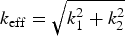 $k_{{\rm eff}} = \sqrt {k_1^2 + k_2^2} $
. In what follows we will perform comprehensive analytical exploration of the properties of the harmonic radiation from a planar two-frequency undulator Eq. (4) with account for all relevant losses, including beam divergency, its compensation, and energy spread in the beam. The goal of this study is to demonstrate that such planar undulator, being not much more difficult to construct than helical, provides much wider range of facilities in terms of harmonic regulation. While the polarization of the emitted radiation is evidently limited to one plane, the emitted harmonics can be adjusted better than in its helical counterpart. Expectedly, radiation from the undulator Eq. (4) has only x – component; calculating the radiation integral Eq. (3), we obtain the intensity of the linearly polarized radiation with account for the field H
d:
$k_{{\rm eff}} = \sqrt {k_1^2 + k_2^2} $
. In what follows we will perform comprehensive analytical exploration of the properties of the harmonic radiation from a planar two-frequency undulator Eq. (4) with account for all relevant losses, including beam divergency, its compensation, and energy spread in the beam. The goal of this study is to demonstrate that such planar undulator, being not much more difficult to construct than helical, provides much wider range of facilities in terms of harmonic regulation. While the polarization of the emitted radiation is evidently limited to one plane, the emitted harmonics can be adjusted better than in its helical counterpart. Expectedly, radiation from the undulator Eq. (4) has only x – component; calculating the radiation integral Eq. (3), we obtain the intensity of the linearly polarized radiation with account for the field H
d:
 $$\eqalign{& \left. {\displaystyle{{d^2 I} \over {d{\rm \omega} d{\rm \Omega}}}} \right \vert _{\left( {\displaystyle{{H_{\rm d}} \over {H_0}}} \right)^{\!\!2} \ll \displaystyle{1 \over {(4{\rm \pi} N)^2}}} \cong \displaystyle{{e^2 N^2 {\rm \gamma} ^2} \over c}\displaystyle{{k^2} \over {(1 + k_{{\rm eff}}^2 /2)^2}} \;\times \cr & \sum\limits_{n = - \infty} ^\infty {n^2} \left[ {S({\rm \nu} _{\rm n}, {\rm \beta}, {\rm \eta} )\left( {T_{{\rm n} - 1} + T_{{\rm n} - 1} + \displaystyle{d \over h}(T_{{\rm n + h}} + T_{{\rm n - h}} )} \right)} \right]^2,} $$
where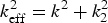 $k_{{\rm eff}}^2 = k^2 + {k}_2^2 $
, k
2 = k |d/h| and T
n is the generalized Bessel function
$k_{{\rm eff}}^2 = k^2 + {k}_2^2 $
, k
2 = k |d/h| and T
n is the generalized Bessel function
 $$T_{\rm n} (\arg ) = \int\limits_0^{2{\rm \pi}} {\displaystyle{{d{\rm \phi}} \over {2{\rm \pi}}} \cos n\left[ {\matrix{ {{\rm \phi} + \displaystyle{{k^2 \sin (2{\rm \phi} )} \over {4(1 + k_{{\rm eff}}^2 /2)}} - \displaystyle{{dk^2 \sin ((h - 1){\rm \phi} )} \over {h(h - 1)(1 + k_{{\rm eff}}^2 /2)}}} \cr {\displaystyle{{dk^2 \sin ((h + 1){\rm \phi} )} \over {h(h + 1)(1 + k_{{\rm eff}}^2 /2)}} - \displaystyle{{d^2 k^2 \sin (2h{\rm \phi} )} \over {4h^3 (1 + k_{{\rm eff}}^2 /2)}}} \cr}} \right]}, $$
The arguments of the special function S(νn, β, η) are the detuning parameter νn Eq. (2), ${\rm \beta} = (2{\rm \pi} nN + {\rm \nu} _{\rm n} )({\rm \gamma} {\rm \theta} _{\rm H} )^2 /(1 + k_{{\rm eff}}^2 /2 + ({\rm \gamma} {\rm \theta} _{\rm H} )^2 )$
and η = 2π2
N
2 (κ cos φ − ρ sin φ)(ω/ω0)(k/γ)ψ. The UR spectrum with account for two undulator periods and for the broadening contributions becomes
${\rm \beta} = (2{\rm \pi} nN + {\rm \nu} _{\rm n} )({\rm \gamma} {\rm \theta} _{\rm H} )^2 /(1 + k_{{\rm eff}}^2 /2 + ({\rm \gamma} {\rm \theta} _{\rm H} )^2 )$
and η = 2π2
N
2 (κ cos φ − ρ sin φ)(ω/ω0)(k/γ)ψ. The UR spectrum with account for two undulator periods and for the broadening contributions becomes
 $$\eqalign{{\rm \omega} _{\rm n} & = n{\rm \omega} _{\rm R} \cr & = \displaystyle{{2n{\rm \omega} _0 {\rm \gamma} ^2} \over {1 + \displaystyle{{k_{{\rm eff}}^2} \over 2} + ({\rm \gamma} {\rm \psi} )^2 + ({\rm \gamma} {\rm \theta} _{\rm H} )^2 - {\rm \gamma} ^2 {\rm \theta} _{\rm H} {\rm \psi} \sqrt 3 \displaystyle{{{\rm \rho} \sin {\rm \varphi} - {\rm \kappa} \cos {\rm \varphi}} \over {{\rm \kappa} _1}}}}}, $$
where φ is the polar angle. The last term in the denominator of the above expression allows for the partial compensation of the horizontal and the vertical divergences by half when applying proper vertical and horizontal constant magnetic components, respectively. The latter produce the effective bending angle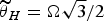 $\widetilde{{\rm \theta}} _H = {\rm \Omega}\sqrt 3 /2 $
and reduce the divergency from ψ to ψ/2:
$\widetilde{{\rm \theta}} _H = {\rm \Omega}\sqrt 3 /2 $
and reduce the divergency from ψ to ψ/2:
 $$\eqalign{\widetilde{{\rm \theta}} _{\rm H} & = \mp {\rm \psi} \displaystyle{{\sqrt 3} \over 2}\displaystyle{{\rm \kappa} \over {{\rm \kappa} _1}}, \;{\rm for}\;{\rm \varphi} = 0,{\rm \pi} \;{\rm and}\;\widetilde{{\rm \theta}} _{\rm H} = \pm {\rm \psi} \displaystyle{{\sqrt 3} \over 2}\displaystyle{{\rm \rho} \over {{\rm \kappa} _1}}, \;{\rm for}\;{\rm \varphi} \cr & = \pm \displaystyle{{\rm \pi} \over 2}}.$$
In the case of a common planar undulator with single period magnetic field, we just set d = 0 in the above formulae Eqs. (5)–(7). Then we obtain the intensity Eq. (5) in terms of common Bessel functions: T
n,x
= (J
n+1/2 (ξ/8) + J
n+1/2 (ξ/8)), where J
(n±1)/2 (ξ/8). The broadening affects mostly higher harmonics, which are of primary interest in the case of a double frequency undulator. The parameters d and h are frequently chosen so that d/h < 1 and they influence rather the harmonic interference than the UR line shape. Indeed, for harmonic regulation, for example, in Dattoli et al. (Reference Dattoli, Mikhailin, Ottaviani and Zhukovsky2006a
, Reference Dattoli, Srivastava and Zhukovsky
b
) they chose h = 3, 5 and d = ± 0.5. The strength of the additional field H
d should be kept low, obeying the approximate condition $H_{\rm d} \lt H_{\max} \cong H_0 /({\rm \pi} N)^{3/2} \sqrt {(3/n)((1/2) + (1/k^2 ))} $
(Zhukovsky, Reference Zhukovsky2014b
). For example, for the 3rd harmonic we obtain, H
max,n=3,k=2,N=150 ≅ 10−4
H
0, which is in agreement with Zhukovsky (Reference Zhukovsky2014a
, Reference Zhukovsky
c
) and with our following study. Indeed, the UR line does not improve for H
d > 10−4
H
0. For the undulator with the amplitude of the periodic field H
0 = 5 kG we have the value H
max, ≅ 0.5 G, which is of the order of the strength of the magnetic field of the Earth, and therefore this last should not be neglected.
$H_{\rm d} \lt H_{\max} \cong H_0 /({\rm \pi} N)^{3/2} \sqrt {(3/n)((1/2) + (1/k^2 ))} $
(Zhukovsky, Reference Zhukovsky2014b
). For example, for the 3rd harmonic we obtain, H
max,n=3,k=2,N=150 ≅ 10−4
H
0, which is in agreement with Zhukovsky (Reference Zhukovsky2014a
, Reference Zhukovsky
c
) and with our following study. Indeed, the UR line does not improve for H
d > 10−4
H
0. For the undulator with the amplitude of the periodic field H
0 = 5 kG we have the value H
max, ≅ 0.5 G, which is of the order of the strength of the magnetic field of the Earth, and therefore this last should not be neglected.
4. REGULATION OF HARMONIC RADIATION IN A TWO-FREQUENCY UNDULATOR
New UR sources, including FEL with self-amplified spontaneous emission (SASE) and with high-gain harmonic generation (HGHG), use high UR harmonics. Other segmented devices with chicanes need as pure single harmonic as possible. In any of the cases they demand high-quality beams and spontaneous UR with selected harmonics. Isolated single harmonic radiation is also important for spectroscopy. Some exotic undulators with multiple periodic fields of linear and of orthogonal polarizations were proposed to produce more intense high harmonics (Dattoli et al., Reference Dattoli, Mikhailin, Ottaviani and Zhukovsky2006a , Reference Dattoli, Srivastava and Zhukovsky b ; Mishra et al., Reference Mishra, Gehlot and Hussain2009). However, the supposed theoretical advantage (Hussain et al., Reference Hussain, Gupta and Mishra2009; Mirian et al., Reference Mirian, Dattoli, DiPalma and Petrillo2014) of their generation in such schemes may not always be achieved because of the losses as we have noted in the previous section. In what follows we shall study the facilities of the UR harmonics tuning in the undulator Eq. (4) with account for major sources of broadening. To calculate them precisely we exploit the expressions Eq. (5) and (6), obtained with the help of the formalism of the generalized special functions. Various losses influence the UR harmonics intensity. Qualitative estimations were given in the first section. To perform realistic study with regard to the two-frequency undulator Eq. (4) it is necessary to account as precisely as possible at least for the electron energy spread and for the divergency in the electronic beam. We use the following convolution (Dattoli, Reference Dattoli1993), modified accordingly to account for the angular divergence:
 $$I = \int {\int {d{\rm \varepsilon}} d{\rm \psi} \left( { \vert S\left( {{\rm \nu} _{\rm n} + 4{\rm \pi} nN{\rm \varepsilon}, {\rm \beta}} \right) \vert ^2} \right)\exp [ - {\rm \varepsilon} ^2 /(2{\rm \sigma} _{\rm e}) ]/\sqrt {2{\rm \sigma} _{\rm e}} {\rm \pi} ^{3/2},} $$
where $\sqrt {{\rm \sigma} _{\rm \varepsilon} } $
is the energy spread and νn is the detuning parameter. The analysis of the integrated UR intensity reveals the dependence of the harmonic intensities on the choice of the parameters d and k in Figure 4 for the fundamental frequency, in Figure 5 for the 3rd UR harmonic, in Figure 6 for the 5th harmonic and in Figure 7 for the 7th harmonic.
$\sqrt {{\rm \sigma} _{\rm \varepsilon} } $
is the energy spread and νn is the detuning parameter. The analysis of the integrated UR intensity reveals the dependence of the harmonic intensities on the choice of the parameters d and k in Figure 4 for the fundamental frequency, in Figure 5 for the 3rd UR harmonic, in Figure 6 for the 5th harmonic and in Figure 7 for the 7th harmonic.
The dependence of the fundamental n = 1 UR harmonic intensity on the amplitude of the second periodic undulator field d and on the undulator parameter k for h = 3, N = 150. (Scaled by c/5 · 104 e 2γ2).

The dependence of the 3rd n = 3 UR harmonic intensity on the amplitude of the second periodic undulator field d and on the undulator parameter k for h = 3, N = 150. (Scaled by c/5 · 104 e 2γ2).

The dependence of the 5th n = 5 UR harmonic intensity on the amplitude of the second periodic undulator field d and on the undulator parameter k for h = 3, N = 150. (Scaled by c/5 · 104 e 2γ2).

The dependence of the 7th n = 7 UR harmonic intensity on the amplitude of the second periodic undulator field d and on the undulator parameter k for h = 3, N = 150. (Scaled by c/5 · 104 e 2γ2).

We observe in Figures 4–7 that high (n = 3,5,7) harmonics fade out if d ≅ 0.5 independently from k, while the fundamental harmonic radiation is close to its maximum. This fact can be exploited for cutting off high harmonics. On the other hand, by choosing k = 2.2, d = −1 we get the utmost from the 7th harmonic radiation, which intensity relates to those of the 5th, the 3rd, and the 1st harmonic as 0.6/0.5/0.2/0.05, respectively.
On the contrary, choosing k = 1.5, d = 1, we obtain maximum radiation of the fundamental harmonic, some weaker 3rd harmonic and very weak higher harmonics (see Figs 4–7). Thus, our analysis allows choosing optimal values of the undulator parameters for undulators, specifically designed for high or low harmonic generation.
The comparative behavior of various harmonics is not influenced by the number of periods, which is evident from Figures 8 and 9. The increase of N just expectably raises the intensities.
4.1. Suppression of Undesired Harmonics
Interestingly, the values of d ≈ 0.5 reduce the radiation of all high harmonics in the undulator with h = 3 and it is not sensitive to k and N (compare Figs 5–9). This fact allows effective suppression of high-harmonic emission. Apart from that with the help of the plots in Figures 4–7 one can easily choose parameters d and h of the two-frequency undulator to obtain the best desired harmonic profile, it is worth noting that complete elimination of the 3rd harmonic is possible! In some applications, for example, in FEL with mirrors, the radiation of high harmonics can be harmful and the clean emission of the 1st harmonic is required. This can be achieved in a symmetric helical undulator with equal each other magnetic fields and periods, which produce circular polarized single harmonic. However, the emitted frequency in such device is lower than in a planar undulator with single row of the same magnets, because the effective value of k
2 in a helical undulator becomes double of that of the planar undulator: $k_{{\rm eff}}^2 = k_1^2 + k_2^2 = 2k^2 $
.
$k_{{\rm eff}}^2 = k_1^2 + k_2^2 = 2k^2 $
.
Dependence of the 3rd harmonic intensity on the period number N.

Dependence of the 5th harmonic intensity on the period number N.

In the cases, when the cleanest possible fundamental frequency is needed and it should possibly be high, the two-frequency undulator Eq. (4) with h = 3 can satisfy the demand. We choose k = 1.5 for the maximum of the 1st harmonic according to Figure 4. Then, we find numerically that the 3rd harmonic is totally suppressed I 3 = 0 for d = 0.48061668 (see Fig. 5). The radiation of higher harmonics is strongly suppressed: I 7 ≈ 0.5 10−3, I 5 ≈ 1.5 10−2, as compared with the intensity of the fundamental frequency I 1 ≈ 1.5 10−1. Similarly radiation of other harmonics can be minimized.
4.2. Enhancement of High Harmonics
One of the main arguments for two-frequency undulators is their ability to enhance high-harmonic radiation. For example, for the undulator with h = 3, N = 150 periods, the 5th harmonic is at its maximum for k ≈ 1.75÷2 and d = −1 (see Fig. 6); its intensity exceeds 10−5 c/e 2γ2 units. For k = 2 the intensities of other high harmonics are at their maximum too, while the fundamental frequency is rather weak. Thus, the set of values k = 2, h = 3, d = −1 in the double frequency undulator is favorable for applications, where high harmonics are requested, such as SASE FEL and HGHG FEL. The 7th harmonic exhibits similar to the 5th harmonic behavior; we omit its plot for brevity. The comparative intensity of the harmonics for k = 2, h = 3 is seen in Figure 10. We observe that the intensities of the 5th and of the 7th harmonics for d = −1 exceed that of the fundamental frequency by more than one order of magnitude!
The dependence of the intensities of UR harmonics n = 1 – red line, n = 3 – green line, n = 5 – blue line and n = 7 – lilac line on the amplitude of the second periodic undulator field d in the undulator with k = 2, h = 3, N = 150. (Scaled by c/5 · 104 e 2γ2).

Supposed we can build short period undulator structure, which forms the second periodic magnetic field in Eq. (4), the question rises how much the long period structure in Eq. (4) helps harmonic radiation. To answer it we compare the obtained intensity of high-harmonic radiation from the two-frequency undulator with that, obtained from the planar undulator Eq. (4), where the long period λu field is absent, that is, from the undulator of identical length L, containing only the short periods λu/h with the magnetic field strength dH 0. Let us inspect the 3rd harmonic intensity. For k = 1.5, where the 3rd harmonic is at its maximum (see Fig. 5), d = −1, h = 3, N = 150 we find the intensity from the two-frequency undulator I 3 twoFreq = 0.378761. Same length of the second periodic field alone yields the value I 3 singlFreq = 0.234532. The advantage of the two-frequency undulator in terms of pure intensity is obvious! Further improvement can be made by constant magnetic constituents as described in what follows.
5. LOSSES IN THE RADIATION OF HARMONICS IN THE TWO-FREQUENCY UNDULATOR
The length L = λu
N of the undulator matters as well as k ∝ λu
H
0 and the number n of the UR harmonic. It is interesting to inspect the effect of the mutually opposite magnetic field $H_{\rm d} \cong - {\rm \kappa} H_0 \;{\mathop{\rm sgn}}\; x$
on both sides of the undulator, imposed according to Eq. (8) to reduce the beam divergence. This effect was recognized in Zhukovsky (Reference Zhukovsky2014c
), where vertical constant magnetic component was shown to reduce the horizontal divergence. In Figure 11 we show the line shape of the 3rd harmonic in the two-frequency undulator Eq. (5) with N = 150 undulator periods λu with k = 1.5, N = 150, d = −1, h = 3, with account for the compensating field H
d, beam energy spread and divergency: γψmax = 0.1,
$H_{\rm d} \cong - {\rm \kappa} H_0 \;{\mathop{\rm sgn}}\; x$
on both sides of the undulator, imposed according to Eq. (8) to reduce the beam divergence. This effect was recognized in Zhukovsky (Reference Zhukovsky2014c
), where vertical constant magnetic component was shown to reduce the horizontal divergence. In Figure 11 we show the line shape of the 3rd harmonic in the two-frequency undulator Eq. (5) with N = 150 undulator periods λu with k = 1.5, N = 150, d = −1, h = 3, with account for the compensating field H
d, beam energy spread and divergency: γψmax = 0.1, $\sqrt {{\rm \sigma} _{\rm \varepsilon} } = 5 \cdot 10^{ - 4} $
, plotted versus N and versus the factorized field parameter κ × 104 and νn. The intensity is plotted in absolute units versus the detuning parameter νn and the factorized field parameter κ × 104.
$\sqrt {{\rm \sigma} _{\rm \varepsilon} } = 5 \cdot 10^{ - 4} $
, plotted versus N and versus the factorized field parameter κ × 104 and νn. The intensity is plotted in absolute units versus the detuning parameter νn and the factorized field parameter κ × 104.
The shape of the UR line of the 3rd n = 3 harmonic in the undulator Eq. (4) with k = 1.5, N = 150, d = −1, h = 3, with account for the beam energy spread and divergency γψmax = 0.1, $\sqrt {{\rm \sigma} _{\rm \varepsilon} } = 5 \cdot 10^{ - 4} $
in the presence of the correcting magnetic field
$\sqrt {{\rm \sigma} _{\rm \varepsilon} } = 5 \cdot 10^{ - 4} $
in the presence of the correcting magnetic field $H_{\rm d} = - {\rm \kappa} H_0 \;{\rm sgn}\; x$
. The values are factorized by c/5 · 104
e
2γ2.
$H_{\rm d} = - {\rm \kappa} H_0 \;{\rm sgn}\; x$
. The values are factorized by c/5 · 104
e
2γ2.

We observe that in the presence of the field $H_{\rm d} \cong - 0.6 \cdot 10^{ - 4} H_0 \;{\rm sgn}\; x$
the spread of the 3rd n = 3 harmonic reduces and its frequency returns to the ideal from the detuning in νn = −2 due to the divergency in γψmax = 0.1. Similar effect can be observed for the 5th n = 5 harmonic in Figure 12, which intensity is plotted versus N and versus the factorized field parameter κ × 104 and νn. Most effective in this case appears the field
$H_{\rm d} \cong - 0.6 \cdot 10^{ - 4} H_0 \;{\rm sgn}\; x$
the spread of the 3rd n = 3 harmonic reduces and its frequency returns to the ideal from the detuning in νn = −2 due to the divergency in γψmax = 0.1. Similar effect can be observed for the 5th n = 5 harmonic in Figure 12, which intensity is plotted versus N and versus the factorized field parameter κ × 104 and νn. Most effective in this case appears the field $H_{\rm d} \cong - 0.55 \!\cdot\! 10^{ - 4} H_0 \;{\mathop{\rm sgn}}\; x$
. The improvement of the intensity in 20–30% can be achieved (see Fig. 11, 12 for κ = 0 and κ ≈ 0.6 10−4). For example, the intensity of the 3rd harmonic rises from I3 = 0.378761 to I
3corr = 0.50674.
$H_{\rm d} \cong - 0.55 \!\cdot\! 10^{ - 4} H_0 \;{\mathop{\rm sgn}}\; x$
. The improvement of the intensity in 20–30% can be achieved (see Fig. 11, 12 for κ = 0 and κ ≈ 0.6 10−4). For example, the intensity of the 3rd harmonic rises from I3 = 0.378761 to I
3corr = 0.50674.
The shape of the UR line of the 5th n = 5 harmonic in the undulator Eq. (4) with k = 1.5, N = 150, d = −1, h = 3, with account for the beam energy spread and divergency γψmax = 0.1, $\sqrt {{\rm \sigma} _{\rm \varepsilon} } = 5 \cdot 10^{ - 4} $
in the presence of the correcting magnetic field
$\sqrt {{\rm \sigma} _{\rm \varepsilon} } = 5 \cdot 10^{ - 4} $
in the presence of the correcting magnetic field $H_{\rm d} = - {\rm \kappa} H_0 \;{\rm sgn}\; x$
. The values are factorized by c/5 · 104
e
2γ2.
$H_{\rm d} = - {\rm \kappa} H_0 \;{\rm sgn}\; x$
. The values are factorized by c/5 · 104
e
2γ2.

The intensity of the UR evidently depends on the length of the undulator. However, homogeneous and inhomogeneous broadening contributions unavoidably accumulate along the undulator length and reduce the gain in the undulator. To demonstrate this effect we plot the UR intensity of the 5th harmonic in the undulator Eq. (5) for the number N of its λu long periods versus the detuning parameter νn. In Figure 13 we plot I(N, νn) and account for the following very low beam energy spread and divergency: γψmax = 0.1, $\sqrt {{\rm \sigma} _{\rm e}} = 10^{ - 5} $
. We observe the growth of the intensity of the spontaneous UR along the undulator, plotted versus the number of the undulator periods N and versus the detuning parameter νn. In real life the UR intensity of the 5th harmonic is much lower because of the realistic inhomogeneous and homogeneous losses are rather γψmax = 0.1,
$\sqrt {{\rm \sigma} _{\rm e}} = 10^{ - 5} $
. We observe the growth of the intensity of the spontaneous UR along the undulator, plotted versus the number of the undulator periods N and versus the detuning parameter νn. In real life the UR intensity of the 5th harmonic is much lower because of the realistic inhomogeneous and homogeneous losses are rather γψmax = 0.1, $\sqrt {{\rm \sigma} _{\rm \varepsilon} } = 5 \!\cdot\! 10^{ - 4} $
, so that we obtain very different figure for the 5th harmonic when accounting for them (see Fig. 14). We observe that ≈3 times more intense radiation for N = 150 in Figure 13 than in Figure 14, where homogeneous and inhomogeneous broadening contributions, accumulated along the undulator, reduce the harmonic intensity, plotted versus N and versus νn.
$\sqrt {{\rm \sigma} _{\rm \varepsilon} } = 5 \!\cdot\! 10^{ - 4} $
, so that we obtain very different figure for the 5th harmonic when accounting for them (see Fig. 14). We observe that ≈3 times more intense radiation for N = 150 in Figure 13 than in Figure 14, where homogeneous and inhomogeneous broadening contributions, accumulated along the undulator, reduce the harmonic intensity, plotted versus N and versus νn.
The intensity of the 5th UR harmonic n = 5 versus the number of periods N in the undulator with k = 2, the beam energy spread and divergency γψmax = 0.01, $\sqrt {{\rm \varepsilon} _e} = 10^{ - 5} $
, factorized by c/5 · 104
e
2γ2.
$\sqrt {{\rm \varepsilon} _e} = 10^{ - 5} $
, factorized by c/5 · 104
e
2γ2.

The intensity of the 5th UR harmonic n = 5 versus the number of periods N in the undulator with k = 2, the beam energy spread and divergency γψmax = 0.1, $\sqrt {{\rm \sigma} _{\rm \varepsilon} } = 5 \cdot 10^{ - 4} $
, factorized by c/5 · 104
e
2γ2.
$\sqrt {{\rm \sigma} _{\rm \varepsilon} } = 5 \cdot 10^{ - 4} $
, factorized by c/5 · 104
e
2γ2.

Growth of the intensity of the 3rd UR harmonic in the two-frequency undulator, influenced by broadening, is shown in Figure 15 for comparison with that of the 5th harmonic. It is plotted versus the number of the undulator periods N and the detuning parameter νn. Note that the 3rd harmonic keeps the shape better and grows faster with rising N than the 5th one.
The intensity of the 3rd UR harmonic n = 3 versus the number of periods N in the undulator with k = 2, the beam energy spread and divergency γψmax = 0.1, $\sqrt {{\rm \sigma} _{\rm \varepsilon} } = 5 \cdot 10^{ - 4} $
, factorized by c/5 · 104
e
2γ2.
$\sqrt {{\rm \sigma} _{\rm \varepsilon} } = 5 \cdot 10^{ - 4} $
, factorized by c/5 · 104
e
2γ2.

Stimulated UR from the two-frequency undulators can be calculated with the help of FEL handbooks (see, e.g., Colson et al. (Reference Colson, Pellegrini, Renieri and Arecchi1993); Dattoli et al. (Reference Dattoli, Ottaviani and Pagnutti2007)), based upon the above obtained results for the spontaneous UR and on the design of the FEL. We make use of Dattoli et al. (Reference Dattoli, Ottaviani and Pagnutti2007) and for high-gain SASE FEL, we simulate the emission of the harmonics from the two-frequency undulator Eq. (4), accounting for the homogeneous and the inhomogeneous losses along its length.
The power of FEL radiation along the undulator with account for the losses is plotted in Figure 16. We assume the beam of Siberia 2 installation in the high quality regime with the energy E = 1.3 GeV, spread $\sqrt {{\rm \sigma} _{\rm e}} \cong 3 \!\cdot\! 10^{ - 4} $
, divergency γψmax = 0.07, and the undulator with the period λu = 1 cm, to obtain the fundamental harmonic radiation length λ~1 nm. Note as the 3rd harmonic vanishes for d = 0.48061668 and k = 1.5; the 5th harmonic remains, although not being so strong (see Fig. 16). Its power is more than one order of magnitude lower than it would be in the ideal case without losses. The saturation of the fundamental harmonic at MW power occurs at ~15 m and the 5th harmonic reaches kW power. Moreover, the two-frequency undulator generates roughly 30% more intense 5th harmonic than a proper ultra-short period single frequency undulator of the same length, constructed to generate it at its fundamental frequency. So, the 3rd harmonic is cut off completely by the choice of d = 0.48061668 for k = 1.5; the 5th FEL harmonic although expectedly weak, is present in the UR spectrum. Enhancement of both the 3rd and the 5th harmonics can be achieved by choosing d = – 1 (see Fig. 10). Their amplitude exceeds that of the fundamental harmonic. Even small values of the energy spread
$\sqrt {{\rm \sigma} _{\rm e}} \cong 3 \!\cdot\! 10^{ - 4} $
, divergency γψmax = 0.07, and the undulator with the period λu = 1 cm, to obtain the fundamental harmonic radiation length λ~1 nm. Note as the 3rd harmonic vanishes for d = 0.48061668 and k = 1.5; the 5th harmonic remains, although not being so strong (see Fig. 16). Its power is more than one order of magnitude lower than it would be in the ideal case without losses. The saturation of the fundamental harmonic at MW power occurs at ~15 m and the 5th harmonic reaches kW power. Moreover, the two-frequency undulator generates roughly 30% more intense 5th harmonic than a proper ultra-short period single frequency undulator of the same length, constructed to generate it at its fundamental frequency. So, the 3rd harmonic is cut off completely by the choice of d = 0.48061668 for k = 1.5; the 5th FEL harmonic although expectedly weak, is present in the UR spectrum. Enhancement of both the 3rd and the 5th harmonics can be achieved by choosing d = – 1 (see Fig. 10). Their amplitude exceeds that of the fundamental harmonic. Even small values of the energy spread $\sqrt {{\rm \sigma} _{\rm \varepsilon} } $
and of the divergence γψmax reduce the intensity of high-harmonic radiation.
$\sqrt {{\rm \sigma} _{\rm \varepsilon} } $
and of the divergence γψmax reduce the intensity of high-harmonic radiation.
Evolution of two first non-vanishing SASE FEL harmonics along the two-frequency undulator with k = 1.5, h = 3, d = 0.48061668.

6. CONCLUSIONS
Employing generalized special functions, we obtained accurate expressions for the UR intensity and spectrum with account for major sources of broadening. The beam energy spread and the angular divergency may produce comparable with other broadening contributions. The effect of the constant magnetic components can be of the same order. The angular divergency can be partially compensated by half angle if mutually opposite constant magnetic components are imposed on both sides of the undulator axis. The proper strength of the field H
d has been determined in Eq. (8). Such fields are very effective for high harmonics n = 3, 5, etc. Complete compensation cannot be achieved, since any additional magnetic field eventually disrupts the coherency of the on-axis electron oscillations. These effects are more pronounced in long undulators; they can reach and exceed the electron beam energy spread in undulators with N > 150 and k > 1. Relevant line broadening may be favorable for the FEL mirrors, protecting them from the hard components of the spectrum. Same can be viewed as disadvantage in SASE FEL and HGHG schemes, where high harmonics are needed. The tuning of the harmonics in two-frequency undulators and the limitation of the harmonic gain was demonstrated. Optimized values for the second periodic field in the two-frequency undulator Eq. (4) found for cancellation of the 3rd harmonic and simultaneous amplification of the 5th and reduction of the 7th harmonics. Even for high-quality beam, the losses of the intensity due to comprehensive broadening may amount to 50% for the 5th harmonic. For the high-quality beam with the beam energy spread $\sqrt {{\rm \sigma} _{\rm e}} = 3 \cdot 10^{ - 4} $
and the divergency γψmax = 0.07 we have obtained for a SASE FEL the reduction by one order of magnitude of the high-harmonic power.
$\sqrt {{\rm \sigma} _{\rm e}} = 3 \cdot 10^{ - 4} $
and the divergency γψmax = 0.07 we have obtained for a SASE FEL the reduction by one order of magnitude of the high-harmonic power.



