

Introduction
In the archaeological record, architectural planning that includes specifications of architectural spatial forms prior to construction becomes archaeologically visible with the appearance of stone-built shelters in the late Epipaleolithic period (Natufian sites) in the Levant (Haklay & Gopher Reference Haklay and Gopher2015). Both the planning and the execution of the plan with accuracy were made possible by conceptualizing basic geometric ideas and methods such as circle, centre and compass arm. Subsequently, the early Neolithic period has seen the emergence of substantial built environments in the form of villages and beyond. During the Neolithic period, from its very beginning, large construction projects were built, including the Jericho tower and other non-domestic, communal/collective structures. The archaeological record of these so called ‘special buildings’, found in Neolithic sites throughout the Levant and Cyprus, recapitulates the advances of architectural planning (thought, principles and methods) during this time, as geometric architectural planning is often detectable while analysing their remains. The site of Göbekli Tepe, however, stands out when it comes to the volume of construction endeavours undertaken, among other things, and, as we will show and discuss, the complexity of the planned and built architectural projects.
This study will discuss the building history of the monumental enclosures in the main area of Göbekli Tepe, as well as the chronological relations between them, by applying a preliminary architectural formal analysis that reconstructs aspects of the architectural design processes involved in the construction of these enclosures. We assume that such analysis would shed light on the chaîne opératoire of the enclosures’ construction (mostly the planning, laying out the plan on the ground—and see below, including Figure 8—and initial construction stages) thus enabling a new understanding of the assemblage of these architectural remains. We first present the site and the enclosures of the main area of Göbekli Tepe, then our methodology and the architectural formal analysis, and finally the results of the analysis. The discussion closing this paper concerns questions of architectural planning and the significance of our results vis-à-vis earlier interpretations of the architectural ensemble of the main area at Göbekli Tepe.
Göbekli Tepe
The Pre-Pottery Neolithic site of Göbekli Tepe is located at the summit of a limestone mountain ridge in the Şanlıurfa Province, southeast Turkey. It is a 15 m high artificial mound covering an area of about 9 ha. Excavations carried out in different areas of the site yielded megalithic architecture dated to the twelfth and eleventh millennia cal. bp (tenth and ninth millennia cal. bc: Schmidt Reference Schmidt2010). This paper will focus on the architectural remains excavated in the southeastern part of the site (the main excavation area) under the direction of Klaus Schmidt in the years 1995–2014, on behalf of the German Archaeological Institute and the Museum of Şanlıurfa (O. Dietrich et al. Reference Dietrich, Köksal-Schmidt, Notroff and Schmidt2014; Peters et al. Reference Peters, Schmidt, Dietrich, Pöllath and Smith2014; Schmidt Reference Schmidt2000; Reference Schmidt2001; Reference Schmidt2002a,Reference Schmidtb; Reference Schmidt2003; 2004; Reference Schmidt2006; Reference Schmidt2007; Reference Schmidt2008; Reference Schmidt2010; Reference Schmidt2012). The site is located at the centre of the Fertile Crescent, at the ‘heart’ of the Golden Triangle (Aurenche & Kozlowski Reference Aurenche and Kozlowski2005; Schmidt Reference Schmidt2000) and in the Core Area of plant domestication (Abbo & Gopher Reference Abbo and Gopher2017; Abbo et al. Reference Abbo, Lev-Yadun and Gopher2010; Gopher et al. Reference Gopher, Lev-Yadun, Abbo, Enzel and Bar-Yosef2017; Lev-Yadun et al. Reference Lev-Yadun, Gopher and Abbo2000). It was suggested by the excavator that early layers of the site were built and used by hunter-gatherers, since no domesticated plants or animals have been recovered.
The stratigraphy of the site comprises two main layers. The older Layer III assigned to the Pre-Pottery Neolithic A (PPNA) period is characterized by large curvilinear enclosures, while the younger Layer II assigned to the early and middle Pre-Pottery Neolithic B (PPNB) periods features relatively smaller, rectangular structures, typically with lime-plaster floors (Schmidt Reference Schmidt2002a) and crowded together with shared walls. A third, maybe intermediate layer, marked as ‘uncertain’ on the schematic plan (Fig. 1; O. Dietrich et al. Reference Dietrich, Köksal-Schmidt, Notroff and Schmidt2014, fig. 2), contains small free-standing structures of irregular shape contours, defined both by curvilinear and straight wall segments. Based on a geomagnetic survey, it is estimated that at least 15 more Layer III curvilinear enclosures are scattered throughout the mound (Schmidt Reference Schmidt2003). According to the excavator, the enclosures of Layer III went through a series of backfilling events, interpreted as an intentional ‘burial’ of these round monumental enclosures (Schmidt Reference Schmidt2000). These enclosures are the subject of our analysis here.
The main excavation area: schematic plan. (Modified from O. Dietrich et al. Reference Dietrich, Köksal-Schmidt, Notroff and Schmidt2014.)
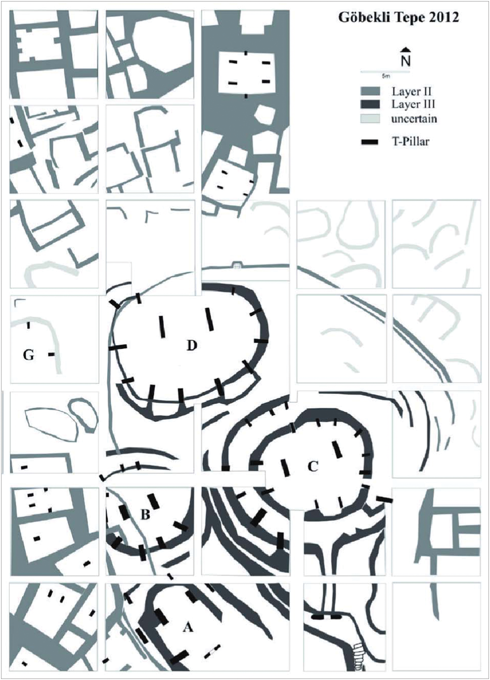
Four Layer III enclosures (Enclosures A–D) were uncovered so far in the main excavation area, each featuring a number of often decorated monolithic T-shaped stone pillars (3–4 m high) embedded into stepped-back peripheral walls and set around a pair of central larger stone pillars (up to 5.5 m high). The lower part of the peripheral walls (the ‘bench’) typically interconnects the inner edges of the T-shaped pillars. In their final form, structures B, C and D were curvilinear enclosures (10–30 m in diameter), possibly partially subterranean and roofed (L. Dietrich et al. Reference Dietrich, Meister, Dietrich, Notroff, Kiep, Heeb, Beuger and Schütt2019 and references therein), each defined by one or more circumventing peripheral walls (which may also represent different construction episodes). Enclosure A (which based on radiocarbon dating is assumed to be the most recent one)Footnote 1 is characterized by elongated walls. It has been suggested that Enclosure A may represent a transitional phase from round to rectangular architecture (O. Dietrich Reference Dietrich2017a; O. Dietrich et al. Reference Dietrich, Köksal-Schmidt, Notroff and Schmidt2013).
One of the most outstanding characteristics of the site is the richness in imagery items (especially) associated with the megalithic architecture. Many of the architectural elements including pillars, pillar bases, port-holes and gates bear representations in relief, depicting a wide range of wild animals. Mostly, the monolithic T-shaped pillars bear representations in bas-relief, but high-relief representations and smaller 3D sculptures integrated in the walls have been found as well (Schmidt Reference Schmidt2006; Reference Schmidt2007; Reference Schmidt2008; Reference Schmidt2010; Reference Schmidt2012). Of the Layer III T-shaped stone pillars, the two central pillars of enclosure D stand out, as they depict anthropomorphic ‘beings’, with the head represented by the traverse top of the T-shape, while the body is represented by the vertical part of the pillar (‘shaft’) on which orthogonal projections of arms, hands, belt and a possible so-called groin cloth are depicted on three sides (Pillars 18, 31). Similar anthropomorphic T-shaped pillars, although smaller, were first excavated in the cultic terrazzo building of the Early Pre-Pottery Neolithic B (EPPNB) site of Nevali Çori (Hauptmann Reference Hauptmann, Frangipane, Hauptmann, Liverani, Mathhiae and Mellink1993). In Göbekli Tepe, too, the T-shaped pillar tradition continued into the PPNB although the T-shaped pillars featuring in the PPNB rectangular structures (Layer II) are much smaller (about 1.5 m high, similar to the Nevali Çori pillars) and less frequently decorated. Small-sized T-shaped monoliths are also known from several Pre-Pottery Neolithic (PPN) sites in the Şanlıurfa region, around Göbekli Tepe (e.g. Sefer Tepe, Karahan Tepe and Hamzan Tepe) (Çelik Reference Çelik2010; Reference Çelik2011; Güler et al. Reference Güler, Çelik and Güler2013). However, while the depictions carved on the pillars seem to have been shared across a wide territory, the pillars themselves (the platform) were more limited in distribution. For example, the snake with a triangular head is a common motif both in Göbekli Tepe and PPNA Jerf el Ahmar (Helmer et al. Reference Helmer, Gourichon and Stordeur2004).
Other than the megaliths, construction technology included rock-hewn and lime-plaster (‘terrazzo’) floors, walls built of dressed stones (sometimes worked on all sides) in both the external and internal faces with a core of earth and smaller stones in between, and the use of mud mortar and wall plastering (preserved in Enclosure D).
A brief description of the enclosures
Enclosure B
Enclosure B was not fully excavated. Its western part is still superimposed by PPNB structures. The peripheral wall (about 9 m in diameter) surrounding the two central pillars includes nine T-shaped pillars so far. The top of walls exposed north and south of the peripheral wall may suggest a second concentric wall (about 14 m in diameter), so far without pillars. The enclosure seems to have had a lime-plastered floor, which was exposed mainly between the two central pillars. By the eastern central pillar, a stone slab with a shallow channel leading to a carved bowl embedded in the floor hints, according to the excavator, that a ritual may have taken place in the space between the twin pillars (O. Dietrich et al. Reference Dietrich, Köksal-Schmidt, Notroff, Schmidt and Kürkçüoğlu2012a; Schmidt Reference Schmidt2001), both bearing bas-reliefs of a south-facing fox on their inner side. According to the research team, the lime-plaster floor may cover an older bedrock floor similar to the floors in Enclosures C and D (O. Dietrich Reference Dietrich2017b). The setting of a number of the T-shaped peripheral pillars bearing reliefs on their narrow rear side (away from the centre) (Peters & Schmidt Reference Peters and Schmidt2004) may indicate that they are re-used. A rectangular port-hole stone was found in the backfill material at the centre of the enclosure, south of the central pillars. Another port-hole, found in situ embedded in a wall (O. Dietrich Reference Dietrich2017b) north of the first peripheral wall, seems to align with the axis of symmetry that runs between the central pillars of this enclosure.
Enclosure C
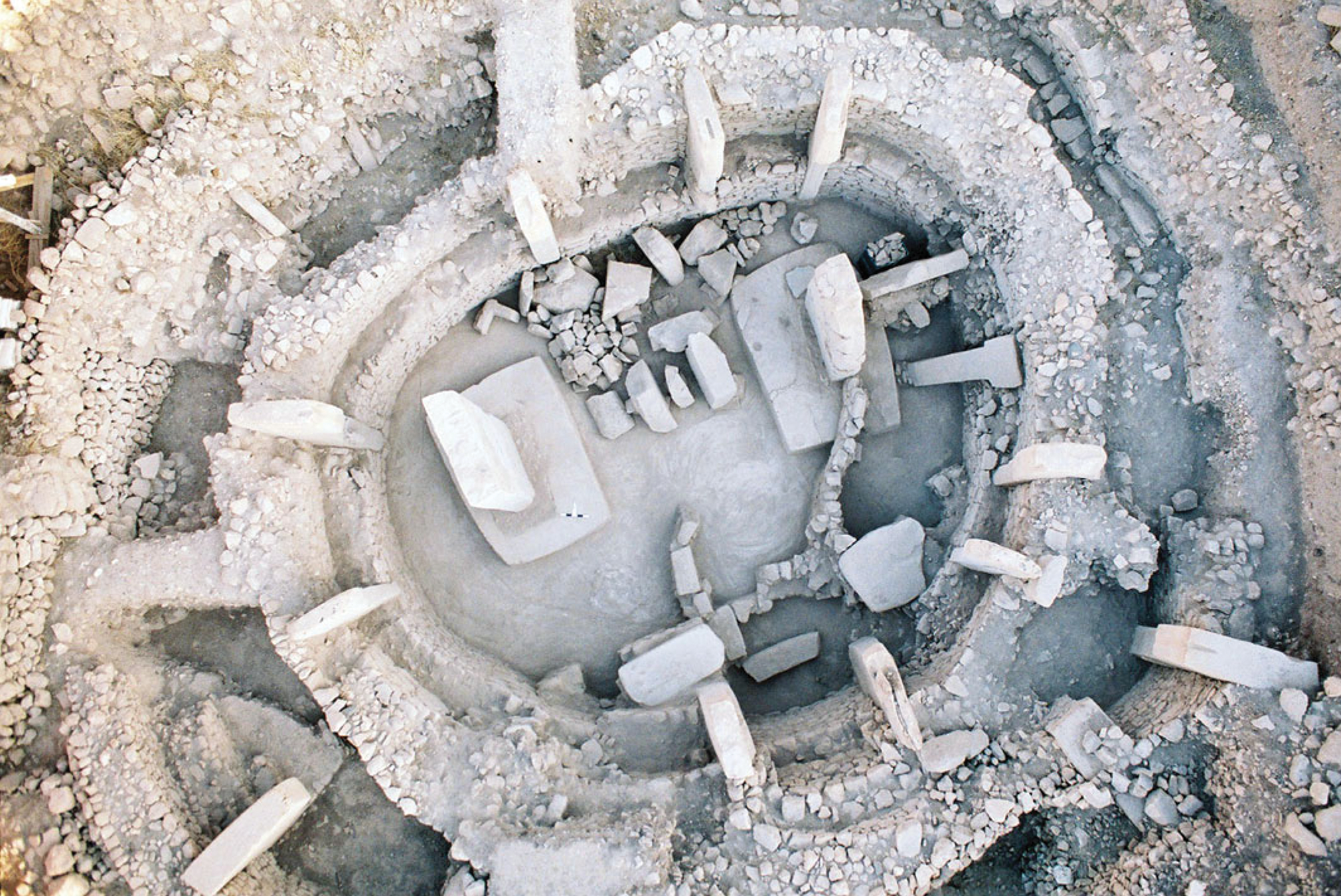
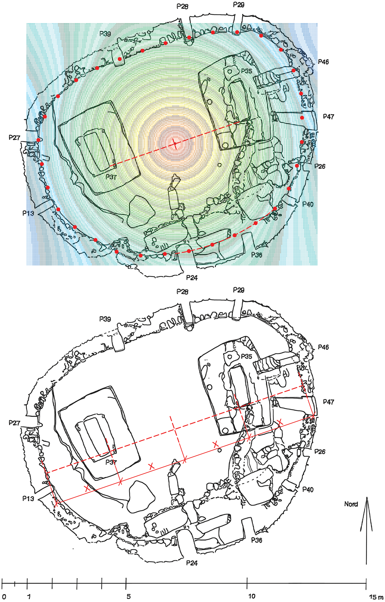
The remains of Enclosure C comprise at least two concentric peripheral walls (possibly three, according to Piesker Reference Piesker2014). The inner wall (about 11 m maximum interior diameter) has been completely exposed. It includes a peripheral bench-like inner lower part which connects the edges of the 11 peripheral T-shaped pillars. The ‘bench’ follows a continuous oval curve which is disrupted between the two southern pillars forming a niche or an entrance that was successively blocked. The ‘bench’ (up to 1.6 m high above the bedrock floor) was not found capped with stone slabs (as for example in Enclosure F, west of the main excavation area). Instead, stone slabs (possibly recycled T-shaped pillars) were found in front and to the sides of the southern peripheral pillars, resting on additional bench-like or platform features running parallel to the long side of the rectangular space between the central pillars. The floor of the enclosure is a carefully levelled bedrock surface which includes two rock-hewn platform-like pillar bases for the ‘twin’ central pillars. Interestingly, the pillars are not centred on their bases but set closer to the peripheral walls, leaving a larger platform surfaces towards the centre (Fig. 2). That part of the eastern pillar base features two circular depressions, and on top of it, a sculpture of a boar and ground stone implements have been found (O. Dietrich et al. Reference Dietrich, Heun, Notroff, Schmidt and Zarnkow2012b, fig. 6; Schmidt Reference Schmidt2008). The peripheral T-shaped pillars of the inner peripheral wall (sometimes broken and mostly re-used) were integrated in built ‘pockets’ at different elevations within the wall to achieve a common top elevation. According to Piesker (Reference Piesker2014), the construction seams, usually placed on both sides of the peripheral T-shaped pillars, indicate that the inner peripheral wall was built in its entirety in a single construction episode, leaving sockets in the wall for the later installation of the pillars (with the exception of the blocking of the southern entrance and the installation pillar P40 that was identified as a later addition). The second peripheral wall (with an inner diameter of about 17 m) features eight pillars so far. Its northeastern part has only been partially excavated. In the southwestern part of the structure, a lime-plaster floor was preserved in the passageway between the two peripheral walls at an elevation of about 2.1 m above the central bedrock floor. At its southern part, the second peripheral wall connects to an elongated passageway (‘dromos’) which leads from a gate complex that includes a port-hole stone and a decorated monolithic U-stone (Schmidt Reference Schmidt2012, 124, 148–9). According to the excavator, sometime in antiquity, a large robber pit (10 m diameter and 3 m deep) had been dug at the centre of the enclosure penetrating the backfill, in what looks like a deliberate action against the buried central pillars, whose broken parts were found on the pit's floor (Schmidt Reference Schmidt2008). The western central pillar bears a bas-relief of a fox. The inner face of the eastern pillar was badly damaged, but according to the excavator the remains of a bull depiction are still visible. Enclosure C is rich in decorated pillars: most notable is Pillar 27 that bears a high relief of a predator on its narrow inner face (Schmidt Reference Schmidt2006).
Enclosure C. Note the discontinuity of the bench between the southern pillars and the additional construction built against the southern part of the inner peripheral wall. (Reproduced from O. Dietrich et al. Reference Dietrich, Heun, Notroff, Schmidt and Zarnkow2012b.)
Enclosure D
Enclosure D has been described as the largest and best preserved of the Layer III enclosures in the main excavation area (e.g. O. Dietrich et al. Reference Dietrich, Köksal-Schmidt, Notroff, Schmidt and Kürkçüoğlu2012a; Notroff et al. Reference Notroff, Dietrich, Schmidt and Osborne2014; Schmidt Reference Schmidt2012). It also has the most symmetrical (oval shape) contour and pillar arrangement. The maximum inner diameter of this enclosure is about 14 m. Its peripheral wall, preserved to an elevation of over 3 m, connects (so far) 11 T-shaped pillars, some of which are decorated with complex depictions. Its central pillars with anthropomorphic depictions, rising to a height of 5.5 m, are the largest megalithic features on the site. As in Enclosure C, the twin central pillars were set on shallow pedestals or platform-like bases (20–30 cm high) carved out of the bedrock forming the enclosure floor. The southern face of the eastern pillar base is decorated with bas-relief. The twin central pillars are facing south, and one of them (the eastern) has a bas-relief of a fox on its inner side (as in Enclosures B and C), depicted above the arm as if it is being carried by the anthropomorphic being (Schmidt Reference Schmidt2007). In the southern part of the enclosure, the remains of a second peripheral wall have been exposed, although this wall is built differently than the outer peripheral wall of Enclosure C, as it is more segmented and includes protruding straight walls which connect to the narrow rear side of the peripheral pillars, dividing the space between the concentric walls into cell-like enclosures. It has been suggested that those radial wall segments were meant to counter the thrust of roof beams (Banning Reference Banning2011).
Enclosure A
Enclosure A is only partially excavated, and although its floor has not yet been reached, its floor plan already seems different than the other Layer III enclosures. Unlike the radial arrangement of the peripheral pillars in Enclosures B–D, the four peripheral T-shaped pillars exposed so far in Enclosure A are all oriented parallel or perpendicular to the direction of the central pillars. The central pillars are not free-standing as in the other enclosures, but attached to straight wall segments that extend towards the south and connect by an apse-like curved wall on their northern side. According to the Göbekli Tepe Research Team, the eastern central pillar (P2) does not stand in its original position, since in addition to other field observations, it bears reliefs on its narrow, northern side. Radiocarbon dates have confirmed the excavator's hypothesis that this enclosure is younger than Enclosure D (O. Dietrich et al. Reference Dietrich, Köksal-Schmidt, Notroff and Schmidt2013, and see note 1).
Architectural formal analysis
So far, very little has been written about the construction history of the Layer III enclosures (but see Clare et al. Reference Clare, Dietrich, Notroff, Sönmez and Hodder2018; O. Dietrich et al. Reference Dietrich, Köksal-Schmidt, Notroff and Schmidt2013; Piesker Reference Piesker2014) which remain a primary topic of investigation (Notroff et al. Reference Notroff, Dietrich, Schmidt and Osborne2014). It has been suggested that remodelling phases consisted of building a peripheral wall of smaller diameter, which was set inside larger, earlier versions of the enclosures (e.g. L. Dietrich et al. Reference Dietrich, Meister, Dietrich, Notroff, Kiep, Heeb, Beuger and Schütt2019; Hodder in Banning Reference Banning2011; Schmidt Reference Schmidt2012; Watkins Reference Watkins2004).Footnote 2 It has also been suggested that at the end of the use life of each enclosure, it was filled and a new enclosure was built alongside (Watkins Reference Watkins2010), or more specifically, that based on somewhat younger 14C dates, the outer peripheral wall of Enclosure C may have been built during the backfilling of Enclosure D (O. Dietrich et al. Reference Dietrich, Köksal-Schmidt, Notroff and Schmidt2013). According to the excavator, this remained an open question, admitting that it is possible that the Layer III enclosures date from the same time, while it is also possible that they were built in succession (Schmidt Reference Schmidt2012, 215).
The following architectural formal analysis is an attempt to shed some light on the chronological relations between and within the enclosures by a reconstruction of certain aspects of their initial design process, which further nuances the chaîne opératoire of their construction, especially the early stages of planning and laying out the plan on the ground. This will be achieved by identifying the spatial principles and compositional laws governing the generation of the structures’ form.
Methodology
Architectural formal analysis, which studies the spatial forms of architectural built spaces, is used to trace back aspects of architectural planning processes, construction and performance. Such analysis may indicate, for example, the use of a pre-planned schema and its adaptation to a specific site, or highlight the internal logic that guided the architectural design process. In order to detect spatial relations that may not be noticeable at first glance, we use an analytic tool (an algorithm) based on standard deviation mapping to study spatial form and relative location of architectural features in space. The algorithm, which we have previously used to analyse Natufian structures (Haklay & Gopher Reference Haklay and Gopher2015), produces a statistical centre point based on the relative position of architectural elements. In a second phase of the analysis, the mathematically identified centre point is examined in relation to the whole assemblage of architectural remains (other non-tested features), in order to find out if it may suggest a geometric regularity or indicate a point of significance.
The standard deviation mapping method consists of a simple geometric and statistical calculation carried out by an algorithm. The input for the algorithm is co-ordinates (relative to an arbitrary origin) of physical points in space. For example, the points may mark the centres of post-holes or trace the path of a wall. A grid (e.g. 5 cm spacing) is first superimposed over a plan of the architectural remains, and the algorithm proceeds by measuring the group of distances from each grid point to the set of input co-ordinates. Mean and standard deviation values are calculated for each group. The output is a statistical centre point in which the group of distances to the given input points has the lowest standard deviation value. Thus, relative to that centre point, the dispersion of the group of distances is minimal (it equals zero if the points all lie on a circumference of a circle).
Since the excavation is on-going and an updated detailed plan has not yet been published, we have used the most up-to-date schematic plan available which proved sufficient for the purpose of our analysis. In addition, we used the detailed plan of Enclosure C following Piesker (Reference Piesker2014).
Results
Analysis—phase A
We first examined Enclosures B, C and D that share a basic layout which can be described in the most abstract way as a pair of central pillars, surrounded by peripheral pillars embedded in a curved wall. In order to articulate this common layout further, we searched for a regularity in the position of the central pillars within the enclosures. We used standard deviation mapping to detect statistical centre points within the enclosures, based on the relative (and final) location of the peripheral pillars embedded in the inner ring walls. Each pillar was represented by a point marking its approximate centre (these points best represent the location of the pillars regardless of their orientation), and in each enclosure, the centre point identified was the point at which the standard deviation value of the group of distances (from that point) to the points marking the peripheral pillars was minimal (Fig. 3).
Architectural formal analysis: Phase A. Identification of a geometric and statistical centre point based on the locations of the peripheral pillars: visualization of the calculation. Note the red dots marking the peripheral pillars and the resulting centre points. (Drawing superimposed over the schematic plan. Modified from O. Dietrich et al. Reference Dietrich, Köksal-Schmidt, Notroff and Schmidt2014.)
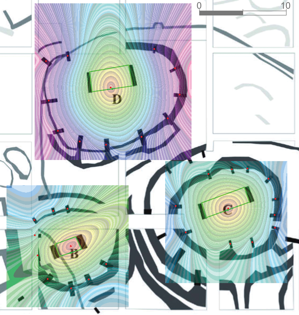
The centre points in Enclosures C and D were found to be at the middle point of the southern edge of the quadrilateral space between the central pillars (aligned with the front of the south-facing anthropomorphic T-shaped pillars), while in Enclosure B it was near the centre of that space. These results suggest that there is an exact geometric relation between the central and the peripheral pillars.
It is of note that the central pillars in Enclosures C and D were set into pedestal-like bases carved in bedrock, which most probably pertains to the initial construction of the enclosures, while the central pillars of Enclosure B are set in a plaster floor. Unlike the central pillars, the peripheral pillars and walls may have been subjected to modifications during the life history of the enclosures. Yet each time a peripheral feature was altered or added, it was nevertheless carried out with reference (and full awareness) in the mind of the builders to a point in space that marked the centre of attention in each enclosure—the centre point. Although the exact construction sequences of the enclosures are mostly unknown, the same geometric rules seem to have been referenced in both the original construction and subsequent alteration episodes.
In the case of Enclosure C, whose central floor was completely exposed, we were able to verify the identification of the centre point also with respect to the curvature of the peripheral wall. We marked on the detailed plan 32 evenly spaced points (at intervals of 1 m) along the curve describing the inner face of the peripheral wall (continuing the curve over the southern niche/opening where the bench is missing to achieve a continuous contour) (Fig 4). We applied the standard deviation mapping algorithm with relation to these 32 points and verified that the centre point indeed results exactly at the midpoint between the southern faces of the central pillars. In addition, we noticed that along that axis the distance between the centre point and the inner faces of the central pillars (about 2.8 m) is equal to the distances from the inner faces of the central pillars to the inner face of the peripheral wall (Fig. 4).
Architectural formal analysis: Phase A. (Top) Identification of a geometric and statistic centre point based on the curvature of the inner peripheral wall: visualization of the calculation. Note the red dots marking 32 points along the inner face of the wall and the resulting centre point. (Bottom) The central pillars and peripheral wall are equidistant from each other along the main axis. (Drawing superimposed over the detailed plan. Redrawn from Piesker Reference Piesker2014, fig. 8.)
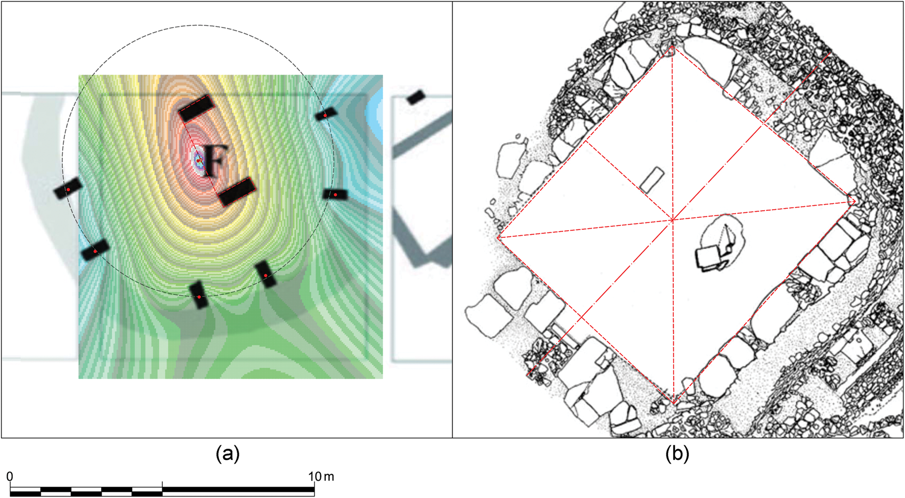
Further verification that the central pillars are precisely positioned within the enclosures (as in Enclosures C and D) is provided by Enclosure F, west of the main excavation area. We used the same standard deviation mapping (algorithm) to detect a statistical centre point which similarly resulted in a point between the central pillars, aligned with their southwestern extremities (Fig. 5a). Finally, it seems that the same abstract rule was followed also in the PPNB cult building at Nevali Çori. There, a pair of anthropomorphic T-shaped pillars was set within a rectangular floor defined by peripheral pillars and bench, and, as was the case at Göbekli Tepe, it is the edge, not the centre, of the central pillars that aligns with the main axis of the structure (Fig. 5b). The example of Nevali Çori suggests that, along with the tradition of having two central anthropomorphic T-shaped pillars, the design rule regarding their positioning may have persisted as well.
(a) Göbekli Tepe Enclosure F (modified from O. Dietrich et al. Reference Dietrich, Köksal-Schmidt, Notroff and Schmidt2014); (b) Nevali Çori.
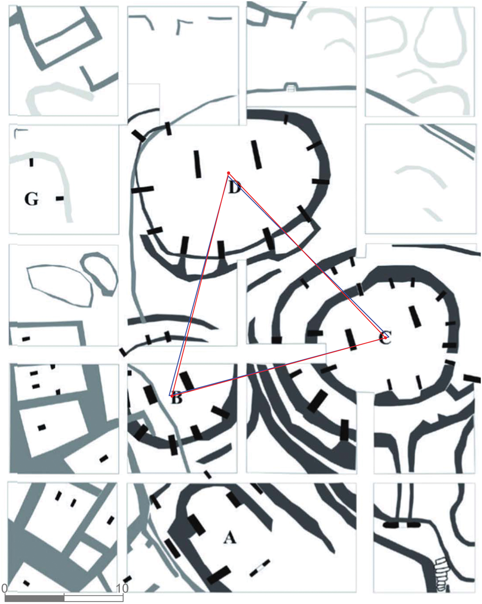
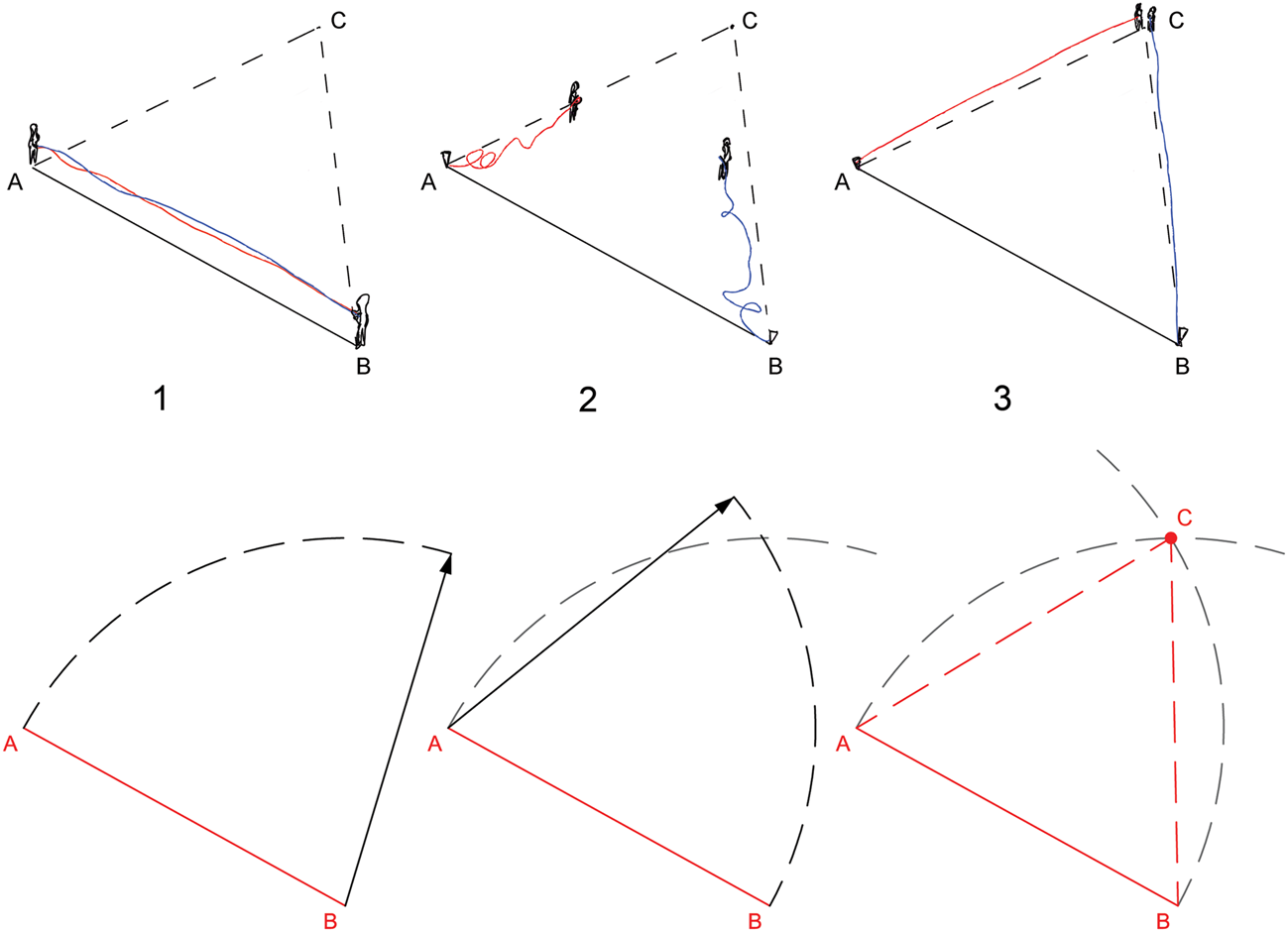
Once this design rule that regulated the positioning of T-shaped pillars at Göbekli Tepe Layer III was identified, we focused our attention on a specific location in each enclosure, i.e. the middle point between the front narrow sides of the central pillars—a point in space that has the spatial role of geometrically tying together the central and the surrounding peripheral pillars. In the main excavation area in Göbekli Tepe, the spatial role of these points may have been extended beyond the boundaries of the single enclosures, as these points in Enclosures B, C and D form an almost perfect geometric pattern too, being only 25–28 cm distant from the vertices of an ideal equilateral triangle with a side length of about 19.25 m (Fig. 6). This precision with a distortion of less than 1.5 per cent is less likely to be coincidental, nor the result of a self-organization process. This basic geometric shape (the equilateral triangle) could have been measured simply by stretching a rope of the desired triangle side length to mark the first two vertices of the triangle and then finding the third vertex in the meeting point of two stretched ropes of that same length pegged in the first two points (this is further discussed below; and see Figure 8).
Architectural formal analysis: Phase A. (In red) The triangle defined by the three middle points between the southern faces of the central pillars; (In blue) An equilateral triangle. (Drawing superimposed over the schematic plan. Modified from O. Dietrich et al. Reference Dietrich, Köksal-Schmidt, Notroff and Schmidt2014.)
Analysis—phase B
We further analysed the remains of the three enclosures in order to find out if the possible underlying pattern may refer to additional properties of these structures and other features on site. We noticed that the equilateral triangular pattern highlights the alignment of the central pillars of Enclosures B and C, along an axis parallel to its southern side (Fig. 7). Furthermore, the composition and orientation of the central pillars implies an axis of symmetry. We found that the two Layer III U-stone gates marked on the schematic plan are symmetrically located and oriented on both sides of that axis (Fig. 7), which may further support this claim (although the western U-stone's relation to other architectural features has not been clarified). The eastern U-stone is found at the end of an elongated passageway which connects on its other side to the second peripheral wall of Enclosure C. The passageway was built of large stones shaped on all sides (O. Dietrich et al. Reference Dietrich, Köksal-Schmidt, Notroff and Schmidt2014), and along with the 3×3 m U-stone monolith, they constitute a massive construction, which is likely to have been included in the initial (planning and) construction of the enclosure. It is possible that a similar passageway that led from the western U-stone to Enclosure B was cancelled by the successive (see note 1) construction of Enclosure A.
Architectural formal analysis: Phase B. (In red) The nearly equilateral triangle that passes through the middle points between the southern face of the central pillars of Enclosures B–D. (In yellow) The alignment of the central pillars of Enclosures B and C along the southern triangle side. (In blue) The main axis, perpendicular to the southern triangle side, passes through the centre of Enclosure D. (In green) The U-stones symmetrically positioned on both sides of the main axis. (Drawing superimposed over the schematic plan. Modified from O. Dietrich et al. Reference Dietrich, Köksal-Schmidt, Notroff and Schmidt2014.)
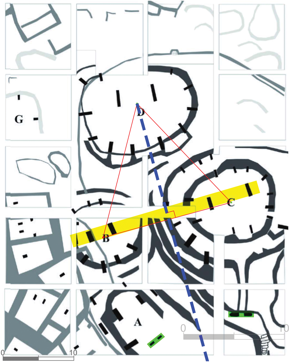
The axis of symmetry also implies a certain architectural hierarchy, suggesting a special significance to Enclosure D. This hierarchal organization of space is not only confirmed by the size of Enclosure D and the height of its central pillars, but most possibly also by the fact that the central pillars of Enclosure D are the ones bearing anthropomorphic attributes. The fox depiction that decorates the central pillars of Enclosures B and C appears also on a central pillar of Enclosure D, but there it is accompanied and dwarfed by the anthropomorphic depictions. Enclosure D has also been singled out by the excavator as the only enclosure that includes depictions of all the main game animals (gazelle, Asiatic wild ass, wild sheep and aurochs) and thus correlates with the faunal assemblage (Peters & Schmidt Reference Peters and Schmidt2004, 209). We therefore suggest that, despite the numerous construction episodes and the continuous remodelling of the enclosures, it can be stated that the three enclosures B, C and D were planned and initially built as a complex. This does not necessarily mean that they were built simultaneously, but this possibility raises the question of whether the initial construction of all three enclosures was more permeable, allowing lines of sight between their centres. As noted by Piesker (Reference Piesker2014) and Clare et al. (Reference Clare, Dietrich, Notroff, Sönmez and Hodder2018), the peripheral T-shaped pillars embedded in the inner stepped peripheral wall of Enclosure C (which may represent a later construction phase) were never free-standing, since they rest on the peripheral wall at different elevations and were mostly installed in built pockets in the wall. However, less is known about the pillars of the outer peripheral wall of this enclosure. Piesker suggested that, due to the large size of the southern pillars (P11, P12, P23, PMA), they most probably rest on bedrock, and that the northern P25 may be installed in a rock-hewn pedestal base similar to the central pillars, so the issue of sight lines between the centres of the enclosures remains a possibility to consider.
In summary, we used standard deviation mapping to detect statistical centre points within the round Enclosures B–D, based on the relative (and final) locations of the peripheral pillars embedded in their inner peripheral walls. We found that these centre points coincide in enclosures C and D with the middle points between the southern narrow sides of the central pillars. This seems to be a design rule that determined the exact location of the central pillars within the enclosures. The identification of this general pre-planning rule was confirmed by the examination the remains of Enclosure F in Göbekli Tepe and the remains of the PPNB cult building at Nevali Çori, in which, similarly, the middle point between the front faces of the twin central pillars is set in accordance with the (geometric and statistic) centres of the floor in which they are installed. We further noticed that these three points in Enclosures B–D at Göbekli Tepe form a rather exact equilateral triangle. The geometric pattern was confirmed when examined along with the orientation of the central pillars (not yet taken into account in our analysis), as the central pillars of Enclosures B and C align along an axis marked by the southern side of the equilateral triangle. Further confirmation is possibly offered by the symmetric position of the in situ U-stones on both sides of the main axis (perpendicular to the southern edge of the equilateral triangle passing through the centre of Enclosure D). In our opinion, these findings provide strong support to our conclusion that Enclosures B–D originated as a single project.
Discussion
The implications of the above analysis and its results concern a number of issues and interpretations discussed by Göbekli Tepe investigators over the years to which our results may add some insights.
1: A possible hierarchy between and within the enclosures
Our analysis revealed a clear hierarchically structured space. The suggestions we made here, that Enclosures B, C and D are one complex, highlight the higher hierarchical position of Enclosure D, which includes the axis of symmetry of the complex as a whole. Hierarchy is also implied at the intra-enclosure level considering the fact that the peripheral pillars are arranged around a centre point between the fronts of the two central pillars—a design rule that defines a precise spatial hierarchical relationship between central and peripheral elements (pillars). We may add the fact that the large central pillars of Enclosure D, at the top of the hierarchical order, are singled out as a unique class in the B–D enclosures complex as a whole by their anthropomorphic depictions and prominent appearance. The overlying symbolic layer, that is the depictions on the pillars, further refines the hierarchy represented by the architectural design.
2: The level of organization and manpower required
The level of organization and manpower required for the construction of the megalithic architecture of Göbekli Tepe (e.g. Bar-Yosef Reference Bar-Yosef, Finlayson and Makarewicz2014; Notroff et al. Reference Notroff, Dietrich, Schmidt and Osborne2014) should be multiplied by three, compared to previous estimations, if our suggestion is simply accepted, since the potential size of a single project at Göbekli Tepe comprised three enclosures in the case presented here. Even if this suggestion is reserved, and beyond planning only the initial stages of construction were contemporaneous, this further amplifies the factors of manpower, organizational aspects, pace of construction and more.
3: Was each enclosure constructed independently or not?
The suggestions based on the assumption that the structures were built and functioned independently, either as residential units as suggested by Banning (Reference Banning2011), or as public structures used by different (possibly competing) social groups as suggested by Schmidt (Reference Schmidt2000) and others (Peters & Schmidt Reference Peters and Schmidt2004; Notroff et al. Reference Notroff, Dietrich, Schmidt and Osborne2014), seem less likely (at least in the planning phase as well as at the beginning of their lives) following the results presented in this paper. The suggestion regarding the different identities of the builders of each enclosure, which accords well with Schmidt's early impression of the site as a ritual centre that drew people from as far as Jerf el Ahmar and Nemrik (Schmidt Reference Schmidt2002b), was further supported by the identification of dominant animal species depictions in each enclosure, and their interpretation as emblems of different groups (although as long as the central pillars are considered, the depictions may express a linkage rather than differentiation between the enclosures, as the symbol of the fox appears in every pair). Schmidt rightly noted that the depicted reliefs are reproduced in the different enclosures with an accuracy that could only be the work of a school of specialists, and attempted to settle this fact by suggesting that the enclosures may have only been ‘ordered’ by the different social groups (Schmidt Reference Schmidt2008). Our suggestion for a new understanding of the architectural remains of Enclosures B–D as constituting a complex (initially planned as a single project) makes it less likely that the different enclosures were initially built or commissioned by different peoples/groups (Notroff et al. Reference Notroff, Dietrich, Schmidt and Osborne2014; Peters & Schmidt Reference Peters and Schmidt2004), and it does not support the suggestion that one enclosure was being built while another was being (or already was) covered up.
No less important, and central to this paper, is the issue of architectural planning and the practical stage of laying out a construction project on the ground. It has been suggested that wild flax fibre ropes were used to measure the straight outlines on the T-shaped pillars (Bar-Yosef Reference Bar-Yosef, Finlayson and Makarewicz2014). It is possible that ropes may also have been used to position the central pillars of Enclosures B–D according to an architectural plan. The discerned geometric regularities attest to an understanding of certain geometric principles and their creative employment in the architectural design process. While the actual measuring of an equilateral triangle may not in itself be a difficult task, it represents an attempt to produce a shape accurately by identifying intersection points of curves traced by compass-arm techniques, which is an archaic form of a (‘Euclidian’) geometric construction (Fig. 8). The use of geometric construction in architectural planning enabled the planner to conceptualize a proportional abstraction of a floor plan of a rather complex design, and to reproduce it at any size. While the relatively simple architectural plans conceptualized in the preceding late Epipaleolithic Natufian may have been mental ‘cognitive plans’ (Haklay & Gopher Reference Haklay and Gopher2015), during the PPNA, the dramatic increase in complexity of the architectural design must have required the formulation of a schematic (diagrammatic) small-scale floor plan which consisted of a pattern, geometrically constructed and regulated by a length module (and see Haklay & Gopher Reference Haklay and Gopher2019 for a measure of unit used at Çayönü in the PPNB). The concept of a floor plan as an external planning device is probably the biggest step forward in Neolithic architectural planning.
(Top) The laying-out of an equilateral triangle. The equilateral triangle could have been laid out by following a simple method: 1. Marking the first two vertices of the equilateral triangle (points A and B) by stretching a cord of the desired triangle side; 2. Pegging two cords of the same length (the desired triangle side length) at points A and B; 3. Stretching the cords until their other ends meet at the point marking the third equilateral triangle vertex. (Bottom) Geometric construction of an equilateral triangle.
4: The nature of the T-shaped pillars
A detailed discussion on interpreting the Göbekli Tepe T-shaped pillars is beyond our scope here. We will concentrate on a few aspects regarding hierarchy and totemism.
It has been suggested in early interpretations of the Göbekli Tepe scene that the central T-shaped pillars of Enclosure D represent anthropomorphic ‘beings’ such as ancestors (e.g. Peters & Schmidt Reference Peters and Schmidt2004, 215). A similar suggestion was made for the other enclosures and it was also extended to the peripheral T-shaped pillars. The entity represented by a pillar bearing animal depictions is therefore a combination of a human (maybe an ancestor) and one or more animals. Simulating possible interpretations for the T-shaped pillars and the animals depicted on them, Peters and Schmidt (Reference Peters and Schmidt2004) discussed totemism as a possible interpretation for the animal depictions. In this framework specific relationships between man and animals are central. For example, the totem is often seen as a protector and in return the totemic animal is protected by a taboo forbidding its hunting.Footnote 3 Peters and Schmidt (Reference Peters and Schmidt2004) suggested that the pillars at Göbekli Tepe could also be interpreted as poles linking the underworld with the ‘living’ world. Following this line of thought, the T-shaped pillars may reflect both totemic entities and ancestors, as if the spirit of dead ancestors may operate in the world of the living through totem animals. It is possible that the identity of the T-shaped pillars may have been conveyed both by their 3D form as ancestors and by the 2D depictions they bear as animal forms that the ancestors may take in the world of the living. Considering our suggestion vis à vis the hierarchy of the enclosures and relating it to the depictions on pillars, we noted two elements:
1. The depictions of the central pillars of Enclosure D (the highest hierarchy) are unique in their clear anthropomorphic aspect (depicted on the entire pillar shaft on three sides), and in size, which is by no means the largest.
2. Fox depictions appear in every pair of central pillars. In Enclosures B and C, a single fox is depicted, and in Enclosure D it appears on the inner face of the central pillar at the height of the elbow of the depicted human arm. Schmidt suggested (Reference Schmidt2010, 244) that the figure ‘holds a fox in the crook of its elbow’. In addition, following Schmidt (Reference Schmidt2010) a fox-pelt was recognized (by its long tail) in the depicted loincloth worn by the anthropomorphic figures. Depictions of foxes on peripheral pillars are rare in Enclosures C and B and are common in Enclosure D.
The first observation confirms the discerned spatial hierarchy of the D, C, B complex, while the second observation suggests that the fox must have been of greater importance than other totemic animals,3 but its status in Enclosure D seems to have been different.
Under this interpretation of the T-shaped pillars as totemic ancestral beings, in Enclosures B and C (of the lower hierarchy) the fox (featuring on the central pillars of both enclosures) was the main totemic animal (and see note 3). Enclosure D, however, is different in two respects: first, the depictions on the central pillars suggest that the ancestors may take (in the world of the living) a human rather than a non-human animal form (which may be viewed as a sort of reincarnation); and second, the depictions on the peripheral pillars (in this enclosure only) include game animals that comprised most of the basic meat consumed by the occupants (gazelle, Asiatic wild ass, wild sheep and aurochs) (Peters & Schmidt Reference Peters and Schmidt2004), and may thus reflect a different relationship between humans and animals. Considering that the spatial arrangement of the structures, as we suggested, places Enclosure D at a higher order with respect to Enclosures C and B, the complex as a whole can be interpreted as reflecting a discourse related to dynamics of change in social order. We may speculate here and say that this hierarchy represents a new world order, or the beginnings of social differentiation reflected in the dead ancestors (or a dead ancestor) that are seen in the pillar itself and/or the depictions on it. This may have had significant repercussions in both the struggle over property (heredity order) and, most importantly, as the setting (incubation) of future domestications as seen in the redefined relationships between man and certain animals.
The discerned architectural hierarchy of the enclosures and the T-shaped pillars suggests that the people of Gobekli Tepe were well acquainted with the concept of hierarchy. This accords well with statements made by Özdoğan (Reference Özdoğan, Özdoğan and Basgelen1999; Reference Özdoğan, Manen, Perrin and Guilaine2014 and references therein) and by Schmidt (Reference Schmidt2012, 159) envisaging a rich, complex hunter-gatherer social system possibly characterized by dynamics of a growing inequality during the PPNA in the northern Levant. Benz and Bauer (Reference Benz and Bauer2013, 13, fig. 2) also view PPNA social developments as a result of a rise in inequality and a decrease in sharing. They suggest that it was possibly single human agents (shamans, for example) that took part in creating the new restless state of affairs and took advantage of it to ‘take over’ the ritual arena and socio-political power. This would work well with our interpretation above that the identity of the T-shaped pillars (of Enclosure D) may reflect a (newly introduced) concept of human-to-human reincarnation rather than totemic human–animal relationships.
Conclusion
Architectural formal analysis (and the central points calculated) has brought to light an underlying geometric pattern based on an equilateral triangle and a set of main perpendicular axes that ties together Enclosures B, C and D under a single, rather complex geometric design. This suggests a new understanding of what has been initially planned and then built in the enclosure's system of the main excavation area. It offers an answer to questions on the chronological relationships between the three enclosures, and it evokes insights regarding the architectural design process and how such architectural complexity could have been achieved.
Together with sites such as the PPNA Jericho in the southern Levant with its complex construction projects, Göbekli Tepe reflects a ‘foreign country’—a quantic jump of the latest hunters-gatherers in the region, a ‘wild growth’, a disorder of sorts in the hunting-gathering world, way beyond the capacity of a pristine hunter-gatherer society. This has eventually crystallized into new world-views, mainly in man–world and man–man relations that were subsequently translated into new lifeways and a new cultural landscape. The above attempt to incorporate our understanding of the outstanding architectural scene of Göbekli Tepe is only a beginning. The multitude of details that need analysis and understanding is still overwhelming, but we are sure that interpreting this site will continue and take new roads as the database grows and its analysis continues.
Acknowledgements
We thank Lee Clare and Oliver Dietrich for their permission to use and reproduce the figures in this paper. We thank the reviewers for their constructive comments.


 Open access