


1. Introduction
Additive Manufacturing (AM) technologies are continuously progressing. However, especially for Laser Powder Bed Fusion processes (PBF-LB/M) – the industry standard for metal AM – build volume restrictions remain one of the hinderances (Reference Goh, Wong, Tan, Seet and NaiGoh et al., 2024). While standard PBF-LB/M systems offer build volume of up to 500 mm per axis, special large-format systems push the boundaries beyond. Despite recent developments of PBF-LB/M systems with increasing build volume, one solution for overcoming this limitation is presented in combining part separation in AM with joining technologies (JT). JT are an integral part of established design philosophies, offering benefits beyond overcoming build volume restrictions and current Design for Additive Manufacturing (DfAM) guidelines. These include avoiding material accumulations to reduce thermal distortion and combining complex AM components with standardized components produced by conventional manufacturing (CM), enabling combined designs (Reference Reichwein, Rudolph, Geis and KirchnerReichwein et al., 2021). Moreover, part separation in AM combined with JT can reduce the effects of anisotropy and the need for support structures due to part orientation (Reference Oh, Zhou and BehdadOh et al., 2018). Consequently, two improvements can be achieved by part separation with subsequent joining in AM: manufacturability and functionality. While JT in AM are receiving significant research attention, most research focuses on fragmented aspects of individual JT in AM, such as the feasibility of JT for specific materials or improvements in joint strength (Reference Guzman, Riffel, Evans, Brizes, Avedissian, Farias and RamirezGuzman et al., 2025). However, decision-oriented frameworks that link AM-specific characteristics to JT selection and user needs remain limited. In CM multiple attempts have been made to aid designers in selecting suitable JT, yet none considers the specific challenges introduced by AM technologies. These challenges address potentials and restrictions of AM, such as cellular structures and build-induced anisotropy, which are less relevant in CM. To address AM-specific challenges regarding JT selection the following research questions are targeted:
-
• Which PBF-LB/M-specific potentials and restrictions influence the JT selection?
-
• How can these factors be integrated into a JT selection framework to support decision-making?
JT selection frameworks in CM and the potentials and restrictions of PBF-LB/M were analyzed to develop AM-adapted selection and evaluation criteria within a framework. This paper presents the framework development process and outlines the underlying criteria, data, and requirements that support decision-making in early design phases without the need of detailed joining geometry. Although research attention on JT in AM has increased, available data remain partly ambiguous or incomplete for certain criteria. For this reason, strength-related data were excluded from the framework, and structural verification must be conducted separately. The proposed framework represents a basis for systematic JT selection for PBF-LB/M components and may be further refined as additional data become available. This also applies to the combined joining of AM and CM components.
2. Foundations in joining technology selection and additive manufacturing
Joining is a fundamental aspect in CM, fulfilling functions such as load transfer, manufacturability, assembly, and interchangeability (Reference Bender and GerickeBender & Gericke, 2021). With the spread of AM, design thinking shifted toward component consolidation enabled by its layer-wise nature, allowing complex geometries that were infeasible in CM. (Reference Gibson, Rosen and StuckerGibson et al., 2015). Consequently, the importance of JT initially decreased in AM. However, as the technology matured, joining regained relevance due to remaining process restrictions. This section introduces existing approaches in CM for JT selection in Section 2.1 and design considerations concerning the role of joining in AM in Section 2.2.
2.1. Selection of joining technologies in conventional manufacturing
Selection strategies include information about requirements, the solution space and decision-making procedures (Reference Ashby, Bréchet, Cebon and SalvoAshby et al., 2004). As a result, establishing the foundation by deriving and collecting information about JT represents the starting point for selection processes. For this purpose, cross-JT criteria have been defined and further developed, such as material, thickness, quantity and permanence (Reference Booker and SwiftBooker & Swift, 1997; Reference SwiftSwift, 2013). Based on this knowledge, multiple approaches for JT selection have been developed to support designers in choosing suitable JT for CM processes.
In the approach of Reference LeBacq, Brechet, Shercliff, Jeggy and SalvoLeBacq et al. (2002), the selection process uses a predefined questionnaire as the selection basis. This questionnaire addresses joint design issues regarding geometry, material, function, and joining production conditions. The answers to the questionnaire are then compared to information on JT criteria in databases. As a first step of the fuzzy logic algorithm-based evaluation, technically incompatible solutions are excluded and documented in a list together with the reasons for their exclusion. In the second step, three types of evaluations are performed for the remaining JT, addressing compliance with the requirements, the company’s capability to handle the JT, and the acceptance of the solution within the industry. Additionally, an economic evaluation is conducted.
Another approach by Reference Brown, Swift and BookerBrown et al. (2002) expanded the JT criteria introduced by Reference Booker and SwiftBooker and Swift (1997), focusing on material, wall thickness, permanence, and production quantity of joints. Reference Brown, Swift and BookerBrown et al. (2002) further expanded the selection matrix introduced by Reference Booker and SwiftBooker and Swift (1997) based on these criteria and mapped JT to corresponding criteria. Additionally, they provide process information maps (PRIMAs) containing detailed information about JT. While the selection matrix reduces the number of feasible solutions, individual PRIMAs are provided for each JT to support subsequent decision-making. Reference SwiftSwift (2013) continuously refined the selection matrix and the PRIMAs. The (updated) PRIMAs further provided a foundation for subsequent JT research.
Another selection approach by Reference Esawi and AshbyEsawi and Ashby (2004) follows a procedure built around the elimination of unsuitable JT candidates. JT can be selected based on data regarding the criteria materials, material combination and geometry, and mode of loading. This data is used to eliminate JT. Subsequently, remaining technologies are ranked according to either equipment cost or production rate. Records of the highest ranked JT (similar to the PRIMAs of Reference SwiftSwift (2013)) are then examined, and promising technologies are matched with the resources of a company to support the decision-making.
Subsequent studies adapted the selection and evaluation approaches of the previously introduced works and refined the criteria for their specific use cases. In more recent approaches, a trend toward incorporating environmental, sustainability, and cost-related criteria can be observed (Reference Kaspar, Choudry and VielhaberKaspar et al., 2018). Furthermore, refinements of JT-related criteria are implemented, such as the Joint Complexity Index, which quantifies the complexity of the JT as an additional evaluation criterion (Reference Mesa, Illera, Esparragoza, Maury and GómezMesa et al., 2018).
Other studies adapted selection procedures to specific use cases by aligning them with manufacturing processes or by extending the evaluation approaches. For example, Reference Dawande, Kumar Das and Arun GadgeDawande et al. (2024) implemented a selection framework for plastic assembly within a tool using Artificial Intelligence, focusing on the possibility to import joint information from Computer Aided Design (CAD) models. Reference Saluja and SinghSaluja and Singh (2023) used a multi-criteria decision approach to evaluate JT based on technical, economical, service, and sustainability criteria after eliminating unsuitable JT. Reference Das and SwainDas and Swain (2022) developed an approach that integrates joint information extracted from CAD models with a knowledge-based system to identify suitable JT based on material compatibility, geometry, thickness, and joint requirements.
In summary, early studies established a common JT selection logic in CM: unsuitable JT are first eliminated, followed by evaluation and decision support of remaining alternatives. Later studies primarily refine criteria or adapt the method to specific applications rather than altering the selection logic. The next section discusses AM-specific features relevant to JT selection.
2.2. Additive manufacturing – design philosophies, potentials and restrictions
The emergence of AM fundamentally changed component design by enabling complex geometries and increased design freedom through layer-wise manufacturing. Designers exploited this capability through part consolidation, improving material utilization and combining multiple parts into a single component. This often coincides with the integration of different functions into one part, leading to the association of AM with the concept of integral design. Additional benefits include topology-optimized designs, the feasibility of cellular structures enabling further material savings, and local adaptations of material properties to achieve material grading. (Reference Bender and GerickeBender & Gericke, 2021; Reference Lachmayer, Ehlers and LippertLachmayer et al., 2024)
However, AM (and PBF-LB/M) still involves process-related restrictions such as surface quality, anisotropy, support structures and overhangs, thermal distortion, buckling, geometric deviation, post-processing, and porosity. Component size is limited by the build volume, especially in chamber-bound manufacturing processes such as PBF-LB/M. (Reference Gibson, Rosen and StuckerGibson et al., 2015; Reference Lachmayer, Ehlers and LippertLachmayer et al., 2024)
Some of these restrictions cannot be overcome by integral design and motivate the use of differential design and subsequent joining. Differential design contrasts with integral design, dividing a single part into multiple components. In general, separation and joining enable an improvement in performance, manufacturability or manufacturing costs. (Reference Bender and GerickeBender & Gericke, 2021)
Reference Oh, Zhou and BehdadOh et al. (2018) show that differential design can overcome several AM limitations, such as build volume restrictions. Manufacturing time, costs, and product quality can be improved by changing the orientation of the separated parts, which also affects mechanical performance due to AM-induced anisotropy. The same applies to surface quality, which can be improved by reducing inclined and curved surfaces or by minimizing the need for post-processing. Part separation and detachable joints also enhance flexibility and interchangeability. Reference Reichwein, Rudolph, Geis and KirchnerReichwein et al. (2021) suggest part separation and subsequent joining to avoid material accumulations and, consequently, thermal distortion. Additionally, the combination of AM and CM allows material conditions that would not be possibly by AM alone.
In conclusion, combining differential design and joining should be applied to improve the functionality. Overcoming manufacturing restrictions emphasizes the need for suitable JT and a selection framework to support designers in identifying appropriate solutions.
3. Framework development process
Based on the previous section, Section 3.1 analyzes JT selection approaches and criteria from CM for their adaptation to a JT selection framework for AM. Section 3.2 discusses AM-specific aspects and integrates them into the framework to extend the selection criteria.
3.1. Adaptation of established selection frameworks
In the first step, JT selection approaches were compared to deduce transferable guidelines and existing selection criteria that can be applied to the adapted framework. The procedure of the framework is illustrated in Figure 1, which also acknowledges the original authors who introduced the underlying approach in the field of JT selection. The symbols within Figure 1, and further flowcharts, are according to DIN 66001. The fundamentals are derived from Reference Brown, Swift and BookerBrown et al. (2002). They introduce a selection process centered around the exclusion of unsuitable JT based on questionnaires in the first place. In a subsequent step, more data about the remaining JT are provided to the user in the form of data sheets for manual evaluation based on their specific needs. This JT data provided by Reference SwiftSwift (2013) (updated version, founded by Reference Booker and SwiftBooker and Swift (1997)) built the foundational databases for later researches. Reference LeBacq, Brechet, Shercliff, Jeggy and SalvoLeBacq et al. (2002) and later authors followed this approach. Therefore, this approach, including selection and technical evaluation, will be adjusted for this study.
Simplified framework indicating the procedure and origin of the criteria

Reference LeBacq, Brechet, Shercliff, Jeggy and SalvoLeBacq et al. (2002) extended the evaluation by introducing criteria to verify the competence of a company to apply the proposed JT. These criteria relate to the capability and availability of tools required to perform the joining process. This competence evaluation is included in the framework as it provides added value with minimal implementation effort and remains optional for the user. Adjusting requirements when no JT meet the specified needs (as applied by Reference Kaspar, Choudry and VielhaberKaspar et al. (2018) and suggested by other authors) is adopted as an iterative step within the framework.
In the second step, existing and new evaluation criteria are classified regarding organizational conditions, part, functionality and process as illustrated in a simplified model in Figure 2. Different criteria are assigned to these four main categories. For each category, only the first layer is shown, while subsequent layers are implied by dashed lines. Moreover, the origin of each criterion, such as Design for Assembly (DfA) based on Reference Boothroyd, Dewhurst and KnightBoothroyd et al. (2011), is indicated by the background color to ensure traceability. In the following, the material category serves as an example to explain Figure 2 and subsequent layers implied within the figure. According to the color, information for material was extracted from the updated database from Reference SwiftSwift (2013). An additional implied layer consists of the two classes: materials of the joining partners and surface condition.
Although more recent research for JT selection exists, these studies mainly refine evaluation criteria and decision logic or focus on specific materials or CM processes, as discussed in Section 2.1. The foundational studies remain widely cited within more recent JT selection studies (e.g. Reference Dawande, Kumar Das and Arun GadgeDawande et al. (2024)), emphasizing their continued relevance in CM. Overall, the selection procedure remains largely consistent across these works. Furthermore, Reference Booker and SwiftBooker and Swift (1997) and Reference SwiftSwift (2013) provide insight into the data acquisition for CM, which is particularly relevant for establishing a JT database in AM.
In summary, existing selection criteria and frameworks were combined into a comprehensive approach allowing the integration of AM-specific influences These influences are discussed in the next section.
Simplified model of adopted decision criteria classification

3.2. Integration of AM-specific influences into the framework
In the next development step of the framework, AM influences are considered. Therefore, restrictions and potentials of PBF-LB/M are examined to identify correlations between AM and JT.
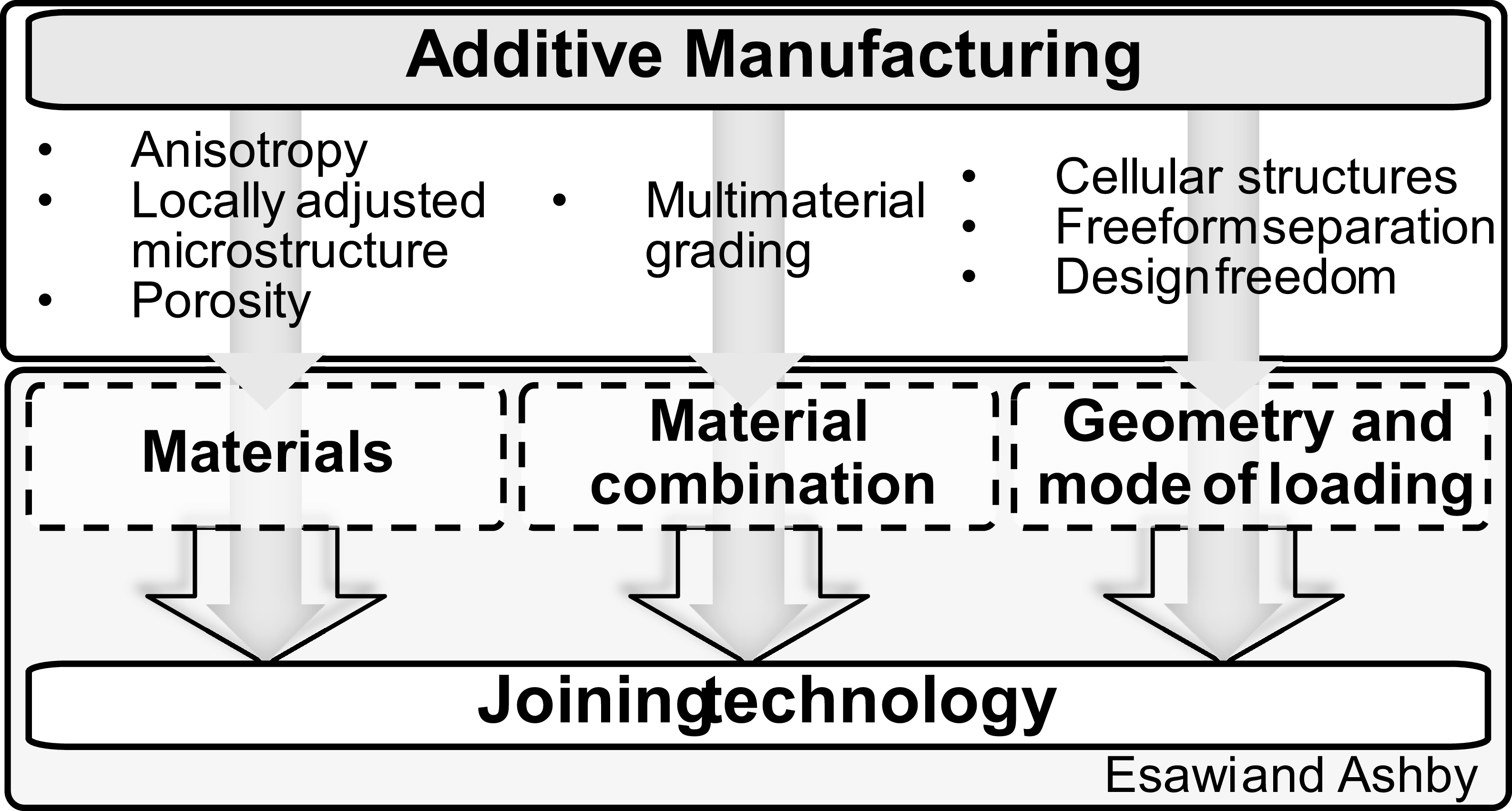
According to Reference Esawi and AshbyEsawi and Ashby (2004), and similarly argued by Reference Das and SwainDas and Swain (2022), JT can be selected based on geometry and mode of loading, material combination and material data. This principle can be applied to AM, as the materials are intrinsically the same as those in CM. However, AM offers new, more complex, or relevant effects compared to CM such as anisotropy which is more relevant due to the layer-wise nature of AM compared to most CM processes of metals (Reference Gibson, Rosen and StuckerGibson et al., 2015).
Figure 3 illustrates the CM-based foundation proposed by Reference Esawi and AshbyEsawi and Ashby (2004), extended to include AM-relevant correlations and criteria. Especially in PBF-LB/M, properties can be adjusted locally, thereby changing material features such as microstructure and porosity. Certain systems enable the manufacturing of multi material components, resulting in tailored properties and material grading. AM allows complex lightweight design due to the enabling nature of the layer-wise manufacturing. For this reason, additional criteria must be considered when selecting JT for AM. (Reference Lachmayer, Ehlers and LippertLachmayer et al., 2024)
AM-specific extension of the JT data model, adapted from Reference Esawi and AshbyEsawi and Ashby (2004)

Reference Esawi and AshbyEsawi and Ashby (2004) identified 53 JT for CM. However, for AM, and especially for specific technologies and materials, JT data is limited. Therefore, the initial proposal of the adapted framework focuses on relevant joints for mechanical industries, such as bolted and rivet joints, welding processes, brazing and adhesion bonding (Reference RothRoth, 1996). Potentials and restrictions of AM were compared qualitatively with these JT to get an understanding of their correlations to further adjust selection and evaluation criteria. These correlations are explained using the example of bolted joints. The addressed potentials and restrictions are design freedom, topology optimization, cellular structures, local property adjustments (microstructure), reduction of joining operations, functional integration, surface quality, anisotropy, property dependency of AM process, accuracy, distortion and mass reduction.
For bolted joints positive influences arise from design freedom and functional integration by enabling the direct manufacturing of complex holes, threads and positioning aids in the form of adapted structures for specific post-processing operations during the AM process (Reference Reichwein, Noack, Ambros, Stork and KirchnerReichwein et al., 2020). Consequently, process operations are simplified. Moreover, locally adjusting material properties along the thread could result in a even load share of the threads, similarly to adapted nut molds (Reference Bender and GerickeBender & Gericke, 2021).
The following paragraph discusses considerations that have a neutral impact. Although, surface quality is worse compared to CM, the preload loss associated with surface roughness and embedding can be partially compensated by retightening the screw after the initial preload loss (Reference Obilanade, Dordlofva and TörlindObilanade et al., 2021; Reference PethPeth, 2022). This weakens the negative influence of surface roughness effects. Assembly loads must be considered for topology optimized parts and especially for delicate cellular structures, as operating and assembly loads may differ in their force effects. This particularly applies to thread-forming screws due to the increased forming forces and moments (Reference Reichwein, Noack, Ambros, Stork and KirchnerReichwein et al., 2020). With respect to accuracy and distortion, a minimal diameter for the hole must be maintained, and depending on the build orientation, truss was observed for holes parallel to the build platform (Reference KranzKranz, 2017). However, both effects can be overcome with subsequent operations, hence resulting in neutral influences.
The following negative influences occur. Research has shown that anisotropy negatively affects the pull-out strength of screws in PBF-LB/M, depending on the hole axis relative to the build direction (Reference Ullah, Akmal, Laakso and NiemiUllah et al., 2020). When combined with cellular structures, adequate wall thickness must be maintained in the screw area. Screws add an extra part to the design, which increases mass and joining difficulty.
This sums up the correlations between PBF-LB/M (AM) and bolted joints. Similar correlations have been performed for the remaining JT. A weighting of these considerations was not performed. Bolted joints, especially with thread-forming screws, benefit from the integration of positioning aids, adapted hole geometry and a reduction of joining operations (Reference Reichwein, Noack, Ambros, Stork and KirchnerReichwein et al., 2020). However, the joint strength was not considered, which limits the applicability of certain JT in metal AM, such as adhesive bonding. The purpose of this comparison was to identify AM-specific criteria that offer synergies and restrictions for JT and to address these within the framework. A strength verification must be performed on the final design after the evaluation process. The reasoning of these correlations forms the basis for their integration into the selection framework. A simplified version of the framework is presented in Figure 4 which is an adjustment of the framework depicted in Figure 1. Figure 4 emphasizes the part features subprocess, one of three subprocesses in the selection process. The other subsequent subprocesses are indicated as black-box models. Each process contains a systematic structure requiring input. Information must be provided or selected using catalogs, such as geometry catalogs. Some AM-specific conditions are introduced through a subprocess, requiring input such as build and surface orientation, as these influence criteria including anisotropy and post-processing. However, inputs related to microstructure changes or surface roughness are required, as these factors are relevant for JT selection in CM and AM and affect JT such as welding due to microstructure alterations (Reference Guzman, Riffel, Evans, Brizes, Avedissian, Farias and RamirezGuzman et al., 2025).
The subsequent evaluation process, indicated in Figure 4, consists of technical and competence evaluation subprocesses. Input for the technical evaluation is provided during the selection process. Within the technical evaluation, the framework assesses build orientation, thermal and electrical conductivity, testability, pre-/post-processing and assembly effort, sealing requirements, dwell time, lightweight potential, cellular structures, and the influence of as-built surfaces on the JT. Design complexity is not treated as a separate criterion in the assessment, as it would introduce redundancy with joint geometry, accessibility of the joint (both part of the selection process), cellular structures, and lightweight design considerations. Criteria such as pre- and post-processing effort of JT are particularly relevant in AM, as functional advantages beyond those achievable in CM can be integrated into the design. An example was discussed earlier in the form of integrated positioning aids for JT processing.
The evaluation processes are based on a combination of qualitative and quantitative data depending on data availability, interpretability, and potential inconsistencies within the underlying data. For pre-and post-processing of JT, data on process duration are derived from manufacturer specifications, literature sources, or approximated for a reference surface based on engineering handbooks and published data. Process operations such as cleaning, degreasing, clamping, milling, thread forming, annealing, sand blasting, coating, and others are covered based on literature such as Reference Růžičková, Sobotová, Beránek, Pelikán and ŠimotaRůžičková et al. (2022). A scoring approach was applied for the JT in 0° and 90° build orientation assuming them as best and worst configuration. Intermediate values were excluded due to inconsistent data. PBF-LB/M and AlSi10Mg were selected as the basis of the database, given their widespread use in metal AM (Reference Gibson, Rosen and StuckerGibson et al., 2015).
The competence evaluation is optional and tailors the solutions to the user’s portfolio and the availability of tools. At the end of the process, JT are presented as a weighted ranking. Excluded JT are listed separately together with their exclusion criteria to provide transparency and inform decision-making.
Simplified selection framework with emphasis on the part features subprocess and an example of a joining-zone geometry

In conclusion, selection criteria and approaches from CM were combined with PBF-LB/M-specific criteria into a selection framework tailored to PBF-LB/M. The framework enables a systematic selection process that accounts for the potentials and restrictions of PBF-LB/M. Based on its CM origin, the framework supports the selection of JT for AM and CM components alike, thereby enabling the application and combination of both technologies.
4. Procedure of the framework and reflection
This section describes the procedure of the selection framework. The framework follows a structured process consisting of requirement definition, weighting selection, technical evaluation, and decision support. The workflow is illustrated using a simplified bicycle frame joining zone rather than a full case study to facilitate the understanding of the framework. The section concludes with a reflection on the potential, limitations and future improvements of the framework.
The overall decision procedure is illustrated in Figure 5. Prior to applying the selection framework, information on requirements, manufacturing process, and component geometry must be specified, while only a preliminary description of the joining zone geometry and loading is required for application in early design phases. In the first step, input parameters such as build orientation, joint geometry, joining zone thickness, joint accessibility, load, materials, disassembly, environmental conditions, coatings, and allowed microstructural changes are defined. The input is provided in standardized formats, including binary, categorical, and numerical entries This input definition ensures reproducibility and prevents scope for interpretation. For example, joint geometry is defined as categorical parameter, the allowance of microstructural change is a binary decision, and joining zone thickness as a numerical parameter influencing feasibility limits. Based on this information, unsuitable JT are excluded. In the example of Figure 5, bolts and screws are eliminated as disassembly is not required. Adhesive bonding is also excluded due to peeling loads caused by combined bending and tensile loading for this joint geometry.
In the second step, the weighting for the technical evaluation is selected. Weighting presets are derived using pairwise comparisons, as certain criteria may be irrelevant depending on the use case. However, the weighting can be adjusted by the user or based on previous evaluations. In this example, thermal and electrical conductivity and dwell time are negligible, whereas lightweight potential is prioritized due to the lightweight design of the bicycle frame, resulting in a higher weighting.
In the third step, the technical evaluation is performed, resulting in the output of a ranking of suitable JT without and with weighting applied. For this exemplary use case and the selected requirements, hard brazing, electron beam welding and friction stir welding are proposed as the most suitable solutions when weighting is applied. However, this ranking depends on user input and does not account for failure behavior, which must be evaluated separately for the detailed geometry.
In the last step, after excluding JT that do not match the user’s competence, suitable JT can be selected. However, the framework does not offer design recommendations for adapting the design to specific JT.
Decision-making process of the JT selection framework for a bicycle frame joint

Figure 5 Long description
The image contains a table and a diagram illustrating the decision-making process for selecting a joint technology for a bicycle frame joint. The table is divided into four main steps: Input & selection process, Weighting, Technical evaluation, and Evaluation process. The table has multiple rows and columns with various criteria and weights assigned to them. The diagram shows a bicycle frame joint with arrows pointing to different parts of the frame, indicating the areas of focus for the decision-making process. The table and diagram together provide a comprehensive overview of the criteria and steps involved in selecting the appropriate joint technology for a bicycle frame.
Based on the previously proposed framework in its conceptual phase, it offers the potential of selecting suitable JT solutions for PBF-LB/M, and with minimal adjustments, for CM. Thus, it not only allows joining of PBF-LB/M components but also combinations of different manufacturing technologies leading toward combined design. The selection process is based on generic geometry information, AM-specific influences, and user needs. However, strength verification is not included within the framework and must be conducted based on the finalized design. In its current form, the underlying database for the framework is tailored towards PBF-LB/M and AlSi10Mg. However, the framework itself is applicable to further materials and manufacturing technologies. More data regarding material and process combinations are required for a broader scope of application. Evaluation criteria must be reassessed for specific materials and processes, as assessments conducted for aluminum, such as process duration, may differ from those of other materials. Furthermore, data about JT in AM is sparse and differs based on machine, process, and material combinations. Hence, an extended database would support the JT selection. Since data and framework are currently limited to PBF-LB/M, a reduced number of JT are implemented. More JT for CM could be integrated to support the development toward combined design. Moreover, the criteria could be adjusted to account for additional AM processes and materials, thereby further expanding the scope of application. In conclusion, the reflection highlights both the potentials and current limitations of the framework, thus providing the foundation for the conclusion and future research directions presented in the next section.
5. Conclusion and next steps
This paper addresses the lack of systematic JT selection in AM. To close this gap, the development of a selection framework was proposed, primarily tailored to the PBF-LB/M process but also applicable to CM and adaptable to further AM processes. For this purpose, established criteria and logic of JT selection and evaluation processes, as well as JT data from CM, were adapted and extended to meet the requirements of PBF-LB/M components made of AlSi10Mg. The selection of AM technology and material was based on their widespread use and the resulting availability of JT data. Consequently, AM-specific factors such as build orientation, local property tailoring, and design freedom are incorporated.
The aim of this study is to develop a selection framework and outline the underlying methodological process with the aim of guiding designers in identifying suitable JT for PBF-LB/M components in early design stages. To achieve this, process and material data, design information of the joining zone, and additional input regarding functional and process requirements are needed. Based on these inputs, unsuitable JT are first excluded before the remaining JT are ranked based on technical and competence evaluation. Building on JT frameworks designed for CM, this approach enables not only the assessment of PBF-LB/M components but also allows hybrid combinations of AM and CM.
Since the framework itself is still under development, limitations remain regarding the number of implemented JT, AM processes, and materials. Moreover, the limited availability of AM-specific JT data constrains the framework. Design complexity, particularly regarding cellular structures and their application in a JT context, can be further detailed as more research becomes available. Future research should focus on integrating additional JT, AM processes, materials, and newly published JT data for AM. Case studies should be conducted to refine framework and its criteria to improve decision-making.
Overall, the proposed framework provides a systematic approach for integrating JT into PBF-LB/M design. Building upon established JT frameworks for CM, it not only facilitates the selection of suitable JT for AM but also contributes to bridging the gap between AM and CM in combined design solutions.
Acknowledgement
This research was funded by the Deutsche Forschungsgesellschaft (DFG – German Research Foundation) under project number 531952402.




 Open access

