

1. Introduction
Drilling into polar ice sheets to retrieve samples of ice cores is crucial in many scientific studies. The information recorded in ice cores can help scientists understand the mechanism of climate change in the past, and assess possible future climate change. The data analyzed from ice cores have also become central to understanding the evolution of the earth's glaciology and the resilience of the life forms exposed to extreme conditions. However, ice core drilling in these regions is a fairly arduous and tedious task. The challenges are posed not only by adverse weather and extremely low surface temperatures, but also the very short field seasons. Therefore, developing powerful fast drilling systems has become an important task for many projects (Clow and Koci, Reference Clow and Koci2002; Goodge and Severinghaus, Reference Goodge and Severinghaus2016; Hu and others, Reference Hu2019).
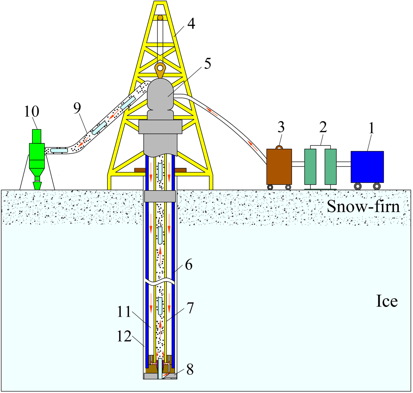
Recently, air drilling with reverse circulation, which has been widely used in normal drilling industries including mineral exploration, geothermal wells, underground water drilling and so on, has been proposed for use in ice core drilling (Wang and others, Reference Wang2017). The main characteristic of this technology is that the air is circulated in a reverse manner as shown in Figure 1. High-pressure air coming from air compressors flows through a dual-channel swivel and the annular space in double-wall drill pipes, and enters into a reverse circulation drill bit. After entraining the ice chips at the bottom of the borehole, the compressed air is directed into the central space of the double-wall drill pipes, and then carried with ice cores and chips up to the surface (Cao and others, Reference Cao, Liu, Chen, Chen and Zhao2018a). The main advantage of this method is that ice cores and ice chips can be continuously returned to the surface as drilling proceeds, and core barrel retrieval is not needed after each run, which saves considerable time. More important, drilling with air reverse circulation effectively addresses the problem of circulation loss in the snow-firn zone since the air does not flow through the annulus between the borehole wall and the drill pipes. The borehole wall is also relatively stable because there is no fluid or chip flow against the walls after the drill bit has passed. Therefore, a casing is not needed in this drilling method, despite it being a must in many cases in snow-firn drilling with air circulation in the past so as to isolate and protect the borehole wall from the air fluid (Bentley and others, Reference Bentley, Bar-Cohen and Zacny2009; Whelsky and Albert, Reference Whelsky and Albert2016).
Schematic diagram of air reverse circulation drilling: (1) air compressor; (2) cooler; (3) dryer; (4) drill tower; (5) swivel with dual wall; (6) outer pipe of drill pipe; (7) inner pipe of drill pipe; (8) drill bit; (9) discharge pipe; (10) cyclone; (11) annulus of the drill pipe; (12) annular space between drill pipe and borehole wall.
Though the air reverse circulation drilling method has been widely used in conventional rock drilling, it is mainly used for full-face drilling (non-core drilling). Only rock cuttings need to be transported to the surface by the air fluid. However, in ice core drilling, not only do the ice chips need to be carried out, but also the ice cores from the borehole bottom need to be conveyed to the surface. Therefore, two points are crucial to determine whether air reverse circulation drilling can succeed with core ice. The first one is whether the large ice cores can be transported to the surface by the air fluid. The second is whether the reverse circulation can be effectively formed with the appearance of ice cores. In the work by Wang and others (Reference Wang2017) and Cao and others (Reference Cao, Liu, Chen, Chen and Zhao2018a), the minimum air volume flow rate and the pressure drop needed to convey ice cores were studied. The results show that the air injection parameters required in ice core drilling are much lower than that of conventional rock drilling if the diameter and the length of the ice core are set as 60 and 250 mm, respectively. Thus, a smaller air compressor is possible to satisfy the requirement of ice core drilling with air reverse circulation. This paper will discuss the reverse circulation effectiveness and the factors influencing this effectiveness in the presence of the ice core.
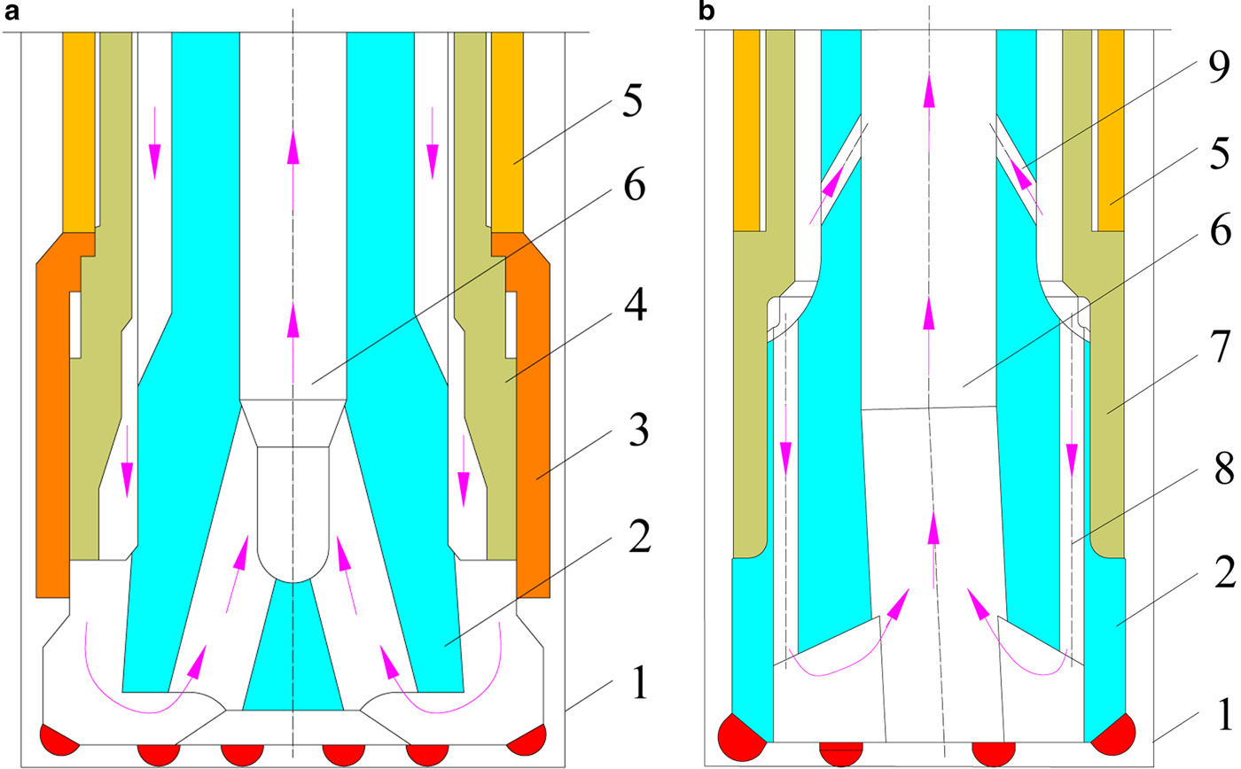
It is known that air reverse circulation is formed by the drill bit during drilling, as the bit is designed to conduct the air and cuttings exhaust in almost their entirety into the central passage of the drill, and prevent their leaking from the annulus between the borehole wall and the drill. Therefore, the drill bit structure is important for forming a strong reverse circulation. In the field of geological drilling, two types of reverse circulation drill bits are widely used. The first type adopts a sealing ring described as a shroud or sleeve to reduce the clearance between the borehole wall and the drill bit, so that a seal or near seal is formed in this annulus to force the air to flow into the central passage of the drill bit as shown in Figure 2a. However, this seal or near seal state is not reliable in broken formations due to an irregular wellbore or wear of the shroud. The sealing ring has to often be adjusted or replaced in the drilling process. The other type of drill bit was developed based on the principle of an air ejector as shown in Figure 2b (Thomas, Reference Thomas2007; Green, Reference Green2008). Several flushing nozzles and inner suction nozzles are designed on the body of the drill bit. When the exhaust air enters the drill bit, some of it exits the flushing nozzles to clean and cool the drill bit. Other air will be ejected from the inner nozzles at high speed to create a low pressure nearby to drag the air and cuttings upward through the central passage of the drill bit. In order to enhance the performance of this type of drill bit, much research has focused on optimizing the structure of both the flushing nozzles and the suction nozzles (Luo and others, Reference Luo2016; He and others, Reference He, Sun, Liang and Luo2018). In some cases, the flushing nozzles were eliminated to improve the effectiveness of the reverse circulation, although the drill bit cutters cannot be cooled effectively since there is no fluid flowing through the borehole bottom (Cao and others, Reference Cao, Chen, Liu, Chen and Wang2017). Despite this type of drill bit being successfully applied in many drilling fields, it cannot be used directly in ice core drilling since it is mainly used for full-face drilling. The existence of the ice core may have a negative effect on the reverse circulation as shown in Figure 3. When the ice core moves near the inner suction nozzles or the ice core is long enough to exceed the distance between the borehole bottom and the suction nozzles, the ice core will disturb the air flow from the inner suction nozzles. The air flow pressure will increase greatly such that some of it may flow downward along the annulus between the ice core and the inner wall of the central passage of the drill bit, which not only weakens the effect of the reverse circulation, but also affects the cleaning up of the ice chips from the borehole bottom.
Air reverse circulation drill bit in rock drilling: (a) drill bit with a shroud; (b) ejector type of drill: (1) borehole wall; (2) drill bit; (3) shroud; (4) drive sub; (5) hammer casing; (6) central passage; (7) connector; (8) flushing nozzles; (9) inner nozzles.
Air reverse circulation in drill bit: (a) without ice core; (b) with ice core: (1) borehole wall; (2) cutter; (3) drill bit; (4) outer tube; (5) inner tube; (6) flushing nozzles; (7) inner nozzles; (8) central passage.

In recent years, the using of a swirling flow is encountered in a wide range of applications in various engineering fields. The basic characteristic of a swirling flow is the combination of axial and tangential velocities, in which the swirl velocity component can be generated by the use of some kinds of swirl generators such as guiding vanes, tangential injection or rotating mechanical devices (Verbeek and others, Reference Verbeek, Bouten, Stoffels, Geurts and Meer2015; Chen and others, Reference Chen, Ho, Abakr and Chan2016). Research has indicated that the swirling flows exhibit stronger shear and centrifugal forces, high rates of entrainment and higher mixing rates. This strong suction effect of the swirling flow is precisely what the reverse circulation drill bit is needed. Our preliminary study also shows that the swirling flow can substantially enhance the reverse circulation effect of the drill bit (Cao and others, Reference Cao, Chen, Liu and Chen2018b). In this paper, an ice drill bit designed with a vane swirler inside was developed, which we call a swirling ice drill bit. An orthogonal design method was adopted to analyze the influence of the swirler structure parameters on the reverse circulation effectiveness of the drill bit, including the helical angle, number of blades and the blade length, etc. Range analysis was used to determine the optimal structural parameters of the swirler. In addition, the influence of ice cores of different lengths on the effectiveness of the reverse circulation was tested. Based on the experimental results, an ice drill bit with the optimum swirler structure was designed and tested.
2. General design of the drill bit
2.1. Working process of the swirling ice drill bit
The basic components of the swirling ice drill bit include the upper and lower parts of the drill bit body, a vane swirler, inner and outer tubes, gasket sealer, cutters mounted to the bottom side and shoes to control the penetration rate, as shown in Figure 4.
Swirling ice core drill bit: (a) working principle of swirling drill bit; (b) 3D models and van swirler: (1) cutters; (2) shoes; (3) lower drill bit body; (4) upper drill bit body; (5) gasket sealer; (6) flushing nozzles; (7) vane swirler; (8) inner tube of drill bit; (9) swirling slot; (10) outer tube of drill bit; (11) outer tube of connector; (12) inner tube of connector; (13) borehole wall; (14) spiral blade.

The inner and outer tubes of the drill bit are connected with the inner and outer tubes of the special connector, respectively, which is attached to the end of the double-wall drill pipes (not shown in the figure). A vane swirler, used to generate spiral flow in the drill bit, is fitted into the central passage of the upper body of the drill bit. Certain spiral blades are designed on the outer surface of the swirler, which can form a spiral slot together with the inner wall of the drill bit inner tube, as illustrated in Figure 4a. Three flushing nozzles are designed inside both the upper and lower parts of the drill bit body. When air from double-wall drill pipe enters the drill bit, some of it is ejected from the swirler at high velocity to generate the swirling flow, which results in the low pressure nearby. Other air exits from the flushing nozzles to sweep ice chips toward the central passage of the drill bit. In the entrainment effect of the swirling flow, the air from the flushing nozzles and the annulus between the borehole wall and the drill tools will be drawn into the central passage of the drill bit to circulate. When the length of the ice core reaches the designed value, the upper part of the ice core will contact the core catchers designed in a wedge shape (not shown in the figure), which are installed on the connector between the drill bit and the double-wall drill pipe. Under the thrust of the core catchers, the ice core breaks and flows upward together with the ice chips.
Considering that the drill bit's cutters do not need to be cooled in ice drilling because of the lower temperature of the borehole, the flushing nozzles maybe not needed when drilling in snow or the firn-ice layer. In this case, all air will be ejected from the swirling slot, so that the suction effect of the swirler is strengthened. This means the effectiveness of the reverse circulation of the drill bit can be greatly improved, which is just what is needed in ice drilling in snow or firn-ice.
It should be noted that, for the swirling ice drill bit, the high-speed air stream ejected from the spiral slot will move upward along the inner wall of the drill bit inner tube, which is obviously different from that of the conventional drill bits discussed above. When the ice core moves near or through the swirler, this air stream will flow upward in the annulus between the ice core and the inner wall of the drill bit inner tube as shown in Figure 4. In this sense, the appearance of the ice core has much less influence on the reverse circulation of the swirling drill bit compared with a normal bit.
2.2. Structure parameters of the swirling drill bit
It is known that an optimally designed drill bit, especially the cutters and shoes, is very important to ice core drilling, because such a bit affects not only the penetration rate, but also the ice core quality (Talalay, Reference Talalay2013). Many types of ice drill bits with different cutters have been successfully designed and tested to improve drilling performance (Gundestrup and others, Reference Gundestrup2002; Johnsen and others, Reference Johnsen2007; Zagorodnov and others, Reference Zagorodnov, Thompson, Ginot and Mikhalenko2005). Therefore, the cutters and shoes for the swirling drill bit can be designed in reference to the above studies, which will not be discussed in this paper. Other structural parameters of the swirling drill bit are shown in Figure 4 and Table 1. In order to recover an ice core with a diameter of 60 mm, the outer and inner diameters of the drill bit body are set at 114 and 68 mm, respectively, which means the clearance between the ice core and the inner wall of the drill bit is ~4 mm. Three flushing nozzles with pressure restoring grooves at the outlet are evenly distributed along the circumference of the drill bit body. These nozzles are located directly above the cutters so as to sweep up the ice chips more easily during drilling. According to our previous study, the height of the swirler should be as small as possible (Cao and others, Reference Cao, Chen, Liu, Chen and Wang2017). Considering the strength and the connection method of the drill bit, the length L 1 is set as 130 mm in this paper.
Basic structure parameters of the swirling drill bit

The swirler is the key part of the swirling drill bit, because the reverse circulation performance of the drill bit is influenced by the entrainment efficiency of the swirler which is closely associated with the tangential and axial velocities of the swirling flow. When the geometric structure of the swirler changes, the characteristics of the swirling flow will change accordingly, which will affect its suction performance. Especially for the swirling drill bit designed with flushing nozzles, due to the varying flow pressure loss, the air mass flow rate flowing through the swirler will change as its geometrical structure changes, which further affects the swirler suction effect. The guide vane swirler is actually a short pipe designed with several spiral blades on its outer surface as shown in Figure 4b. Typical structural parameters of the swirler include the helical angle of the vane blade measured from horizontal α, the number of blades n, the blade length l s and the central angle β.
The total outlet area of the spiral slots A s can be expressed by the following equation:

in which D s1 and D s2 are the outer diameter and the inner diameter of the spiral blades, respectively.
The total outlet area of the flushing nozzles A f can be calculated as

Then the area ratio λ, defined as the ratio of the total outlet area of the spiral slots to that of the flushing nozzles, can be given as

Obviously, determining all these structural parameters of the swirler is important in improving the performance of the swirling ice drill bit as mentioned above.
In order to evaluate the influence of the flushing nozzles on the reverse circulation performance, the swirling drill bit is designed in two forms: with three flushing nozzles (called drill bit I) and without flushing nozzles (called drill bit П).
2.3. Performance evaluation index of the swirling drill bit
One of the most important tasks for the swirling ice drill bit is to form strong reverse circulation when drilling in snow or the firn-ice layer as discussed previously. In analyzing its working principle, the swirling ice drill bit can be perceived to work much like an air ejector. Air ejecting from the swirler works like the primary flow or motive fluid of the ejector, which draws the (secondary) air from the flushing nozzles and the annulus between the borehole wall and the drill bit. Therefore, the performance of the swirling drill bit can be measured by the entrainment ratio η 0, which is defined as the ratio of mass flow rate sucked into the drill bit from the annulus between the borehole wall and the drill bit to that of the supplied air, and it is given as

in which, m 0 and m 1 are the mass flow rate of air supplied from the compressors and the air sucked into the drill bit from the annulus between the drill bit and borehole wall, respectively, kgs−1; η 0 is the entrainment ratio of the drill bit and is dimensionless.
At a given operational condition, the higher the value of the entrainment ratio η 0, the more air is sucked into the drill bit, and then the reverse circulation effect of the drill bit is better.
3. Experiment
3.1. Experimental setup
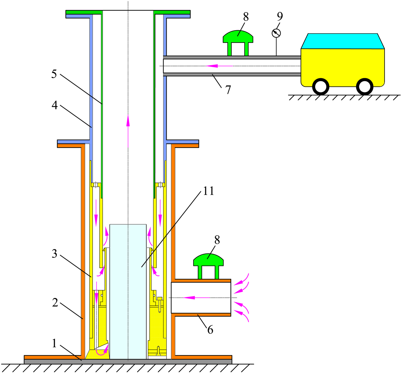
The experimental setup used in the present study is shown in Figure 5. Because the rotation speed needed for ice cutting is low, generally in the range of 50–100 rpm, the influence of the drill bit rotation on the airflow is neglected in the testing for the sake of simplicity. It consists of the base frame, the casing, the swirling drill bit, the outer and inner tubes, the flow rate sensor, the pressure sensor and the air compressor. A 117 mm diameter casing was used as the ice borehole. The clearance between the swirling ice drill bit and the inner wall of the casing was ~1.5 mm, which was equal to the annulus size between the drill bit and the borehole wall in real drilling. The casing was opened to the environment at the outlet of the connector pipe. When the swirling ice drill bit was working, the environmental gas would be sucked into the drill bit through this connector pipe if a reverse circulation was formed. Otherwise, the gas would be blown out into the ambient environment via the pipe. Since in this work only the influence of ice core length on the reverse circulation effectiveness of the drill bit is tested and analyzed, a steel pipe with 60 mm diameter was used instead of an ice core for simplicity. This steel pipe was fixed on the base frame in a threaded manner so that it could be easily changed. The steel pipe length L i was set at 0, 80, 120, 160, 200 and 240 mm, respectively, to investigate its influence on the reverse circulation. A compressor with a volume flow rate capacity of 3 m3min−1 and a pressure of 1 MPa was used to generate the working air fluid.
Experimental apparatus: (1) base frame; (2) casing; (3) swirling ice drill bit; (4) outer tube; (5) inner tube; (6) connector pipe; (7) air inlet pipe; (8) flow rate sensor; (9) pressure sensor; (10) air compressor; (11) steel pipe.
Two vortex shedding flow rate meters of LK-VFF-50 type were employed to measure the volume flow rate of the air from the air compressor and the air sucked into the testing stand from the environment. The range and precision of this type of flow rate were 0.1–100 gs−1 and 1.5%, respectively. One pressure sensor was employed to measure the air pressure from the air compressor. Hot melt adhesive sticks were applied to seal the flushing nozzles when necessary. In order to reduce possible experimental errors, each test was performed three times.
3.2. The orthogonal design
The orthogonal design is a method for a multi-factor experiment, which selects representative points from the full factorial experiment in a way such that the points are distributed uniformly within the test range and thus can represent the overall situation (Roy, Reference Roy1990). By utilizing an orthogonal array, the number of experiments will be greatly reduced. The main purpose of this work was to study the effects of the swirler structure parameters on the reverse circulation performance of the drill bit as mentioned above. Therefore, the helical angle α, number of blades n, blade length l s and area ratio λ adjusted by the central angle β were selected as four factors for the orthogonal design, which were labeled as A, B, C and D, respectively. Each factor has four levels, and the interaction between these factors is not considered in the present study. The entrainment ratio η 0 of the drill bit is chosen as the evaluation index. The factors and their levels are listed in Table 2.
The factors and levels based on orthogonal design

Based on the numbers of factors and levels, an orthogonal experimental design table of L 16(45) was adopted to arrange the test (Roy, Reference Roy2001). Here, the notation L indicates the name of the orthogonal table. The number 16 denotes the main body of the table with 16 rows. Thus, 16 group experiments are needed in total to carry out and complete the optimization process in the study. The number 4 denotes that each factor has four levels. The number 5 indicates that the table has five columns, which means a maximum of five factors can be considered in the design table. Therefore, the four factors of this study can be filled in any four columns arbitrarily, and another column can be kept as the null column (Cavazzuti, Reference Cavazzuti2013). This blank column can be used as an error factor to estimate test errors. In addition, the test order is random to avoid subjective bias. The layout of the experiment is listed in Table 3.
Experiment results of swirling ice drill bit

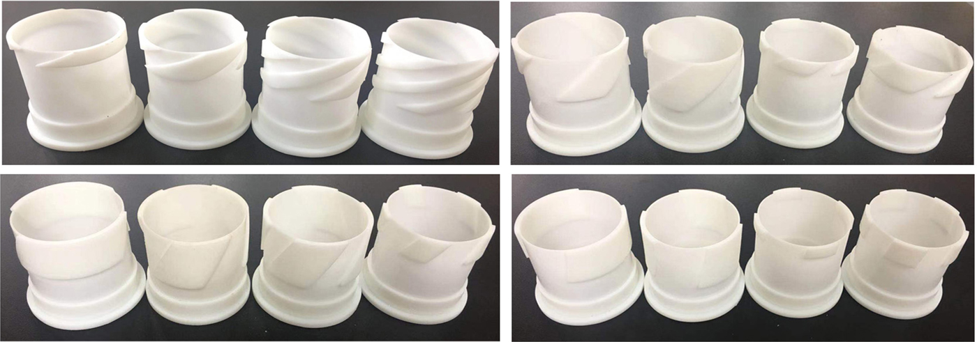
Given the structure and quantity of the swirlers, they were produced by high-resolution laser SLA 3D print technology with a photosensitive resin material as presented in Figure 6. The print precision is ~0.1 mm. Other parts of the drill bit were produced with standard steel.
Swirlers produced by 3D print technology.
3.3. Range analysis method
Range analysis is the statistical treatment most commonly applied to the results of the orthogonal experiment to measure the sensitivity of the factors to the evaluation indices and to determine the optimal level of different factors (Roy, Reference Roy2001). In this method, range value R is introduced to reflect the extent of the factors influencing the evaluation indices, which can be calculated as (Xi and others, Reference Xi, Zhang, He and Huang2019)


where i is the factor notation from A to E, and j stands for the level of the factors, from 1 to 4 in this study. R i is the range value of factor i. y j, n and k i, j present the experimental value and its mean value of the index for factor i at level j. N means the total number of levels, equal to 4 in this study.
According to Eqn (5), the larger the value of R, the more significant the factor. In addition, a maximum value of k i, j is the optimal combination of the factors.
4. Results and discussion
4.1. Results analysis of the swirling drill bit I
4.1.1. The entrainment ratio
The experiment results for drill bit I are listed in Table 3. It can be seen that the swirler structure has a strong influence on the reverse circulation performance of drill bit I. Under the same conditions, the reverse circulation cannot be formed at all even without an ice core for some swirlers, such as in testing groups 2, 3, 4 and 8 as indicated in Table 3. The reason may be that under these cases, the air flow resistance of the swirler is high enough such that most of the air is ejected from the flushing nozzles rather than the swirler, so its suction effect is seriously weakened or even disappears. In addition, the existence of the ice core in fact greatly affects the reverse circulation effectiveness of drill bit I. For example, for testing groups 1 and 10, the drill bits have weakened suction effects when they are working without ice cores, with the η 0 value of 8.91 and 6.85%, respectively. Yet, this suction effect disappears when the ice core appears. For other groups, the value of η 0 is reduced when the ice core appears, and it will be gradually recovered when the ice core length is longer than 200 mm as illustrated in Table 3. This is because the ice core occupied most of the space of the central passage of the drill bit, so the air flow pressure in the annulus between the ice core and the inner wall of the drill bit increases, which results in the reduction of the air sucked into the drill bit from the environment. Yet, when the ice core is long enough that its position exceeds the outlet of the swirler, an annular space is formed between the ice core surface and the inner tube of the drill bit, so the air after ejection from the swirler will continue to flow upward at high speed in this annulus. Hence, the suction effect of the swirler is strengthened, and more air is dragged into the drill bit. In sum, deterioration of the reverse circulation performance of the drill bit mainly occurred when the length of the ice core was <160 mm, which should be a main consideration in the design of the drill bit.
It should be further noted that the value η 0 of testing group 14 is the largest for most cases as listed in Table 3. Even when the ice core lengths were ~120 and 160 mm, its η 0 values were only slightly smaller than that of testing group 12. Therefore, as regards the swirler structure of the testing groups, group 14 was the best compared to the other groups in terms of entrainment ratio for drill bit I, and its combination was A 4B 3C 1D 4. Nevertheless, according to the orthogonal theory, further analysis is required to confirm the optimal structure parameters.
4.1.2. Results of the range analysis
Based on Eqns (5) and (6), the range analysis results for the entrainment ratio of swirling drill bit I are demonstrated in Table 4. It can be seen that the factor effect as represented by R i on the entrainment ratio of the drill bit is slightly different depending on the length of the ice core. Among the four factors, the range values of factors A and B are the largest and the smallest in all cases, respectively. The range values of factor C are greater than that of factor D when the ice core length is lower than 160 mm, while this order is reversed if the ice core length increases. Taken all together, the four factors of sensitivity for the entrainment ratio of the drill bit are arranged in an A > D > C > B sequence. This is to say, the helical angle of the swirler blade can be considered to be the most influential factor in terms of the reverse circulation performance of the drill bit whereas the number of blades is the least influential.
Range analysis of entrainment ratio η 0 (%)

In order to investigate the influence of each factor on the reverse circulation performance of drill bit I, the relationship between the mean value η 0 (k i, j) of each factor and the factor levels are given in Figure 7. As can be seen from Figure 7 (a) for factor A, the value of the mean η 0 increases rapidly when the level changes from 1 to 4, and the maximum value is obtained at level 4 for all cases. This may be because under the same conditions, the larger the helical angle, the lower the flow resistance of the swirler, and the stronger the suction effect of the drill bit.
Relationship between mean values of entrainment ratio and factor levels for the drill bit I: (a) Factor A (helical angle); (b) Factor B (number of blades); (c) Factor C (blade length); (d) Factor D (area ratio).
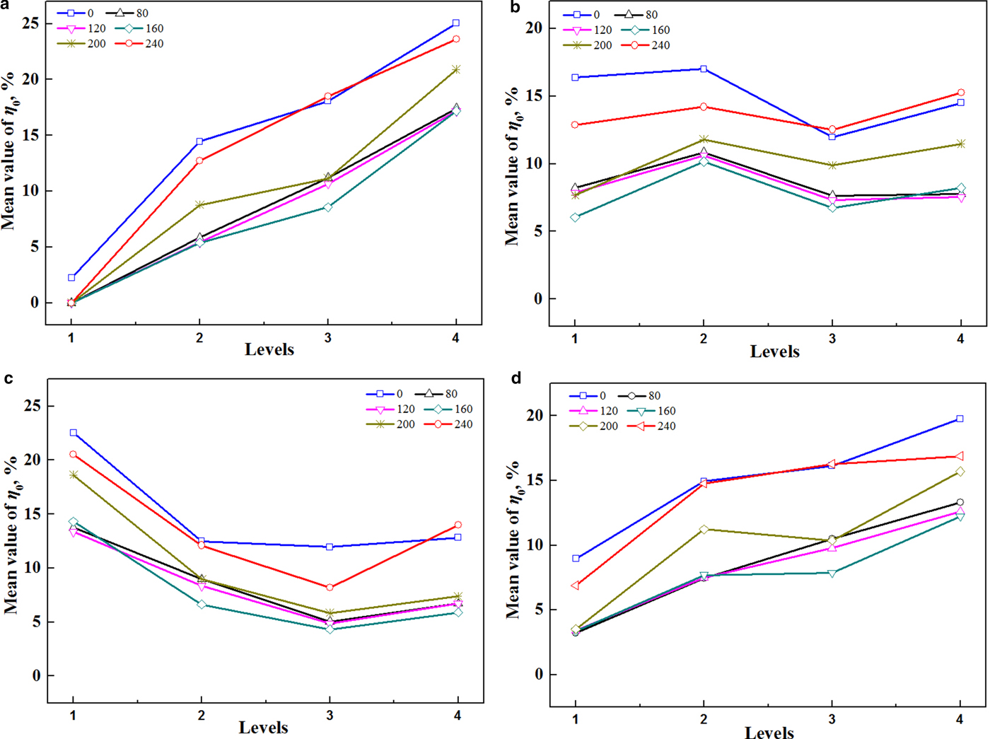
The influences of factor B are not clear enough as shown in Figure 7b. When the level changes from 1 to 3, the value of the mean η 0 first increases then decreases, while it is raised again at level 4. The highest value occurs at level 2 for most cases aside from the ice core length of 240 mm. Thus, level 2 can be chosen as the optimal level for factor B.
Figure 7c demonstrates the influence of factor C on the entrainment ratio of the drill bit. It can be seen that the increase in the blade length causes an overall decrease of the mean η 0 value until the level reaches 3 followed by an increase when the level changes into 4. The maximum value is obtained at level 1. The reason is that the shorter the blade length, the lower the pressure resistance of the swirler, which is beneficial in improving its suction effect.
From Figure 7d it can be seen that for factor D, the mean value of the entrainment ratio increases when the level changes from 1 to 4 aside from the case of the ice core length of 200 mm. The highest value is obtained at level 4 for all cases.
Based on the results shown in Table 4 and Figure 7, the optimal level composition of factors for the drilling bit I can be speculated to be A 4B 2C 1D 4.
4.1.3. The entrainment ratio of the optimal drill bit I
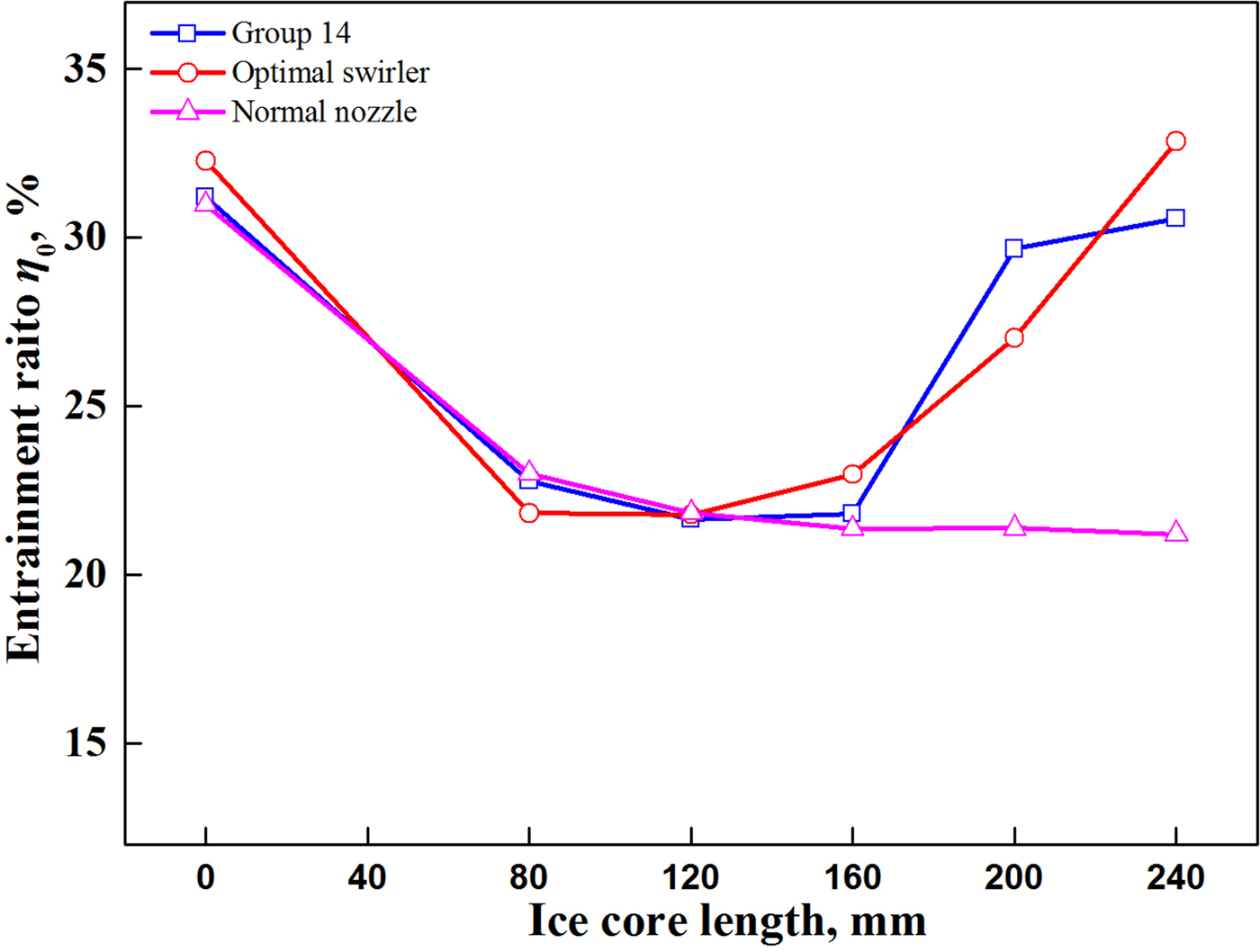
The results in Table 3 indicate that the entrainment ratio of testing group 14 is the best and its combination is A 4B 3C 1D 4, while the optimized levels in the range analysis results are A 4B 2C 1D 4. Thus, another experiment is needed to carry out to test the real performance of drill bit I with the optimal swirler structure. In addition, it should be noted that the suction effect of the drill bit increases with an increase in the helical angle based on the results of Table 4 and Figure 7. It is necessary to verify whether the spiral blade can help to improve the suction effect of the drill bit. Thus, another swirler was designed with the helical angle 90°, and other parameters are the same as the optimal one. In this case, the swirler becomes a conventional inner nozzle with three small outlets (referred to as Normal nozzle). The results are presented in Figure 8. It can be found that the η 0 values of the optimal swirler are not too different from the results of group 14. When the ice core lengths are 80 and 200 mm, respectively, the η 0 value of group 14 is slightly larger than that of the optimal swirler, while it is the opposite for other cases. The main reason is that the difference between these two combinations is only the level of factor B, while it is the least sensitive of the influential factors. Moreover, for drill bit I, the η 0 values of the swirler are greatly higher than that of the normal nozzle when the ice core length exceeds 160 mm. Therefore, the design of the swirler indeed can enhance the reverse circulation performance of the drill bit.
Comparison between testing group 14 and the optimal group for drill bit I: (a) Factor A (helical angles); (b) Factor B (number of blades); (c) Factor C (blade length); (d) Factor D (area ratio).
4.2. Results analysis of the swirling drill bit П
4.2.1. The entrainment ratio
If the swirling ice drill bit is designed without flushing nozzles, all supplied air will be ejected from the swirler. The air velocity flow from the spiral slot will be improved compared to conditions with the flushing nozzles. Then the suction effect of the drill bit will be strengthened and more air will be sucked into the drill bits.
The entrainment ratios of drill bit П are given in Table 5. It can be seen that a strong reverse circulation is formed no matter how long the ice core is. In addition, just like that for drill bit I, both the swirler structure and the ice core length have a certain effect on the reverse circulation. For some swirlers, the appearance of the ice core can greatly reduce the value of η 0, such as for testing groups 3, 8 and 11. While for the testing groups 9, 13 and 16, the values of η 0 are only slightly reduced due to the presence of the ice core. Yet, for testing group 15, the existence of the ice core makes the values of η 0 even increase. Moreover, testing group 15 is also the best group when the ice core is present. Its combination is A 4B 2C 4D 3.
Experiment results of swirling ice drill bit П

4.2.2. Results of the range analysis
The range analysis results for the swirling drill bit П are shown in Table 6. It can be seen that the effect of the factors on the entrainment ratio of the drill bit is changed with the varying length of the ice core. Considering the cases with short ice core, four factors sensitive to the entrainment ratio of the drill bit are arranged in an order such that A > B > C > D. Comprehensively, the helical angel is the most significant of factors, while the area of the swirling slot has a minimum impact, relatively speaking.
Range analysis of entrainment ratio η 0 (%)

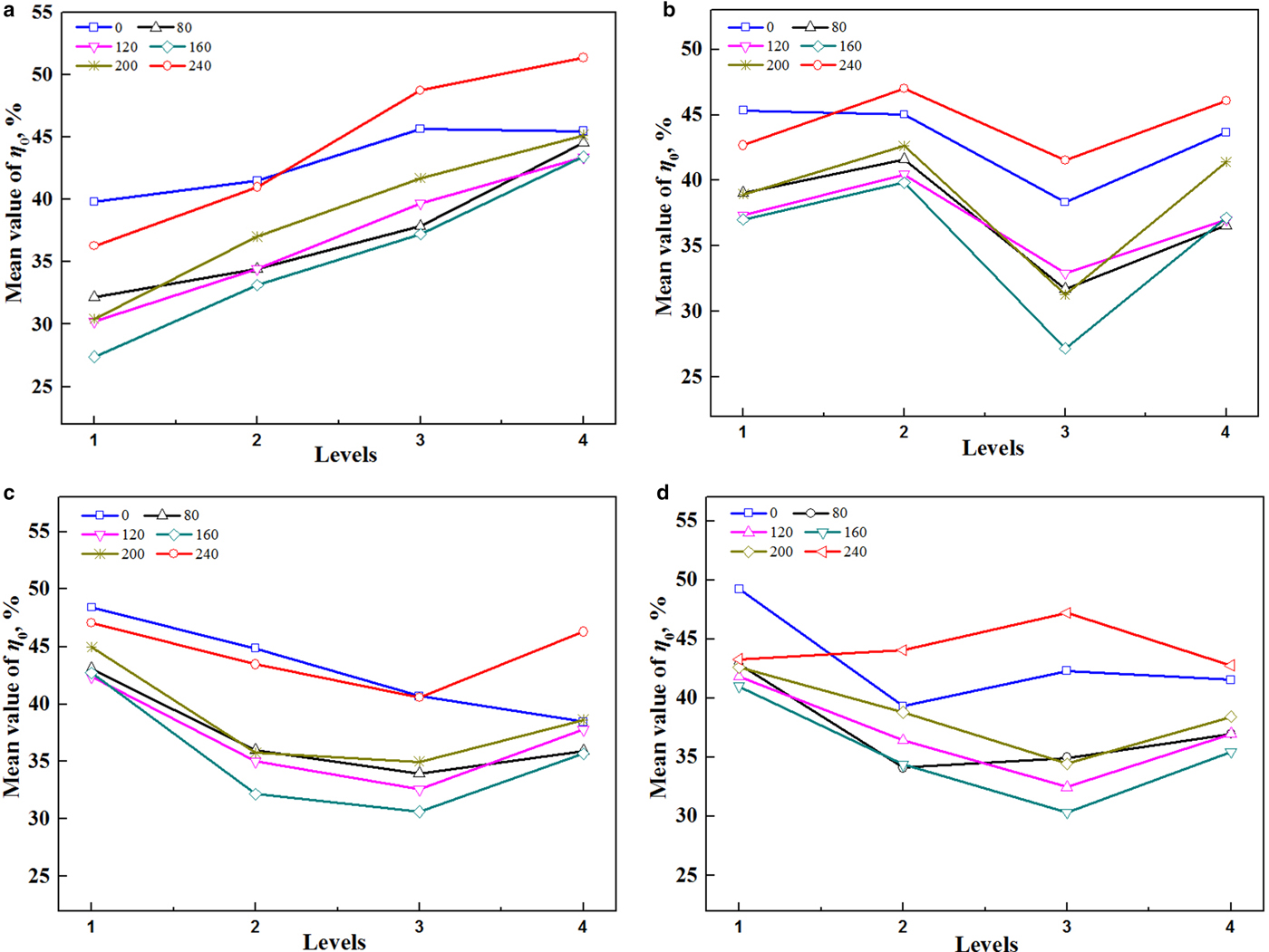
The relationships between the mean value η 0 (k i, j) of each factor and the factor levels for drill bit П are given in Figure 9. For factor A, the value of the mean η 0 increases quickly when the level changes from 1 to 4 aside from the case without ice cores, and the highest value occurs at level 4. Hence, under the conditions where the ice core exists, the larger the helical angle, the better the reverse circulation effectiveness of drill bit П. The influence of factor B is still not clear enough as illustrated in Figure 9b. The maximum value of the mean η 0 is obtained at level 1 for the case without ice cores, while it occurs at level 2 for all other cases. For factor C, the optimal level also occurs at level 1 for all cases aside from the condition of 240 mm ice core length, which means the shorter the blade length, the better the suction effect of the drill bit. From Figure 9d it can be seen that for factor D, the highest of the mean η 0 values is obtained at level 1 for all cases aside from the case of 240 mm ice core length. Thus, the outlet area of the swirling slot should be as small as possible if the flushing nozzles of the drill bit are not in the design. Based on the results from Figure 9, the optimal options for the combination of four factors can be deduced to be A 4B 2C 1D 1 for drill bit П.
Relationship between mean values of entrainment ratio and factor levels for the drill bit П.
Comparing the best combinations of drill bit I and drill bit П, which are A 4B 2C 1D 4 and A 4B 2C 1D 1, respectively, it can be seen that the only difference between them is the change in the level of factor D. Since factor D is the least important factor for drill bit П, the combination A 4B 2C 1D 4 can be used as its optimal combination for convenience. That is to say, the optimal combination is the same for both drill bits.
4.2.3. The entrainment ratio of the optimal drill bit П
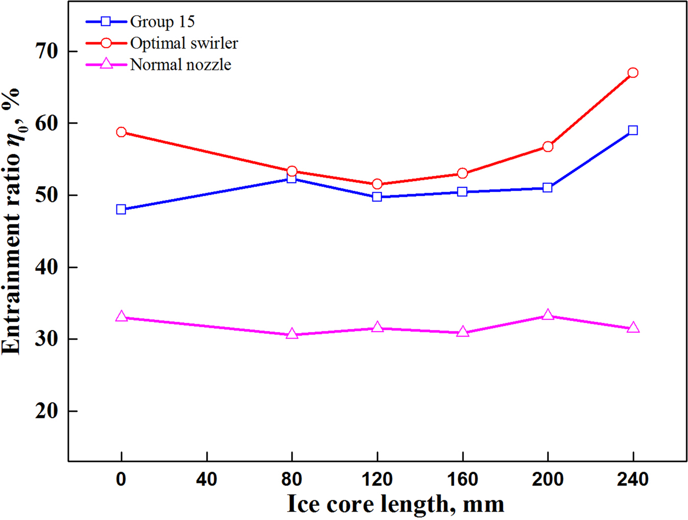
The real performance of drill bit П with the optimal swirler structure is shown in Figure 10. It can be found that the η 0 values of the optimal swirler are larger than that of group 15 in any testing conditions. The minimum entrainment ratio of its drill bit is >50%, which shows a strong capability to form reverse circulation. It is worth noting that compared with the normal nozzle, the swirler can greatly enhance the suction effect of the drill bit П regardless the length of the ice core.
Comparison between testing group 15 and the optimal group for drill bit П.
However, it should be pointed out that the ice chips generated at the borehole bottom can only move upwards by the suction of the drill bit if the flushing nozzles are not part of the design. When the penetration rate of the drilling is fast so that a large amount of ice chips is generated, this suction effect may not be enough to ensure that all ice chips are carried out of the bottom in a timely fashion. This needs to be studied further and discussed in the future.
5. Conclusions
(1) A new type of reverse circulation drill bit, characterized by its vane swirler design inside, was developed to recover the core in ice drilling. From the view of reverse circulation formation, this type of drill bit works much like an ejector. When the compressed air is ejected from the swirler, the pressure nearby decreases so that ice chips and the air from the annulus between the borehole wall and the drill are sucked into the drill bit, and then move upward to the surface together with the ice cores through the central passage of the drill tools.
(2) An orthogonal method was employed to investigate the influence of the swirler structure parameters on the reverse circulation performance of the drill bit. The helical angle, number of blades, blade length and area ratio are the four parameters affecting the suction effect of the drill bit. For drill bit I, the effect of the helical angle was most obvious, the effect of the blade length followed, and the number of blades has a minimal effect. However, for drill bit П, the helical angle and the outlet area of the swirling slot are the dominant and the least important factors.
(3) The appearance of the ice core has a certain influence on the entrainment ratio for both drill bits. In general, when the ice core length is shorter than 160 mm, the entrainment ratio of the drill bit is smaller, while it is quickly improved if the ice core length becomes longer than 160 mm.
(4) The range analysis shows that the best combination of swirler structure parameters for both drill bits is a helical angle of 80°, blade length of 10 mm, area ratio of 6 and number of blades at 2. In this case, the minimum entrainment ratio of drill bit I is ~21.77%, while it can reach 51.51% for drill bit П.
(5) Subsequent work will involve the production of double-wall drill pipes and accessory equipment. Then the reverse circulation performance of this swirling ice drill bit will be tested in real ice drilling.
Supplementary material
The supplementary material for this article can be found at https://doi.org/10.1017/jog.2019.76
Acknowledgement
The authors thank the anonymous reviewers and the editor for their useful remarks and comments. This paper was supported by the National Natural Science Foundation of China (project No. 41976213).
Conflict of interest
The authors declare that there is no conflict of interest.


 Open access