


1. INTRODUCTION
Various attempts at making holes in ice for sampling or for access to the bed have taken place since the late 19th century (Talalay, Reference Talalay2016), however ice drilling began in earnest in the 1950s. A good summary of the drilling technology is presented by Bentley and others (Reference Bentley, Bar-Chohen and Zacny2009) or Talalay (Reference Talalay2016). Since then ice drilling has generally converged with the majority of polar ice drills falling into two categories, ice core drills used when collecting ice samples and hot water drills for access to lake or ocean cavities below the ice, or to sub-glacial sediment, although there are some notable exceptions. Ice core drills tend to be wireline drills which are lightweight but relatively slow, as retrieving each length of ice core involves the drill sonde traversing the complete depth drilled twice before drilling the next ice core. Hot water drills drill very fast, however the weight of the equipment and fuel and the destruction of the ice as well as the short access time has limited its use. More recently, there have been developments using coiled tubing to produce faster mechanical drilling techniques (Clow and Koci, Reference Clow and Koci2002).
In 2004 as part of the International Partnerships in Ice Core Sciences (IPICS) the leading deep ice core drillers from around the world met in Zugspitze in Germany and produced a white paper on Ice Core Drilling Technical Challenges (Whilhelms and others, Reference Whilhelms2004). In the paper the ‘development of a rapid access technology, and better utilization of the borehole once coring operations are completed (e.g. various logging methods or the emplacement of instrumentation in the hole)’ was stated as a future requirement. These drill technology requirements also address the ‘oldest ice’ challenge initiated by a second IPICS white paper (Wolff and others, Reference Wolff2006). As a result four rapid drilling approaches have been recently developed (Witze, Reference Witze2015), these are the US RAID, SUBGLACIOR, RADIX and the British Antarctic Survey (BAS) Rapid Access Isotope Drill (RAID) described in this paper. The US RAID, uses a modified off-the-shelf rock drilling rig and industry standard drill pipe and should be able to drill through 3 km of ice in 200 hours. The drill allows ice and rock samples to be collected by deploying wireline drill through the centre of the pipe drill. As the system weight, without fluid, is over 100 tonnes, a tractor traverse is required to relocate it (Goodge and Severinghaus, Reference Goodge and Severinghaus2016). SUBGLACIOR is an electromechanical drill that combines a laser spectrometer capable of measuring methane and deuterium isotope ratio on-board. The ice is turned into chippings by an auger type drill and these chippings are transported back to the surface by circulating drilling fluid. The ice for measurement is sampled by a heated probe at the front of the auger drill. The drilling speed should allow 3 km of ice to be drilled through in <90 days. The system fits into eight containers, four of which contain the drilling fluid (Alemany and others, Reference Alemany2014). The weight of the system is ≈20 tonnes, without fluid (personal correspondence from O. Alemany, 2017). The RADIX is a small diameter (20 mm) coiled tubing drill. This uses a fluid, in this case a silicone oil, to drive a downhole hydraulic motor. The motor spins cutters to produce chippings which return to the surface with the fluid. By producing such a small hole, less material is removed and the power requirements are smaller. If a penetration rate of 10 mm s−1 can be achieved then 3 km can be drilled in ≈4 days. Small diameter loggers may then be deployed into the borehole. With a 20 mm outer diameter this depth of borehole will still require over 1000 kg of drilling fluid (Schwander and others, Reference Schwander, Marending, Stocker and Fischer2014). All three approaches achieve their rapid drilling speeds by drilling through the ice sheet in one pass rather than tripping like a wireline drill.
The BAS RAID takes a different approach to address the ‘oldest ice’ challenge by measuring the geothermal heat flux as well as on obtaining ice samples for stable water isotope analysis, for climate records and for cosmogenic isotope analysis, for dating. Rather than drill through the ice sheet in one pass, the concept of the BAS RAID system is to markedly increase the speed of the conventional tripping of a wireline drill. The aim of the drill was to drill a borehole rapidly to a depth of 600 m while allowing the collection of isotope samples in chronological order for analysis. The drill was also designed to be lightweight and easily erected and operated by two people. The borehole would then be available for deployment of temperature measurement systems, in order to obtain a temperature profile of the top 600 m of the ice sheet. Hindmarsh and Ritz (Reference Hindmarsh and Ritz2012) showed that a temperature record through only part of the ice-sheet depth might be sufficient to determine basal temperature and geothermal heat flux providing the temperature measurements are precise enough. The method can be further enhanced by removing uncertainties. The age-depth profile, obtained from the isotope samples and vertical strain rates produced using phase-sensitive radar (Nicholls and others, Reference Nicholls2015), can be used to do this. The target depth of 600 m was chosen as this depth could be sufficient in the Dome C area where ice-sheet thickness is ≈3 km.
The rest of this paper describes the drill system in detail. The two seasons where it has been tested and the two seasons where it was deployed close to Dome C are described and future ideas are discussed.
2. DRILL SYSTEM DESCRIPTION
This section describes the current drill system. However, this will continue to be modified and optimised as more is learned after every test and scientific drilling season.
The drill is an electromechanical wireline drill and as such is very similar to a conventional ice core drill. However, rather than collecting a core, auger style cutters are used to remove all the ice as chippings. Wireline drilling is extremely lightweight, especially when drilling dry, when compared with oil pipe drilling as adding extra depth is achieved by adding cable. However, it becomes increasingly slow as you drill deeper as it becomes dominated by trip times, up and down and by time on the surface emptying the drill. The BAS RAID was designed to address both of these issues while retaining the lightweight nature of the wireline drill.
For a wireline drill, if we neglect acceleration, the total time to drill to a depth is shown below in Eqn (1) (adapted from Suzuki and Shiraishi (Reference Suzuki and Shiraishi1982)). Where t is the total time, δ is the depth, l is the length of each drop, V is the winch speed, v is the drilling speed or rate of penetration and s is the surface time. The surface time is the fixed time required to empty and clean the drill. n = δ/l and is the number of drops required to reach a certain depth.
 $$t = \displaystyle{{n^2l} \over V} + n\left( {\displaystyle{l \over v} + s} \right) = \displaystyle{{\delta ^2} \over {lV}} + \displaystyle{\delta \over v} + \displaystyle{{\delta s} \over l}$$
As mentioned before, times become dominated by trip times the deeper the drill goes as is shown by the δ2 term in the equation. Usually it is not possible to change the δ term as this is determined by the science need. From Eqn (1), however, it can be seen that to reach a certain depth as fast as possible we have to increase the winch speed V, the rate of penetration v or how deep we can drill each drop l. We can also shorten s, the time on the surface. The design of the BAS RAID strives to do this.
With the BAS RAID there is no core to break so we do not need to build in sufficient peak winch torque for core breaking, and instead the winch can be optimised for speed while remaining lightweight. Another unusual feature of the design is that the outer barrel is attached to the cutter head and rotates whereas in a conventional ice core drill an inner barrel rotates and the outer barrel is stationary. The chippings are collected internally by a stationary spiral within the drill sonde. The chippings remain roughly in the same order as they were drilled. When the drill sonde is full, it is returned to the surface where it is emptied. This emptying is simply achieved by switching the drill motor to run backwards and the chippings are expelled, once again roughly in the same order that they were drilled. The drill sonde remains in the upright position and is only ever lowered to the ground during the set-up, changing barrels and once drilling is complete. Time on the surface is minimised in this way.
Throughout the design and development there has been a drive to ensure that the system remains lightweight and can be operated with as few personnel and as little operator intervention as possible. To this end automated winch control modes, automatic logging and methods to raise the 9.9 m mast were developed.
2.1 The drill sonde
As mentioned above, in order to create a borehole as fast as possible we need to penetrate the ice as quickly as possible. In order to winch as fast as possible the drill sonde should be as light as possible and therefore as small as possible. Simple machining equations (Machinability Data Center, 1987) show that the power required to create a hole scales with material removed and hence the square of the diameter of the hole. A smaller hole will allow a smaller motor to be used and hence a lighter drill sonde to be realised. However the packaging of the internal components in the drill becomes more difficult if the drill diameter is reduced too much. Many ice core drills produce a ≈100 mm ice core with a borehole of ≈130 mm being produced. A compromise diameter for the long outer barrel of 76.3 mm (3 inches) was chosen to allow an off-the-shelf stainless steel tube (10 AWG ≈1.5 mm wall thickness) to be used for its construction.
It is also true that less cutting power is required to cut an annulus in the ice in conventional ice coring and more is required for full diameter drilling and this is a disadvantage of the BAS RAID. As the power requirement is higher for full diameter drilling the anti-torque requirement will also be higher and the fact that chippings are less dense than ice and so take up more room in the barrel are also disadvantages. We have found that the disadvantages of higher cutting power, higher anti-torque requirement and low chipping density for the full diameter drilling are outweighed by the advantages of only producing chippings.
Once the diameter of the drill had been chosen, a suitable motor was sought to fit into this package. Tests carried out on ice in the cold facilities at BAS showed that a 250 W, 45 mm diameter motor might be suitable. This was upgraded to a 400 W, 60 mm diameter motor after the first field season at Little Dome C, where we found that the torque generated was not quite sufficient. Both of these motors are extremely compact, are rated to 48 V and are brushless. Brushless motors tend to be more powerful for a given size as the windings are on the stator, on the outside of the motor, allowing heat to escape more easily. Brushed motor control is simpler but the windings are on the rotor, hence heat is more difficult to remove and the motors tend to be less powerful. In our case the depth of the desired borehole (600 m) leads to a certain length of cable (650 m), and in order to remain lightweight we use the smallest diameter cable available. However with this low voltage and high current the losses in a thin cable would become too high. The solution is to transmit the power at a high voltage and convert to 48 V in the drill sonde. Both the cable length and the power conversion require that the motor controller be housed in the drill sonde.
In summary the key parameters here that were initially decided, were the drill diameter and the desired depth. These constraints led to the choice of a brushless motor. Once these choices have been made much of the rest of the design follows. A drawing of the complete drill sonde is shown in Fig. 1 where the four sections are shown. It should be noted that Fig. 1 shows the drill sonde with the short barrel attached with the overall length of the sonde being 3.47 m. With the long barrel attached the overall length of the drill sonde is 6.35 m. The complete drill system including winch system, generators, spares (including two drill sondes and drill controllers), set up equipment and tools weighs a total of 725 kg. A photo of the drill system with the long barrel is shown in supplementary file S1. The details of each section are described below.
Drill Sonde, showing the four main sections of the drill (with the short barrel attached).

2.1.1. Anti-torque section
The anti-torque section is a reduced-diameter version of the BAS intermediate drill anti-torque section (Mulvaney and others, Reference Mulvaney, Bremner, Tait and Audley2002). Anti-torque in this design is provided by pushing three radial skates out against the sides of the borehole. The skates are pushed out at the top by a spring, the strength of which is chosen to retract just as the cable lifts the empty sonde. The lower part of the skates is pushed out by a cam that is actuated by the rotation of the motor section so that the more the motor section tries to twist relative to the anti-torque section the more radial force is provided by the cam. The skates each hold two hardened blades which can be swapped depending on the depth and ice conditions. This anti-torque design has been extremely reliable, and we have no need for a slip ring on the cable. An outline of the design is shown in Fig. 2.
Anti-Torque section.

A fork termination on the winch cable is attached to the top lifting eye on the anti-torque section and the electrical connections are made with a 12 pin bayonet type connector on top of the anti-torque section but offset from the central axis.
Electrical connection from the top connector is ‘straight-through’ (where the pin number is identical for each conductor i.e. pin 1 connects to pin 1) to a similar, but opposite gender, 12 pin bayonet connector. This arrangement allows the anti-torque section to be removed from the drill sonde for independent testing of the motor section with the same test cable or the winch. The multi-conductor cable for the electrical connection runs down the side of the section between two sets of skates and then passes through the centre of the cam shaft that is also the mechanical connection to the motor section below. The end cap of the motor section is usually attached to the anti-torque section for transportation and joining the sections is carried out at this point.
2.1.2. Motor section
The right choice of the drill motor should provide enough power for cutting of the ice, rotating of the core barrel and transporting of the ice cuttings with the highest efficiency and the lowest power loss. Having chosen our borehole diameter and the length of the chipping barrel (see Barrel Sections below), the motor power requirements can be estimated. For these calculations our starting point was estimated a rate of penetration (ROP) of 0.25 m min−1 (required to drill at a reasonable rate) and cutter speed of 110 rpm. This rotational speed is based on 85 rpm regularly used with BAS 4 inch ice core drill (rotational speed is proportional to the inverse of the diameter (Machinability Data Center, 1987)).
Adapting the equations described by Talalay (Reference Talalay2003) the required output power of the motor for an electromechanical auger drill can be described by:
 $$ N_{\rm s}=k(N_{\rm c}+N_{\rm r}+N_{\rm t})$$
Where k is the safety factor in case of sludging, sticking, etc…(we use k=1.2); N c is the power required for cutting the ice. N r is the power required in rotating the outer barrel or inner barrel and is a combination of friction and eccentricity. N t is the power required to transport the cuttings up the auger spiral.
Using Eqn (2) and variables specified in Table A3, the required output power of the motor for the BAS RAID was calculated for various speed and ROP, in order to choose a suitable motor. Table 1 shows these results.
Motor power requirements

It can be seen from Table 1 that a 250 W motor is only just adequate for our drill in this operation region however initial cold room tests suggested that the cutting power N c requirement would be lower and for the first three seasons a 250 W motor was used (see supplementary file S1 for details). In the final season this was upgraded to a 400 W. It is clear from Table 1 that this is adequate and measurements show that for our drill we rarely reach this power or torque demand. The motor is an EC60 motor produced by Maxon Motor with a nominal speed and torque of 4960 rpm and 768 mNm, respectively. We use a 15:1 reduction gearbox to achieve the correct cutter speed (note that there is another epicyclic module that further reduces the rotation speed which is described later in this section). As mentioned earlier, once a low voltage brushless DC motor was chosen this necessitated a motor controller and power converters to be located close to the motor so that a lightweight cable could be used.
We use a nominal 375 VDC supply voltage to provide power down the cable and convert to the nominal 48 V required for the motor. A DC to DC converter capable of converting 600 W with a 98% efficiency has been found to work well. A custom PCB to interface the DC to DC converter with the external passive electronic components was designed. A custom heatsink that removes heat efficiently to the motor section housing was also designed.
We use a motor controller which is well matched to our 400 W motor, having a nominal maximum voltage of 50 V and continuous current of 15 A. The controller communicates with the drill controller on the surface using CAN Bus. The motor incorporates a thermistor into the winding which permits the temperature of this to be monitored. Having this thermistor allows the motor to be overdriven and operated at a higher current at low temperatures until a threshold temperature is reached, after which the motor is operated at the maximum continuous current. The motor controller incorporates two analogue inputs, one of which is used to monitor the thermistor resistance and the other is used to measure the motor controller PCB temperature. Once again a custom PCB was designed to interface the motor controller with the motor and other required external components. Details of the main electronic components are included in the Appendix in Table A2.
A final complication to our design is that we rotate the outer barrel and attach the cutters to this barrel. The inner spiral is stationary. This design required an epicyclic gear module to be used in which the planetary gears are fixed. The motor turns the sun gear which results in the annulus rotating in the opposite direction. Our chosen epicycle module used in this manner results in a further 2:1 reduction in the overall gear ratio resulting in 30:1 reduction from the motor shaft speed.
A quick release mechanism was designed to allow barrels to be swapped onto the motor section quickly. A hexagonal socket engages with hexagonal shaft on the barrel section to provide keying for the spiral, and three locating pins provide keying for the outer barrel. A two pinned locking plate, locks the assembly together. An outline of the motor section is presented in Fig. 3.
Motor section.

2.1.3. Barrel sections
In order to increase drilling speed we want to maximise the depth we drill in each drop (i.e. maximise l in Eqn (1)). We maximise this by increasing our barrel length to the limit imposed by having enough power to rotate the barrel and transport the chippings up the barrel. We never reach this limit and instead chose our barrel to fit in one piece into the cargo bay of a de Havilland Canada DHC-6 Twin Otter. A boxed length of 4.85 m is used.
The barrel section is required to collect all the chippings that are drilled. Auger conveyors are a very effective way for transporting dry bulk solids, providing environmentally clean solutions to process handling problems because of their simple structure, high efficiency, low cost and maintenance requirements, and are widely used in agriculture and manufacturing. Augers are also used on electromechanical ice core drills, usually to move chippings between the inner rotating barrel and the outer stationary barrel into a chip chamber. The inner rotating barrel in this case carries the cutters and has an inner diameter larger than the ice core being drilled. In our case with no ice core being collected our chipping collection barrel resembles a vertical screw conveyor much more and ideally needs to have the largest internal volume for a given length to maximise overall drilling speed (this will increase l in Eqn (1)). To maximise the volume we should minimise the inner shaft diameter and spiral volume.
Auger drills are essentially an auger conveyor used to remove chippings, with cutters attached to the bottom and are commonly used to drill shallow ice boreholes ≤20 m or provide access through lake or sea ice for fishing. More recently they have been used by the US RAID to create boreholes to ≈100 m for casing installation (Rapid Access Ice Drill, 2018).
A conventional configuration would be to spin the inner right-handed spiral and have the cutters attached to this. In this case the spiral would need to be strong enough to provide the torque required for cutting as well as the chipping transportation torque, whereas the outer barrel will only resist the transportation torque. In the usual configuration the spinning inner spiral imparts an upwards and a centrifugal component to the ice chippings. Chipping thrown outwards encounter the outer barrel which usually has longitudinal grooves on it to encourage upward movement. Triangular cut-outs at the bottom of the outer barrel are usually present to allow ice chippings to reach the spiral before being entrained upwards (Talalay, Reference Talalay2016).
A configuration where the outer barrel rotates means that the outer barrel provides all the torque with the spiral only resisting the transportation torque. Due to the distance from the rotational axis the outer barrel is more suited to providing torque and this configuration allows for a smaller, weaker, static spiral to be used and hence for the chipping collection volume to be larger. Initial doubts as to whether this configuration would work were allayed by discovering that configuration is used in the Olds Elevator (Olds and others, Reference Olds, Olds, Bates and MacIntosh2006). The Olds Elevator uses scoops in the rotating outer barrel to feed the bulk material onto the stationary spiral. Our design incorporates these scoops at the bottom of our barrel. Because of this configuration's advantages over the conventional set-up it was chosen for the initial test season. Additional advantages seem to be that as the outer barrel spins the friction with the borehole is reduced as dynamic friction is lower than static friction and that the borehole seems to be more vertical.
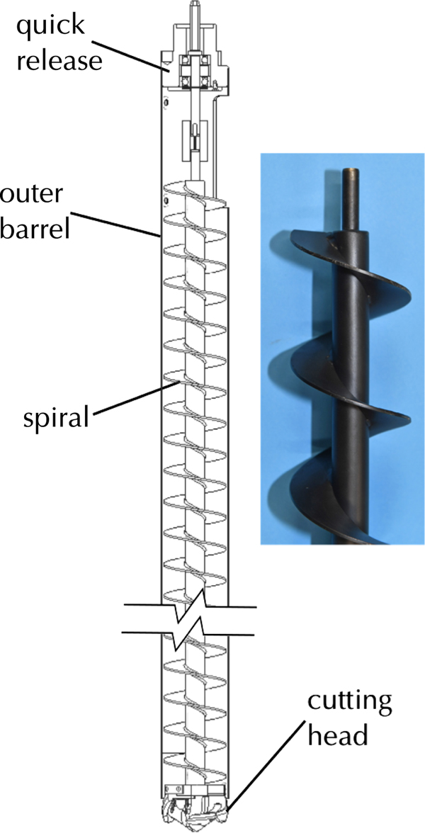
In agricultural machinery, a standard pitch auger is the one whose pitch is approximately equal to the outside diameter of the helicoidal flighting. Generally, the pitch is not less than 0.9 and not more than 1.5 times the outside diameter (ASABE Standards, 2006). Considering the torque carrying capability of the powered shaft and the performance of transporting ice cuttings, the outer barrel was chosen to be the driven shaft, and the enclosed inner auger is kept stationary. The outer rotating barrel pushes ice cuttings longitudinally along the inner auger, which makes the friction coefficient of ice cuttings against outer barrel and auger surface play a key role on the transportation efficiency (Talalay, Reference Talalay2003). Thus, the auger was specially coated with Xylan to decrease the transportation resistance. Fig. 4 shows the design of barrel section of the BAS RAID and Table. A1 gives its specifications. It turns out that the outer barrel rotating mechanism drilled better, faster and more consistently than the conventional auger in the field test season (2015/16) at Sky Blu and that the coated auger greatly benefits the ice cuttings transportation in the field season (2017/18) at Little Dome C (see supplementary file S1 for details). Usually with a non-rotating outer barrel anti-torque can be provided manually by gripping the barrel, when the anti-torque section is above the surface. This is not possible with the outer rotating barrel and once the decision to use this configuration, a short barrel was also designed. This short barrel is used for the first 7–8 m of drilling after which the anti-torque section will be sufficiently below the surface. The short barrel allows the anti-torque and motor sections to be manually held at the surface.
Barrel section. For clarity a shortened barrel is shown. Note that as we have chosen to retain right-handed cutters the outer barrel rotates clockwise when looking from above, we therefore need a left-handed static spiral to ensure that chipping transport is up the barrel. The Long barrel (4.48 m) is identical to the short barrel (1.6 m) except longer. A small section of an actual spiral with the black Xylan coating is also shown inset.

2.1.4. Cutters and cutter head
In order to develop the BAS RAID ice cutters a number of off-the-shelf drill bit designs were considered. These included HSS metal drill bits, flat wood spade bits, wood auger bits, forstener bits and an ice auger designed for ice fishing. These were tested in our cold rooms with an instrumented ice bucket that allowed measurement of the Weight-On-Bit (WOB) and the torque required to drill the hole. The ice auger, a lazer style design rather than a chipper design with two cutters was found to be the fastest and require the least torque and WOB for a given diameter. The cutter design and the head for mounting the cutters on was based on this. Our cutter is however smaller than any off the shelf ice auger, so custom cutters were made from A2 tool steel and hardened to 58 on the Rockwell C scale. The lazer cutters have a complex curved face which cannot be sharpened easily with flat sharpening stones, however, it was found that they could be sharpened with a Dremel fitted with a small felt polishing wheel and metal polishing compound.
The cutters are mounted to the head with two short cap head screws. The head in turn in mounted to a cutting head retaining ring which is secured to the outer barrel. This retaining ring also incorporates a flanged plain bearing which centres the stationary spiral at the lower end of the barrel (see Fig. 5).
Cutters and Cutter head.
2.2. The drill controller
With the motor controller housed in the motor section of the drill sonde, the drill controller can be extremely simple, with the only requirement being for CAN Bus communications to the motor controller. The drill controller also houses the high voltage power supply providing the 375 VDC to the drill. The drill controller is programmed to provide commands to the motor controller to set the motor running at a constant set speed either clockwise or counter-clockwise. The motor controller is programmed to return data when it receives a CAN sync command. The data returned are, the motor speed, motor torque, motor winding temperature, motor current and the motor controller PCB temperature.
An off-the-shelf development application board for a micro-controller which included a 5.7 inch resistive touch screen was chosen as this provided all the required capability. All information is displayed and can be controlled via the touch screen however large external switches and a potentiometer for speed control are provided for easy control while wearing gloves. Drill rpm and torque values are also shown on analogue displays in case the touch screen freezes, although this did not happen even at the low temperatures experienced outside at Little Dome C. The application board also provides a micro SD card where all the drilling data is logged every second.
An RS-232 input from the winch controller is provided so that the winch data are also logged by the drill controller every second. The winch data (winch speed, wire out and load) is also mirrored on the drill controller screen so that all the important information is displayed together.
Although acquisition rates for the motor data are ~10 Hz, data are only logged each second to a micro SD card. This logged data are: date and time, motor speed, motor torque, motor current, motor controller PCB temperature, motor winding temperature, motor controller statusword, drill controller internal temperature, drill controller external temperature winch speed, winch wire out, winch logged depth (this is the last ‘locked’ depth, see winch section below), and winch load.
2.3. The winch system
The lightweight winch system was designed and produced, from a specification provided by BAS, by MacArtney A/S in Denmark and is adapted from their Mermac family of winches. Adaptations included adding ski assembly for easy movement on the snow surface and the design of a mast with its highest point at 9.9 m above the snow surface.
2.3.1. The cable
Having decided to use a brushless DC motor in the drill sonde, the length of the cable requires that the motor controller is within the sonde. The disadvantage of this is that communication from the topside drill controller is required to control the drill motor. The simplest electronic implementation will use separate conductors for power and communications which results in a minimum of five conductors (two for power and three for communications), without resorting to using the armour as a conductor. The smallest off-the-shelf multiconductor cable, available from Rochester Cable was chosen. This has seven (24 AWG) conductors and is doubly armoured with galvanised steel, resulting in a cable with an outer diameter of 6.35 mm. We use four conductors for power and three for CAN Bus communications to the motor controller. The voltage rating for each conductor is 500 V and the breaking strength of the cable is 25.8 kN.
2.3.2. The winch
The winch uses a 2.2 kW single phase motor and includes an encoder on the motor and an encoder on the cable drum. This allows both the fine low-speed drilling and the high-speed tripping to be well controlled. The motor is mounted vertically and a lever arm to the load cell allows all sensing to be carried out on the winch itself. This makes set-up very fast but relies on the winch controller knowing how much cable has been paid out and which layer the winch is operating on. The winch is always spooled with cable and weighs 191 kg. The winch is capable of winching at >60 m min−1 on the lowest layer and can reach a speed of >80 m min−1 on the upper layer. It has a safe working load of 175 kg.
2.3.3. The winch controller
The winch controller was provided by MacArtney A/S to a specification provided by BAS. Programming of the controller makes the drilling operation as simple as possible and allows automated deployment, drilling and recovery of the drill sonde. This is all controlled by a Mitsubishi Programmable Logic Controller (PLC) operating a Schneider Electric variable speed drive.
A single axis joystick with a mechanical zero position interlock is used to control the winch manually and was found to provide very good intuitive control. Releasing the joystick immediately stops the winch. Holding the joystick can be tiring if the manual operation is required for a long time.
Automatic modes are controlled by the following momentary push button switches:
1. Auto Down – Automatic deployment of the sonde. Pressing this button sends the sonde down the borehole, at the specified winching speed and stops a programmed distance from the last ‘locked’ position.
2. Auto Up – Automatic retrieval of the sonde. Pressing this button sends the sonde up the borehole, at the specified winching speed and stops a programmed distance from the zero position.
3. Auto Drill – Automatic drilling mode. Pressing this button deploys the sonde down a specified distance at the specified drilling rate.
4. Lock Depth – Pressing this button sets the ‘locked’ depth and tells the winch where to return the drill next time the Auto Down button is pressed. This is pressed after a drilling run and the Auto Up light flashes to confirm the depth has been locked.
5. Zero Depth – Pressing this button sets the zero depth.
Two spring return selector switches are used to adjust the winching speed and the drilling speeds. All other settings are adjusted directly on the PLC. A photo of the winch controller is included in supplementary file S1.
The winch controller outputs all winch data via RS-232, which includes cable speed, wire out, locked depth and load.
2.3.4. The mast
As the winch includes two encoders and the load cell this enables the mast to be dumb. Once again the mast was designed to fit into the cargo bay of a Twin Otter and splits into two pieces. The two halves are easily assembled using two M20 nuts and bolts. The sheave wheel is then attached to the top with four M12 nuts and bolts. The mast is connected to the winch by a single M24 bolt which also forms the hinge about which the mast rotates when it is erected. The height of the top of the sheave wheel is 9.9 m above the surface of the snow. The mast weights 52 kg.
3. PERFORMANCE IN THE FIELD
The BAS RAID was deployed to Antarctica for four separate summer seasons. The first two were test seasons and took place at BAS's summer logistics hub at Sky Blu. The second two were science seasons in the Little Dome C (LDC) area as part of the Beyond Epica Oldest Ice project. Details of the experiences in the field, including aims, conclusions and modifications carried out based on the lessons learned for each of the four seasons is detailed in the supplementary file S1.
A total of seven boreholes were drilled to varying depths as summarised in Table 2.
Summary of BAS RAID performance in the field
The four separate seasons have allowed a number of changes to be made that improved the performance of the drill and the experience allowed the BAS RAID to reach its potential. The main lessons learned in and detailed in supplementary file S1 are:
1. Plastic spirals, although low friction are not strong enough if the ice chippings sinter.
2. The pitch of the spiral is critical.
3. The coefficient of friction on the spiral is very important and a low friction coating greatly reduces the transportation power required.
4. It is better to have an oversized motor as this solves a lot of problems especially if the barrel is over packed with chippings.
A great deal of learning how to operate the drill efficiently also took place. It was found early in the first season, that no cover was required on the opening at the top of the barrel. Very few chips seemed to be ejected out of the opening, which may be because of our unconventional outer rotating barrel. Knowing when to stop drilling could not always be judged solely from the motor torque measurement and if the current did spike the barrel was normally over-packed. An over-packed drill then took more time to empty and clear. It was better to stop at a set depth and the level of the chippings at the opening at the top of the barrel assessed as the drill was rising out of the borehole. If the opening was full then the set length would be reduced. If the set length was correct then the chippings would be visible in the opening but not full indicating that we were filling the barrel but not to the point of over-packing. The automatic winching modes performed very well and were very valuable in allowing the driller to concentrate on the drill but also allowed the driller to help with the chipping sampling process. The automation also allowed long operating shifts without mistakes being made even at high altitude at Little Dome C. The sharpness of the cutters makes a big difference as expected and these were changed for re-sharpened cutters at the end of every day.
The most successful season was the 2017/18 season at the LDC RAID2 site. During the 104.1 hours of drilling a depth of 461.58 m was reached, a new record for dry hole drilled by an electromechanical drill. 1706 bags of chippings were collected at an average spacing of ≈27 cm for water isotope analysis. A further 1073 chipping samples were collected for cosmogenic analysis. A Distributed Temperature Sensing cable as well as a thermistor string was deployed into the borehole in order to measure the temperature profile of the upper section of the ice sheet. This temperature profile is being remeasured in the 2018/19 season as the measurements had not fully converged during the limited time allowed at the end of the drill season. An estimate of the geothermal heat flux has been obtained but the new measurements are expected to produce a more reliable result. Although the target depth of 600 m was not reached, all the scientific aims of the drill have been met.
Figure 6 shows plots of borehole depth versus run number as well as run length versus run number. The upper plot should remove the quadratic winching component from Eqn (1). For a plot of wire out versus time see supplementary file S1 (Fig. S6). It can be clearly seen in the upper plot the change from the short barrel to the long barrel at just over 11 m. There is also a slight flattening of the plot at run number 220. After 2 weeks waiting a new surface power supply was used and three slow runs where little drilling was done were carried out in case there had been significant borehole closure. Having determined that the borehole had not closed up, full production drilling resumed. The lower plot shows once again the use of the short barrel initially. The plot also shows the ice density increasing resulting in shorter runs as the borehole gets deeper. After ≈200 m the density is no longer changing significantly and the run length becomes nearly constant.
Plots of borehole depth and run length versus run number.

Daily production is shown in Table 3. The small number of drilling hours on day 7 and on day 10 are due to high voltage power supply failure and the stuck drill respectively (see supplementary material file S1 for details). As can be seen daily progress is high (>40 m at over 400 depth) even though only one shift, usually with two operators, of ≈10 hours is taking place.
Table showing daily progress and drilling time for LDC RAID2 site

4. DISCUSSION & CONCLUSIONS
4.1. Power calculations
Table 4 shows the theoretical power requirement for the BAS RAID, with a cutter speed of 115 rpm and 0.35 m min−1 ROP, compared with two typical runs (runs 344 and 345 also shown in Fig. 7) with almost the same cutter speed and ROP (118 rpm and 0.44 m min−1). The power requirement is split in the power required for ice cutting, rotating the barrel and ice chipping transportation. These power measurements can be extracted by looking closely at the power data in each run. The N r component is the power required with no ice cutting or transportation (i.e. before the cutters have touched the ice at the beginning of the run). The cutting component of the power, N c, can then be deduced, as this is the step in the power measurement when the cutters just touch the bottom of the borehole, but while little chipping transportation is occurring. The total power, (N s) can be extracted from the final power at the end of the drilling run and hence, using Eqn (2), the transportation component (N t) can be evaluated. From Table 4, it can clearly be seen that the total power (N s) required is almost the same for both the theoretical and measured data, however the theoretical cutting power (N c) is much larger than the measured cutting power. Likewise the theoretical power required for ice chipping transportation (N t) is much lower than the measured power. We can conclude that the new type of drill, the BAS RAID, has a different power distribution diagram compared with classic electromechanical coring auger drills described by Talalay (Reference Talalay2003). More experiments should be carried out to improve the theory for full section drilling and long auger electromechanical drills.
Figure showing data for two typical runs. These were runs 344 and 345 which reached a depth of 400 m and 401 m, respectively.

4.2. Conclusions
A new class of electromechanical ice drill has been successfully designed, built, tested and operated. Rather than collect an ice core the drill performs dry, full diameter drilling and collects the chippings for analysis. This allows the winch to geared for high speed instead of needing a high pull force to break the core. When on the surface the drill motor can simply be reversed, ejecting the chippings for collection, without having to be brought down to the horizontal. A number of lessons were learnt, during two test seasons at Sky Blu and two scientific seasons in the Little Dome C region close to Dome Concordia. These lead to improvements in the drill and in the 2017/18 season, at the Little Dome C RAID2 site, a record depth of 461.58 m was drilled in just over 104 hours. At this depth the drill became stuck, however the scientific goals were reached.
Measured versus theoretical motor power
5. AMBITIONS
A number of future BAS RAID drilling seasons are planned. The next season will be at Sherman Island in the 2019/20 Antarctic summer where it is estimated that the ice is 420 m thick. Ice chippings will be collected and the borehole temperature profile will be measured in order to obtain a measurement of the geothermal heat flux. The final modifications to the drill will be tested.
Once the BAS RAID has drilled through the ice sheet obtaining subglacial rock samples is a high priority. Approximately 99.8% of Antarctica is covered in ice (Burton-Johnson and others, Reference Burton-Johnson, Black, Fretwell and Kaluza-Gilbert2016) and obtaining rock samples will add to the geological understanding of the continent, furthermore cosmogenic dating of the rock samples will allow previous ice-sheet retreat and expansion to be revealed. A percussive drill head is being designed to be fitted to the BAS RAID for this purpose.
The BAS RAID does allow chipping samples to be collected and those collected at Little Dome C are being analysed. These isotope results will be used to get an age-depth profile and a palaeoaccumulation record. Borehole loggers that would allow in-situ measurements have the potential for rapidly dating of the ice sheet. The most promising and best suited to the BAS RAID would be a down borehole dielectric profiler, which may allow matching to other previously dated ice core records. This logger would be in addition to the borehole temperature logging tools that are currently deployed in BAS RAID drilled holes.
With the success of the BAS RAID a larger version has been requested in order to drill access holes to shallower depths (≈200 m). This BigRAID would produce a borehole diameter close to 230 mm and work is being carried out on this design. It is also hoped that the whole drilling process might be automated. Applications include producing pilot holes for other drills and producing access holes for instrumentation.
SUPPLEMENTARY MATERIAL
The supplementary material for this article can be found at https://doi.org/10.1017/jog.2019.9
6. ACKNOWLEDGEMENTS
We would like to thank Jack Triest for helping develop the concept. Keith Makinson who was always on hand to review the design and suggest improvements. Rebecca Tuckwell for help in the field during test season 1 at Sky Blu, Fabrizio Frascatti, Michele Scalet, Saverio Panichi, Catherine Ritz and Massimo Frezzotti for help during the two seasons at Little Dome C. Special thanks must also go to Scott Polfrey and Andy Tait who were on hand to help when components did not fit.
APPENDIX A. DRILL SPECIFICATIONS & TABLES
RAID mechanical specifications

Main electronic components

Structural parameters and coefficients chosen to calculate the power according to Talalay (2003)


 Open access