


1. Introduction
In response to escalating environmental challenges such as climate change, resource depletion, and pollution, sustainable product design has become a strategic imperative. Ecodesign offers a promising solution by embedding environmental considerations throughout the product lifecycle without compromising performance or aesthetics (Reference Brezet and van HemelBrezet & van Hemel, 1997). This approach is gaining traction amid increasing regulatory demands—such as the European Union’s Ecodesign for Sustainable Products Regulation (ESPR) (Council Regulation (EU) 2024/1781)—and growing market pressure to differentiate through sustainability.
Beyond compliance, ecodesign presents a compelling business case. Companies adopting environmentally conscious design and manufacturing practices benefit from enhanced brand reputation, stronger stakeholder engagement, and improved operational efficiency (Reference Plouffe, Lanoie, Berneman and VernierPlouffe et al., 2011; Reference Staniszewska, Klimecka-Tatar and ObrechtStaniszewska et al., 2020). By minimizing waste and environmental impact, ecodesign contributes to competitive product development and supports long-term market success (Reference Wungkana, Siagian and TarigaWungkana et al., 2023).
Despite its advantages, ecodesign implementation remains challenging. Organizations often struggle with aligning sustainability goals with profitability, managing design trade-offs, and integrating new methodologies into established workflows (Reference Schöggl, Baumgartner, O’Reilly, Bouchouireb and GöranssonSchöggl et al., 2024). Designers are required to adopt unfamiliar tools and processes, which can disrupt existing practices and demand significant organizational change (Reference Dekoninck, Domingo, O’Hare, Pigosso, Reyes and TroussierDekoninck et al., 2016).
This tension is exemplified by a leading Dutch defence company, specializing in radar system technology, where this study was carried out. As a major industry supplier, they are increasingly committed to environmental responsibility and recognizes the strategic value of ecodesign (Reference Staniszewska, Klimecka-Tatar and ObrechtStaniszewska et al., 2020; Reference Wungkana, Siagian and TarigaWungkana et al., 2023). However, translating high-level environmental objectives into actionable engineering practices has proven difficult. Engineering teams often prioritize performance and functionality—especially in defence systems—leaving environmental considerations underrepresented in early design phases.
To address this integration gap, The company has identified Model-Based Systems Engineering (MBSE) as a potential enabler. MBSE offers structured capabilities to incorporate environmental goals into engineering workflows by leveraging system architecture and performance modeling. Yet, the integration of MBSE and ecodesign remains underdeveloped, as environmental requirements are typically non-functional and not explicitly supported in current MBSE frameworks (Reference Bougain and GerhardBougain & Gerhard, 2017).
This research responds to the company’s need for a standardized ecodesign approach that leverages MBSE to bridge the gap between strategic environmental incentives and practical engineering activities. The central research question is: How can MBSE-enabled capabilities be used to mitigate the gap between the company’s high-level ecodesign incentives and tangible engineering practices?
To answer this, the study develops an MBSE-driven ecodesign approach tailored to early product development phases. The approach includes an ecodesign analysis that identifies key architectural elements for improvement based on functionality and carbon footprint, using MBSE information models to link system architecture with environmental performance. Applied to an existing radar system, the approach demonstrates both relevance and practicality, with potential for broader application across similar product redesign efforts.
2. Product development and ecodesign integration needs
Systems engineering is a foundational discipline, reflecting the complexity of the company’s solutions. The product development process follows a structured process, which forms the basis into which ecodesign activities must be effectively integrated.
To support this process, the orginisation employs MBSE using Capella (Reference RoquesRoques, 2017), a modeling tool based on the ARCADIA methodology (Reference VoirinVoirin, 2017). ARCADIA structures system development across four layers: Operational Analysis, System Analysis, Logical Architecture, and Physical Architecture. These layers align with the organisation’s development phases (Figure 1), enabling a consistent and traceable flow from stakeholder needs to system implementation. Capella models serve as a shared reference across teams, capturing requirements, system behavior, and design decisions.
Internal development phases aligned with the ARCADIA methodology

Despite this robust engineering framework, the company faces challenges in embedding environmental considerations into its development process. Although the company has committed to reducing greenhouse gas emissions and set strategic ecodesign targets, these goals have not yet translated into standardized engineering practices. A recent pilot case revealed that ecodesign efforts remain fragmented and lack integration with existing MBSE workflows, limiting their effectiveness and scalability. A well-integrated ecodesign approach will not only support the organisation’s sustainability goals but also enhance the company’s ability to innovate responsibly within its established systems engineering framework.
To address this gap, a structured ecodesign approach is required that: (1) builds on its current MBSE capabilities to ensure traceability and consistency by utilizing Capella model information; (2) transforms strategic directives into engineering activities, thus bridging high-level environmental objectives with practical workflows, ensuring compatibility with existing methodologies and carbon footprint reporting standards while providing clear implementation guidance; (3) highlights architectural areas for environmental improvement, thus helping engineers identify effective improvement strategies and generate viable technical solutions; (4) supports early-stage decision-making without overwhelming complexity.
3. Literature review
Adapting ecodesign to organizational and system contexts requires strategies that reflect company maturity and build upon existing practices (Reference Pigosso, Rozenfeld and McAloonePigosso et al., 2013). A thorough understanding of the product lifecycle’s carbon footprint is essential for identifying the most impactful phases for intervention (Reference He, Liu, Zeng, Wang, Zhang and YuHe et al., 2019; Reference Pigosso, Zanette, Filho, Ometto and RozenfeldPigosso et al., 2010; Reference Santolaya, Lacasa, Biedermann and MuñozSantolaya et al., 2019; Reference Seow, Goffin, Rahimifard and WoolleySeow et al., 2016). Standardized methodologies further support consistency and scalability across diverse engineering domains (Reference Lacasa, Santolaya and BiedermannLacasa et al., 2016).
Various tools have been proposed to facilitate ecodesign in early development stages. Among these, checklists offer simplicity but depend heavily on expert judgment, while Quality Function Deployment (QFD) enables structured integration of customer and environmental requirements, albeit with increased complexity and time demands. Life Cycle Assessment (LCA) provides quantitative evaluations but is constrained by data availability and its assessment-oriented nature, which limits direct design applicability (Reference Ramani, Ramanujan, Bernstein, Zhao, Sutherland, Handwerker, Choi, Kim and ThurstonRamani et al., 2010).
MBSE presents promising avenues for supporting ecodesign, with two primary integration strategies emerging in the literature (Reference Bougain and GerhardBougain & Gerhard, 2017; Reference Eigner, Dickopf and ApostolovEigner et al., 2017). One approach involves direct modeling of environmental aspects using SysML, while the other leverages system behavior analysis for environmental assessment. Both methods enable the extraction of architectural data to evaluate energy consumption and carbon footprint, helping engineers identify high-impact components for redesign. However, challenges remain, including tool interoperability, the complexity of multi-parameter assessments, and integration with data management systems.
Effective ecodesign also hinges on informed decision-making that balances environmental objectives with functional and stakeholder requirements (Reference Pigosso, Rozenfeld and McAloonePigosso et al., 2013). Multi-criteria decision-making frameworks are essential for evaluating trade-offs between environmental and economic impacts (Reference Romli, Prickett, Setchi and SoeRomli et al., 2015), while standardized indicators support quantifiable assessments that guide design choices (Reference Lacasa, Santolaya and BiedermannLacasa et al., 2016).
Despite its potential, integrating ecodesign into early development phases remains difficult due to the complexity of environmental assessments, limited data availability, and integration barriers (Reference Favi, Campi, Germani and ManieriFavi et al., 2018; Reference Ramani, Ramanujan, Bernstein, Zhao, Sutherland, Handwerker, Choi, Kim and ThurstonRamani et al., 2010; Reference Romli, Prickett, Setchi and SoeRomli et al., 2015). Literature commonly addresses three approaches: environmental analysis of products, development of ecodesign solutions, and combined environmental and technical strategies (Reference He, Liu, Zeng, Wang, Zhang and YuHe et al., 2019; Reference Lacasa, Santolaya and BiedermannLacasa et al., 2016; Reference Pigosso, Zanette, Filho, Ometto and RozenfeldPigosso et al., 2010; Reference Romli, Prickett, Setchi and SoeRomli et al., 2015; Reference Santolaya, Lacasa, Biedermann and MuñozSantolaya et al., 2019; Reference Seow, Goffin, Rahimifard and WoolleySeow et al., 2016). A general workflow emerges, beginning with carbon footprint analysis, followed by identification of impactful lifecycle stages, scope definition, component targeting, development of improvement strategies, implementation, and impact evaluation (Figure 2).
Literature-inspired ecodesign workflow for the early stages of product development

4. Proposed ecodesign approach
Driven by the company’s needs and inspired by the literature, the proposed ecodesign approach is an update from the current set of ecodesign activities performed, and which introduces two new key activities (A.3 and A.4) into the orient phase of its existing ecodesign development process centred on system redesign (Figure 3). The adapted approach puts greater emphasis on identifying so-called environmental hotspots in the systems architecture, allowing engineering teams to narrow down their focus to orient on specific ecodesign opportunities.
MBSE provides necessary information for identifying architectural hotspots through Capella model integration into the approach. The system information available in the Capella models are leveraged to introduce functional and hierarchical data into the ecodesign decision-making process, beyond just the carbon footprint. The Capella models enable this approach since the entire functional link between system capabilities and component specifications can be traced through the MBSE models layers.
Positioning of the proposed ecodesign approach improvement within existing ecodesign activities

Figure 3 Long description
The flowchart illustrates the stages of an ecodesign approach improvement within existing ecodesign activities. The process is divided into three main phases: Requirements & Needs Analysis, Orient, Design, and Develop. Each phase contains several steps represented by circles labeled A.1 to A.9. The steps are as follows: A.1 Engage customers to contribute to ecodesign ambitions, A.2 Determine the main environmental stakes of the solution, A.3 Identify ecodesign hotspots in the system's architecture, A.4 Derive ecodesign opportunities based on the ecodesign hotspots, A.5 Define strategic ecodesign orientations, A.6 Perform impact assessment of hardware and software architecture options, A.7 Formalize ecodesign solutions into design requirements, A.8 Refine the solution's ecodesign requirements to lower level requirements, and A.9 Consolidate the solution against ecodesign targets. The flowchart shows the progression from one step to the next, indicating a sequential process with arrows connecting each step. The phases are color-coded: Requirements & Needs Analysis in yellow, Orient in blue, Design in green, and Develop in red.
In more detail, the proposed ecodesign approach is composed by 10 steps in the orient phase of product development (Figure 4), which also guarantee a smooth interface with preexisting activities (A.2 and A.5) and the connection to the MBSE models. The steps highlight how Capella models are used as an information source for the ecodesign approach to identify ecodesign hotspots and derive ecodesign opportunities. In the next section, the steps are further described through a case of application.
Steps from the proposed ecodesign approach

5. Case of application
The aim of this study is to demonstrate the practical application and validate the effectiveness of the proposed ecodesign approach by implementing it on an existing radar product. The product chosen for this case of application, was a mature and significant Radar product within the company’s portfolio. Its selection was strategic, as a previous, more exploratory ecodesign pilot study had been conducted on this system, providing a baseline for comparing the results and effectiveness of this newly proposed, more structured approach. The application of the ecodesign methodology followed the ten steps defined in the approach (Figure 4), beginning with a high-level assessment and progressively narrowing down to the component level to identify targeted areas for improvement.
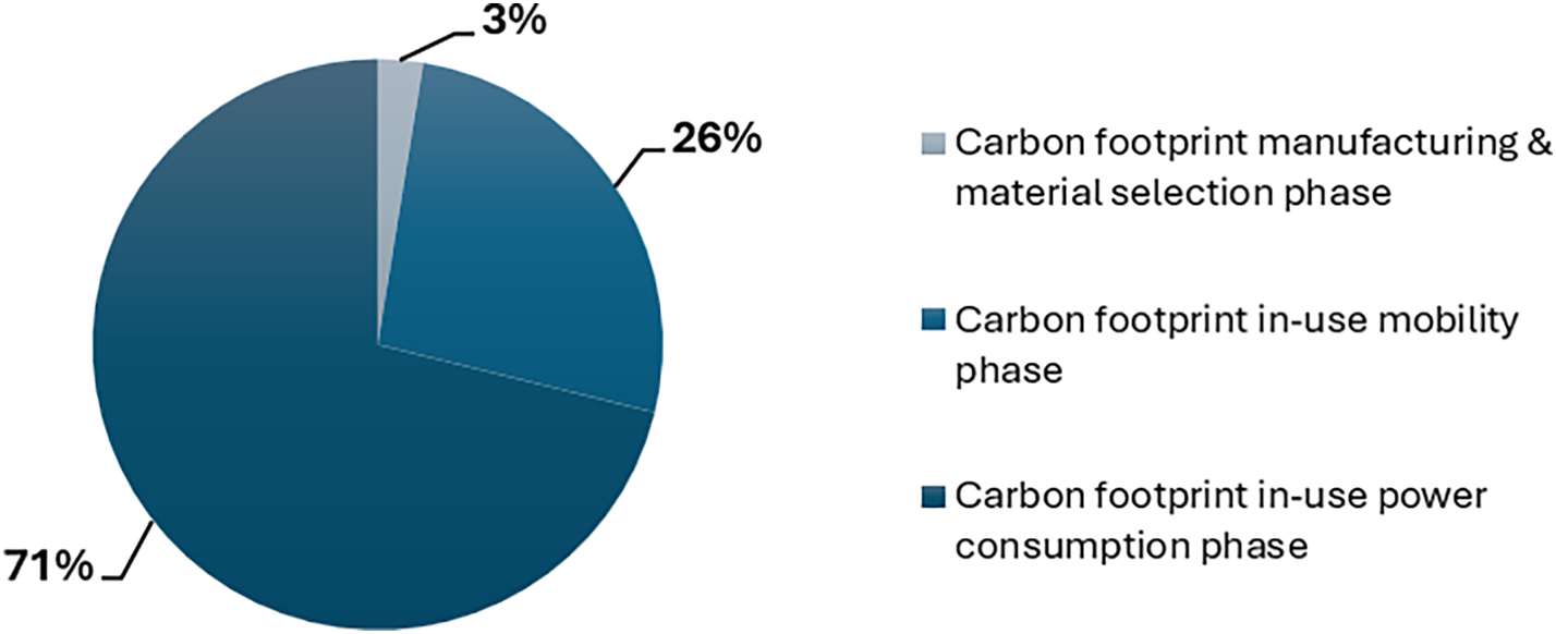
Steps 1 & 2 determine the main environmental stakes of the system. This high-level analysis is crucial as it sets the scope and focus for the more detailed component-level analysis that follows. The total lifecycle carbon footprint of the Radar was calculated to be 1041 tonnes of CO2-equivalent, and the analysis of the lifecycle breakdown revealed that the Manufacturing and Use phases were the most significant contributors to the overall environmental impact (Figure 5).
Lifecycle carbon footprint of the radar system

Therefore, to ensure that engineering and design efforts are concentrated where they can achieve the greatest environmental benefit, the remainder of the detailed analysis would focus exclusively on these two lifecycle stages. Additionally, the Use phase consisted of two separate phases, one for the in-use power consumption of the radar, and one for that accounts for the carbon emissions of the transporting vessel due to the mass of the radar, which is captured in in-use mobility.
This step also served to define the specific technical parameters that would need to be assembled for each component to accurately calculate their respective carbon footprints within these significant lifecycle stages. These parameters included mass, materials, average component lifespan, mean power consumption, and operational duty cycle.
Step 3 involves extracting and assembling all the required technical and functional data for every component within the Radar system architecture. This data collection phase is fundamental, as the quality and completeness of the data directly influence the accuracy of the subsequent hotspot analysis. Two primary categories of data were assembled: functional and architectural information, and technical component specifications. The former were extracted from the system’s MBSE architecture models and included data about Physical components (P), Physical Functions (PF), and Capability Realizations (CR). In other words, a complete list of physical components, their hierarchical relationships, the specific functions each component performs, and their contribution to the overall system capabilities.
The latter was extracted from the product lifecycle management (PLM) system, and included, for each relevant component in the system hierarchy, technical parameters such as; mass, material composition, lifespan, mean power consumption, and operational duty cycle. This dataset provides the quantitative basis needed to calculate the carbon footprint of each individual component.
During step 4, the lifecycle carbon footprint for each individual component from the Radar are calculated, focusing solely on the Manufacturing and Use phase. This granular level of analysis represents a significant advancement over previous system-level assessments, providing much more detailed and actionable insights into the main sources of environmental impact. The initial results of this component-level calculation provided a clear breakdown of the carbon footprint among the major subsystems of the radar. The analysis showed that the Cooling Cabinet, the Director, the Control Cabinet (CC), and the Air Dryer were the most emissive high-level subsystems in the system (Figure 6). This finding offered an early, high-level indication of where potential ecodesign improvements would be most effective.
A more detailed examination of the carbon footprint breakdown across the different lifecycle stages yielded to the identification that the Manufacturing phase contributed marginally to the total lifecycle carbon footprint. This result directed the focus to the Use phase, particularly towards improving energy efficiency and reducing weight rather than focusing solely on manufacturing processes or materials.
Carbon footprint breakdown of major subsystems

Step 5 incorporates a key innovative aspect of the proposed ecodesign approach, which is the ability to trace the calculated carbon footprint of individual components (P) to the system capabilities (CR) they enable. The link between components and the capabilities they contribute to is inherently enabled by the traceability within the MBSE models in Capella. By linking environmental impact to functionality, this step helps to identify which capabilities are “expensive” from a carbon footprint perspective.
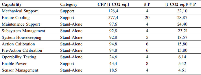
To achieve this, the carbon footprint of each capability was calculated based on the combined footprints of all components contributing to it, disregarding the amount of time a component would effectively contribute to each capability. Table 1 illustrates the analysis results by showing the 10 most impactful capabilities.
Support Capabilities were identified as the most inefficient. In particular, the Mechanical Support and Ensure Cooling capabilities showed a very high carbon footprint per involved component. This is logical, as these capabilities are fundamental to the operation of the entire system and often involve heavy or power-intensive components.
Stand-Alone capabilities, such as Maintenance Support, Subsystem Management, and System Housekeeping, also appeared at the top of the list as significant contributors. A possible explanation for this, is that the components realizing these capabilities are often dedicated and share little functionality with other parts of the system, leading to a high environmental cost for a selective function.
This capability-centric analysis provided an additional layer of insight, complementing the component-level data. It successfully highlighted specific functional areas of the system that warrant closer inspection from an ecodesign perspective, providing a strong indication of where to look for hotspot components in the subsequent step.
Carbon footprint per capability

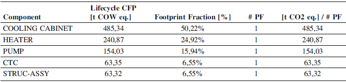
Step 6 represents the core of the analysis, where ecodesign hotspots components with disproportionately high environmental impact relative to their functional contribution are identified. The methodology for identifying these hotspots relies on a straightforward but powerful metric: an index calculated by relating a component’s total lifecycle carbon footprint to the number of functions (PF) it performs. This provides a normalized measure of environmental impact per function, effectively pinpointing components that are functionally inefficient.
By applying this metric and ranking all components in the system’s architecture, a clear list of the most inefficient components emerged. The results of the ecodesign hotspot analysis are shown partially in Table 2. The Cooling Cabinet was identified as the single most inefficient component in the entire system, with an extremely high carbon footprint for the single function it performs. Two of the Cooling Cabinet’s key sub-components, the Heater and the Pump, also ranked at the very top of the list, confirming that the inefficiency of the parent assembly was driven by these specific parts.
Components with the highest carbon footprint per function

A filter was set for selecting the hotspots, where a component had to contribute at least 5% of the system’s total carbon footprint to be considered a primary hotspot. Applying this filter to the list of inefficient components and selecting only the lowest-level components in any given hierarchical branch, resulted in the final list of identified ecodesign hotspots for the radar system (Heater, Pump, CTC, and structural assembly). Note how the Cooling Cabinet subsystem itself was not selected, but only its inefficient components. This systematic identification process successfully narrowed down the entire complex system to just four key components that serve as the primary targets for deriving concrete ecodesign opportunities.
Step 7 has the objective of evaluating the hotspot components to confirm their suitability as targets for ecodesign improvements and to understand the broader impact of any potential changes. This evaluation considered the components’ functionality, their contribution to system capabilities, and their interdependencies within the system architecture. The analysis of the four hotspot components revealed important distinctions between them:
The CTC, upon closer inspection, was found to be a sub-assembly that contributes to 18 different system capabilities, even though it only performs a single central function. By considering the number of capabilities as well as number of functions, the CTC suddenly is not a clear ecodesign target candidate as highlighted by Table 3. This finding demonstrated the approach’s ability to look beyond initial metrics and refine its focus. Consequently, the CTC was deemed not to be a true hotspot and was eliminated from further consideration.
Hotspot component functions and contributions to capabilities, highlighting carbon footprint per function and capability

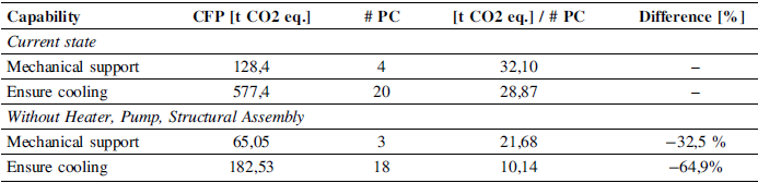
To prioritize among the remaining three, their relative impact on their respective capabilities was assessed. The results are shown in Table 4. The analysis showed that the Heater and the Pump had a far greater impact on the carbon footprint of the “Ensure Cooling” capability than the Structural Assembly had on the “Mechanical Support” capability. Modifying or removing the Heater and Pump would lead to a potential 64.9% reduction in the carbon footprint of the entire cooling capability, whereas the impact of changing the Structural Assembly was significantly lower at 32.5%.
This evaluation provided a clear and data-driven justification for the final selection. The Heater and the Pump were definitively chosen as the primary targets for deriving ecodesign opportunities. This decision was based not only on their high individual carbon footprints but also on their massive impact on a critical support capability and their close physical and functional relationship within the Cooling Cabinet subsystem, which presents more holistic improvement opportunities.
Hotspot components carbon footprint impact on their capabilities

Step 8 involves a detailed analysis of the two selected hotspot components, to derive specific opportunities for improvement. An examination of their lifecycle carbon footprint breakdown revealed a significant commonality. For both components, the In-use Power Consumption stage was by far the most significant contributor to their environmental impact. This was directly linked to their high operational duty cycles. Based on their operational characteristics, some opportunities were derived.
The analysis showed that the Heater’s high power consumption was based on a duty cycle in a worst-case scenario of continuous operation in a cold climate. In many real-world scenarios, it would need to be used far less intensively. The derived opportunity was therefore to optimize its power consumption profile according to the actual operational use case, for instance by improving system insulation to reduce the need for heating in a worst-case scenario.
The opportunity for the Pump was even more straightforward. The analysis revealed that the pump was significantly oversized for the radar’s actual cooling and heating needs, as it is a standardized component used across multiple radar systems within the product portfolio. Furthermore, it operated with only two modes (On or Off), making it highly inefficient. The opportunity thus lies by optimizing the power consumption profile of the pump to fit the actual demands of the radar system.
To finalize, steps 9 & 10 aimed to define specific ecodesign orientations based on the opportunities identified above. The ecodesign process has yielded three strategic orientations aimed at optimizing the radar system’s thermal management components.
First, downsizing both the pump and heater ensures that their physical dimensions align more closely with operational demands, enhancing system efficiency. By matching the actual cooling and heating needs of the system, the design combats over-engineering and avoids unnecessary energy use. Second, the heater’s excess capacity presents an opportunity to support multiple onboard systems, thereby maximizing its utility and reducing redundancy. Third, introducing variable power modes to the pump allows it to dynamically respond to changing cooling requirements, significantly lowering energy consumption.
6. Discussion
The application of the proposed ecodesign approach to the Radar system served as a successful validation of its effectiveness and utility in identifying and selecting target components for ecodesign. The results and the structured nature of the process itself provide a compelling argument for its value, particularly in an early-stage development context.
Together, the three strategic orientations form a robust, data-informed foundation for the next phase of detailed redesign. The ecodesign orientations warrant the need for impact assessment across the system, which will lead to new design requirements. By modelling these design requirements into the MBSE models, the approach provides the feedback into the engineering design domain. The ecodesign approach therefore effectively mitigates the gap from high-level incentives on ecodesign to engineering activities.
A key strength of the approach, as demonstrated in this case, is its ability to focus the analysis at the component level rather than the system level. This shift allows for a much more selective and efficient ecodesign assessment, ensuring that time and resources are not wasted on low-impact areas but are instead concentrated on the components with the most significant potential for improvement. By linking environmental data (carbon footprint) with functional data (functions and capabilities), the approach successfully identified true hotspots grounded in both engineering and environmental metrics. MBSE enabled the functional and hierarchical system data to be used in an environmental study, without having to use external databases and other assumptions.
The ultimate justification for the approach’s value comes from a comparison with a previous, more exploratory ecodesign pilot study conducted on the same Radar product. That earlier study had also identified the pump as a key component for improvement, but lacked a structured approach and the use of standardized data-driven metrics. The approach detailed here provided a more efficient, structured, and robust methodology for arriving at and justifying that same conclusion. Unlike the exploratory pilot, this data-driven approach streamlines the process, removes ambiguity, and provides clear, actionable recommendations that are directly linked to both lifecycle data and the system’s functional architecture. This comparison underscores the reliability and enhanced rigor of the proposed approach.
7. Conclusion
The developed ecodesign approach successfully addresses the fundamental challenge of translating high-level environmental incentives into actionable engineering practices within a defence organisation’s MBSE-enabled development process. Through systematic integration of literature findings and stakeholder requirements, the approach demonstrates how ecodesign can be embedded into existing engineering workflows without disrupting established practices, even in the development of highly complex systems, such as radars.
While the approach shows promise, its validation through a single case study limits generalizability. Future applications across diverse systems are needed to assess its broader applicability. Additionally, the lack of quantifiable metrics in later stages of the approach and limited stakeholder familiarity with MBSE-ecodesign integration suggest areas for refinement. Strengthening the connection to requirements engineering and expanding the approach to later development phases could enhance its impact. Furthermore, the hotspot identification metrics, while intentionally simple and effective for early stage screening, are sensitive to uncertainties in lifecycle inputs and depend on how functions are defined in the MBSE models. More robust metrics could be developed in the future.
Looking ahead, further research should explore the integration of ecodesign principles throughout the full product development process with MBSE, the development of company-wide system oriented environmental impact portfolios, and the use of MBSE for dynamic sustainability assessments during development. These directions will help evolve MBSE-driven ecodesign into a more comprehensive and adaptive framework that can be pursued further in industry.







 Open access

