

Introduction
The primate cerebral cortex consists of many anatomically and functionally distinct areas processing visual information (Felleman & Van Essen, Reference Felleman and Van Essen1991). Some of these areas, including the primary (V1) and secondary (V2) visual areas and the middle temporal (MT) area, have been described with precision in many primate species. However, there is still lack of consensus regarding the number, location, and exact boundaries of most other areas within extrastriate cortex in any primate species (Kaas, Reference Kaas, Rockland, Kaas and Peters1997; Rosa, Reference Rosa, Rockland, Kaas and Peters1997; Van Essen, Reference Van Essen, Chalupa and Werner2004; Rosa & Tweedale, Reference Rosa and Tweedale2005).
In this context, the organization of the cortex located along the anterior border of V2 [the “third-tier” visual cortex (Allman & Kaas, Reference Allman and Kaas1975)] has been a long-standing point of contention. Several conflicting partitioning models for this cortical region have been proposed over the years (for a review, see Angelucci & Rosa, Reference Angelucci and Rosa2015, in this special issue). There is now substantial agreement among most research groups on the concept that a complete third visual area (V3), representing both the upper and lower visual quadrants, directly borders V2 anteriorly. Specifically, there is general consensus that ventral V2 (V2v) is bordered anteriorly by a representation of the upper visual quadrant, which has been variably termed ventral V3 (V3v) (Zeki, Reference Zeki1971; Gattass et al., Reference Gattass, Sousa and Gross1988), ventral posterior area (VP; Newsome et al., Reference Newsome, Maunsell and Van Essen1986), or the ventral half of ventrolateral posterior area (VLP; Rosa & Manger, Reference Rosa and Manger2005). However, there remains disagreement regarding the exact location and extent of the lower visual field representation of V3/VP/VLP. According to one model, which we refer to as the “V3-only model”, this is located in the dorsal half of the third-tier cortex, forming an elongated and continuous strip of cortex along most of the anterior border of dorsal V2 (V2d), sharing with V2d the horizontal meridian (HM) representation at that border, and mirroring the retinotopy of V2d. According to this model, the dorsal part of the third tier cortex is, thus, largely occupied by the dorsal half of V3 (V3d) (Fig. 1A). This model was initially proposed for Old World macaque by Zeki and Cragg based on microelectrode mapping studies (Cragg, Reference Cragg1969; Zeki, Reference Zeki1969, Reference Zeki1977, Reference Zeki1978a; Zeki & Sandeman, Reference Zeki and Sandeman1976; Van Essen & Zeki, Reference Van Essen and Zeki1978), and later espoused by Lyon and Kaas (Reference Lyon and Kaas2001, Reference Lyon and Kaas2002a,Reference Lyon and Kaasb) on the basis of connectional studies in both Old and New World primates.
Three partitioning models proposed for the marmoset third-tier visual cortex. (A, B) Partitioning of marmoset visual cortex, according to each model, shown onto an outline of unfolded and flattened marmoset visual cortex. The thin dashed outline is the outline of the dorsolateral surface of visual cortex prior to unfolding, whereas the outer thin solid outline is the outline of unfolded medial and ventral cortex. Inset at bottom left: the diagram of the central 16° of the right visual hemifield. In the inset and panels (A–C), the thick dashed lines/contours represent the HM and the thick solid lines/contours represent the VM at areal boundaries. Thin solid contours demarcating areal borders indicate uncertainty of meridian representations. Stars: foveal representations. Thin dotted contours: iso-eccentricity lines (numbers indicate eccentricity in degrees). “+” and “-”: upper and lower visual quadrants, respectively. Regions representing the upper visual field are additionally shaded in gray (adapted from Jeffs et al., Reference Jeffs, Federer, Ichida and Angelucci2013 and Rosa et al., Reference Rosa, Palmer, Gamberini, Tweedale, Pinon and Bourne2005). (A) The “V3-only model”, according to which a single and continuous area V3 (pink) occupies most of the third-tier cortex, bordering V2 anteriorly. This is depicted according to the most recent proposal of this model in marmoset by Lyon and Kaas (Reference Lyon and Kaas2001). In this model, area DM (blue) is displaced anteriorly to V3, encompassing the territory of areas DM and DA of the “multiple-areas model” shown in panel (B). (B) The “multiple-areas model” according to which two distinct visual areas, DM (blue) and VLP (pink), both representing the upper and lower quadrants, border area V2 anteriorly. This model is depicted according to its most recent version proposed by Rosa et al. (Reference Rosa, Palmer, Gamberini, Tweedale, Pinon and Bourne2005). (C) The “split-V3 model” (as depicted in Rosa et al., Reference Rosa, Palmer, Gamberini, Tweedale, Pinon and Bourne2005), according to which area V3 (pink), representing the upper and lower quadrants abuts V2 anteriorly, but its lower quadrant representation is split into two patches by the interposition of the upper quadrant representation of DM (blue). The latter is marked by a “?” to indicate uncertainty regarding the identity of this improbable area missing a lower quadrant representation. Variants of this model include, the “pinched-V3 model” of Gattass et al. (Reference Gattass, Sousa and Gross1988; described in the Introduction), and the “incomplete-V3 model” proposed for the macaque by Van Essen and colleagues (Van Essen et al., Reference Van Essen, Newsome and Bixby1982, Reference Van Essen, Newsome, Maunsell and Bixby1986; Burkhalter et al., Reference Burkhalter, Felleman, Newsome and Van Essen1986; Felleman et al., Reference Felleman, Burkhalter and Van Essen1997) (based on connectional and functional asymmetries between V3d and V3v), according to which V3d and V3v are two different areas, i.e., V3 and VP, respectively. Abbreviations: DA: dorsoanterior area; DI: dorsointermediate area; DLc, DLr: caudal and rostral subdivisions of the dorsolateral area (thought to be the homologue of macaque area V4); DM: dorsomedial area; FST: fundus of the superior temporal sulcus area; IT: inferotemporal cortex; MT: middle temporal area; MTc: middle temporal crescent area; MST: medial superior temporal area; OPt: occipitoparietotemporal subfield of the ventral posterior parietal cortex (PPv); PP: posterior parietal cortex; PPd: dorsal subdivision of the posterior parietal cortex; PPl: lateral subdivision of the posterior parietal cortex; PPv: ventral subdivision of the posterior parietal cortex; VLA: ventrolateral anterior area; VLP: ventrolateral posterior area; V1: primary visual cortex; V1d: dorsal half of V1; V1v: ventral half of V1; V2: secondary visual area; V2d: dorsal half of V2; V2v: ventral half of V2; V3: third visual area; V3d: dorsal half of V3; V3v: ventral half of V3.

The V3-only model has, however, been challenged by microelectrode mapping data from New World primates. These data demonstrated an upper visual quadrant representation abutting some of the rostral border of V2d, thus occupying part of the territory ascribed to V3d in the V3-only model (Allman & Kaas, Reference Allman and Kaas1975, Reference Allman and Kaas1976; Weller et al., Reference Weller, Steele and Cusick1991; Krubitzer & Kaas, Reference Krubitzer and Kaas1993; Sereno et al., Reference Sereno, McDonald and Allman1994, Reference Sereno, McDonald and Allman2015; Rosa & Schmid, Reference Rosa and Schmid1995; Beck & Kaas, Reference Beck and Kaas1998; Rosa et al., Reference Rosa, Palmer, Gamberini, Tweedale, Pinon and Bourne2005). This upper visual field region was initially interpreted as part of a dorsomedial area (DM), whose lower visual quadrant representation was located just medial to the representation of the upper quadrant (Allman & Kaas, Reference Allman and Kaas1975; Rosa & Schmid, Reference Rosa and Schmid1995). In this model, which we refer to as “the multiple-areas model”, lower field V3 would be less extensive than in the V3-only model, occupying only the lateral portion of the dorsal aspect of the third-tier cortex (Fig. 1B). This modified V3 was mapped in detail in marmoset visual cortex, and renamed area VLP by Rosa & Tweedale (Reference Rosa and Tweedale2000). In the multiple-areas model, the dorsal aspect of the third-tier cortex is, thus, occupied by two areas: DM, medially, and lower quadrant VLP, laterally (Fig. 1B). While favoring this model as more parsimonious for preserving histological and retinotopic continuity within the proposed areas, Rosa et al. (Reference Rosa, Palmer, Gamberini, Tweedale, Pinon and Bourne2005) also offered an alternative interpretation of their microelectrode mapping data. The latter views V3d as discontinuous, i.e., split into two patches by an interposed region of upper field representation (Fig. 1C). This “split-V3 model” has also recently been proposed as a viable alternative to the V3-only model by Kaas et al. (Reference Kaas, Roe, Baldwin and Lyon2015, in this special issue), and resembles what Angelucci and Rosa (Reference Angelucci and Rosa2015) have termed “the pinched-V3 model” of Gattass et al. (Reference Gattass, Sousa and Gross1988), in which V3d becomes narrower at its mid-point (sometimes being almost divided into two portions).
Recently, using dense mapping of topographic patterns of corticocortical connections, we have provided additional evidence for the existence of an upper visual quadrant representation abutting V2d anteriorly (Fig. 2A), and bordered medially and laterally by cortical territories representing the lower visual quadrant (Fig. 2B) (Jeffs et al., Reference Jeffs, Federer, Ichida and Angelucci2013). These results, schematically illustrated in Fig. 2B, are consistent with both partitioning models shown in Fig. 1B and 1C; namely, the two lower field representations abutting V2d anteriorly could belong to two different visual areas, DM and VLP (as in Fig. 1B), or they could belong to a single area V3 (as in Fig. 1C).
Anatomical evidence from marmoset visual cortex for an upper quadrant and two lower quadrant representations bordering dorsal V2 anteriorly (based on data from Jeffs et al., Reference Jeffs, Federer, Ichida and Angelucci2013). Diagram of unfolded and flattened V1, V2 and third-tier visual cortex showing the location of injection sites (colored ovals with black outline) and of transported cell label (filled ovals); intra-areal label is omitted. Insets: visual field maps of the location of the injection sites (small circles) and transported label in V1 (shaded colored regions). (A) Evidence for an upper quadrant representation bordering V2d. Closely spaced injections of four different neuroanatomical tracers across the full width of upper field DM resulted in cell label in upper field V1 and V2 that progressed from these areas' HM representation (blue ovals resulting from the blue injection site) to their VM representation (red and green ovals arising from the red and green injection sites, respectively). This demonstrated that the injection sites resided in a region representing the upper quadrant. That this region abutted V2d, rather than V3d, was further demonstrated by the location of transported blue label at the HM representation of V1d, indicating that the injection site that produced it (blue) straddled the HM representation at the border between DM and lower field V2. Had the blue injection resided at the border between V3d and DM, which represents the VM, the resulting blue label would have, instead, resided at the lower VM representation of V1 (at the location of the blue arrow). While injections straddling the HM representation at the border between V2d and V3d, which represents the HM, would also produce label at the HM representation in both upper and lower field V1 and V2 (Jeffs et al., Reference Jeffs, Ichida, Federer and Angelucci2009), the progressively more anterior injections would be expected to produce label in lower, rather than upper field V1 and V2, had they resided in V3d. These data demonstrated that upper field DM directly abuts V2d without an interposed area V3. (B) Evidence for two patches of lower quadrant representation bordering V2d. Seven closely spaced injections of different tracers (only 3 are shown in the cartoon for clarity) were made across the full width of V2d, as demonstrated by the topography of transported label in V1d, which showed an orderly progression from the lower VM representation, at the border between V1d and V2d, to the HM representation in V1d. These tracer injections also produced two orderly progressions of transported label abutting V2d anteriorly (marked as 1 and 2), which were mirror reversals of the tracer injection site sequence. A third label reversal (marked as 3) was located well anterior (1.5 mm) to reversal 1, and its topography was consistent with the retinotopic organization of area DA demonstrated by Rosa and Schmid (Reference Rosa and Schmid1995). There was no evidence for a label reversal posterior to reversal 1.
Resolving the organization of the third-tier cortex is crucial for understanding its function and evolution. Therefore, to determine which of the two models depicted in Fig. 1B and 1C reflect the organization of the dorsal aspect of the third-tier cortex, we have investigated the patterns of inter-areal afferent connections arising from this cortical region. If the two lower field representations bordering V2d anteriorly are part of two different areas, DM and VLP, the inter-areal connections arising from them are expected to differ, while they are expected to be similar, if they arise from the same visual area, V3. Our results indicate that the dorsal aspect of the third-tier cortex consists of two distinct areas: a complete area DM, representing the full contralateral visual hemifield, and the lower quadrant representation of area VLP/V3.
Materials and methods
Animals
For this study, we chose the marmoset monkey (Callithrix jacchus), a diurnal New World primate with a well-developed fovea, since its lissencephalic cortex offers easy access to extrastriate cortical areas. We quantitatively analyzed data from 23 neuronal tracer injections made in 7 marmosets (6 females and 1 male – see Table 1) obtained from an in-house colony. Some of these tracer injections (cases M293, M261, M295) were from a previously published study (Jeffs et al., Reference Jeffs, Federer, Ichida and Angelucci2013), but here we have quantitatively analyzed for the first time the inter-areal projections produced by those tracer injections. All experimental procedures conformed to National Institute of Health guidelines for animal experimentation.
Summary of injection sites
DM+: upper field DM; DM-: lower field DM; PL, PM, Tk, Tn: pale-lateral, pale-medial, thick, thin CO stripe, respectively; “-”: not applicable; NI: not identifiable; UVF, LVF: upper and lower visual field, respectively. “?”: due to border uncertainty, the injection site could have straddled the indicated area. In the eccentricity column, “/” separates eccentricities of the injection site in the two cortical areas involved by the injection. Shaded rows label injection sites in the same animal and hemisphere.
a In this case, there was no significant V1 layer 4B label because the DM side of the injection did not reach layer 4 (i.e., V1 projections to DM layer 4 were not involved by the injection site); however, the inter- and intra-areal labeling pattern suggested that the injection involved afferents to layers 1–3 of DM-.
b This injection produced almost exclusively anterograde label.
Surgery and tracer injections
Surgical procedures and tracer injections were as in our previous study (Jeffs et al., Reference Jeffs, Federer, Ichida and Angelucci2013). Briefly, animals were pre-anesthetized with ketamine (25 mg/kg, i.m.), artificially ventilated via an endotracheal tube, and anesthesia was maintained with 1–2% isofluorane in a mixture of 1:1 oxygen and nitrous oxide. End-tidal CO2, ECG, blood oxygenation, and rectal temperature were monitored continuously. A small craniotomy and durotomy were made over the target region of the occipital cortex identified by stereotaxic coordinates. We used our own atlas of the marmoset visual cortex constructed over several years, which is based on >60 tracer injections made in the visual cortex of >25 marmosets. The following retrograde and anterograde anatomical tracers were used for injections (Table 1): 2% cholera toxin subunit B (CTB) in phosphate buffer (PB) pH 6.0; 3% CTB conjugated to alexa-488, -555, or -647 (CTB488, CTB555, and CTB647, respectively; Invitrogen) in distilled water; 0.1% gold-conjugated CTB (CTBg; List Biological Labs) in distilled water; 5% fluororuby (FR, dextran tetramethylrhodamine 3000 and 10,000 MW mixed 1:1; Invitrogen) in 0.1 m PB saline pH 7.3; 5% fast blue [FB; EMS-Chemie (Deutschland) GmbH], and 2% diamidino yellow (DY; Sigma–Aldrich) in distilled water. To involve all cortical layers, each tracer was injected first at a depth of 1.1 mm from the pial surface, and the injection was then repeated at a depth of 0.5 mm. Alternatively, one injection was made at a single depth of 0.8 mm (which is close to layer 4 of extrastriate areas). FR and CTB were delivered iontophoretically, using glass micropipettes of ∼15–20 µm tip inner diameter, and positive current in 7 s on/off cycles of 2–5 µA for 15 min each at two depths. All other tracers were pressure injected using a picospritzer and micropipettes of ∼30–50 µm tip inner diameter (CTBg: 255 nl at a single depth or 75 nl at each of two depths; CTB-alexas: 45–75 nl at a single depth or 45 nl at each of two depths; FB: 45 nl at a single depth or at each of two depths; DY: 70–150 nl at a single or two depths). These parameters typically yielded tracer uptake zones of ∼0.5–1.0 mm diameter, with few larger injections (Table 1).
On completion of the injections, the craniotomy was filled with sterile Gelfoam, covered with sterilized parafilm and sealed with dental acrylic, and the wound was sutured closed. The animals were recovered from anesthesia and after 9–14 days of survival (cases M293 and M295 survived 4 and 6 days, respectively) they were euthanized and lightly perfused transcardially with saline containing 0.5% sodium nitrate, followed by 1–2% paraformaldehyde in 0.1 m PB pH 7.3 for 5–7 min.
Histology
To avoid imprecise reconstructions of the labeling pattern from transverse tissue sections, we studied labeled patterns in manually unfolded and flattened visual cortex. The flattened cortex was post-fixed between glass slides for 1–2 h, cryoprotected in 30% sucrose, and frozen-sectioned tangentially at 40 µm. Alternating sections were divided into three series; one series was reacted for cytochrome oxidase (CO) (Wong-Riley, Reference Wong-Riley1979) to reveal area and laminar boundaries and CO compartments in V1 and V2; the remaining two series were processed to reveal the injected neuronal tracers. Specifically, for fluorescent tracers, one series was mounted immediately after sectioning, cover-slipped using Gel Mount (Biomeda Corp.), and analyzed under fluorescence microscopy. The third series was immunoreacted for CTB488 or FR. Immunohistochemistry was carried out by incubating sections for 24–48 h in the specific primary antibody (1:7000 rabbit anti alexa-488 IgG, or rabbit anti FR IgG, respectively), then for 1 h in 1:200 biotinylated donkey anti-rabbit IgG, followed by standard ABC-DAB reactions. CTBg was revealed using silver intensification (Llewellyn-Smith et al., Reference Llewellyn-Smith, Minson, Wright and Hodgson1990) on the same sections immunoreacted for other tracers and/or stained for CO. In the latter case, CO staining was digitized prior to reacting for CTBg.
Data analysis
Mapping of injection sites and transported label
We included in the analysis only data from tracer injections that did not encroach onto the white matter and labeled projections outside the injected cortical area (all cases listed in Table 1).
The tracer injection sites were mapped on a full series of tissue sections, aligned using radial blood vessels, and collapsed onto a 2D plane. The composite injection site was overlaid onto digitized images of CO staining, and its areal and layer location, and diameter (extent of longest axis – Table 1) were determined. The effective tracer uptake zone for the CTB-alexas and FR was defined as the region at the injection site where no labeled cell bodies or fibers could be resolved (Ericson & Blomqvist, Reference Ericson and Blomqvist1988; Llewellyn-Smith et al., Reference Llewellyn-Smith, Minson, Wright and Hodgson1990; Luppi et al., Reference Luppi, Fort and Jouvet1990; Brandt & Apkarian, Reference Brandt and Apkarian1992; Angelucci et al., Reference Angelucci, Clasca and Sur1996). For CTBg, it was defined as the dark core seen under dark-field microscopy, and for FB and DY, it was the region of tissue damage caused by the injected tracer (Conde, Reference Conde1987) visible under fluorescence illumination.
The location of retrogradely labeled cells and of anterogradely labeled fibers (for FR) was plotted at 10×–20× using a computerized drawing program (Neurolucida, MicroBrightField Inc.). All tracers, except FR, produced poor anterograde label, therefore our analysis is based primarily on retrograde label. We mapped label throughout the visual cortex in a full series of sections (1 in 3). Plots of label in serial sections were imported into Adobe Photoshop and overlaid onto each other and onto images of adjacent CO-stained sections, using blood vessels for alignment. Delineation of areal boundaries and measurements was performed onto these composite images as detailed in the following sections. The cortical layers involved by the injection site and by the transported label were identified in adjacent CO-stained sections (in the same CO-stained sections for CTBg), and in many cases verified by counterstaining with Nissl the same sections containing the label, after plotting the label. We define V1 layers using the nomenclature of Brodmann (Reference Brodmann1994), according to which layers 3B, 4A, and 4B correspond to layers 3Bα, 3Bβ, and 3C, respectively, of Hassler (Reference Hassler, Hassler and Stephan1996) [but see Balaram & Kaas (Reference Balaram and Kaas2014) for a debate on which nomenclature best reflects primate lineage].
Throughout the manuscript, we use the terms dorsal and ventral cortex to designate regions within a cortical area located dorsally and ventrally (e.g., V1d and V1v), respectively, to the foveal representation of V1 and extrastriate areas. Within the dorsal and ventral subdivisions, we further use the terms medial and lateral for locations closer and farther, respectively, to the brain midline. The terms anterior and posterior are used for locations farther and closer, respectively, to the occipital pole.
Assessment of injection site location
Most tracer injections were located in V2d and the third tier cortex just anterior to it, with the exception of 3 injections that landed in cortex anterior to DM (Table 1). The area location of the injection sites was determined using multiple criteria. Because in all cases we made multiple tracer injections, the most useful criterion was the relative topographic distribution of retrograde label resulting from several injections with respect to the representation of the HM and vertical meridian (VM) in areas with an orderly well-described retinotopy, such as V1 and V2. In particular, we used the distance of transported label from the V1/V2 border, which represents the VM and can be reliably identified in CO staining, to determine the approximate polar angle (distance from the HM and VM) of an injection site. Similarly, we used the distance of transported label in V1 and V2 from these areas' foveal representation to determine the approximate eccentricity of the injection site. To translate into visual field eccentricities the label's distance from the foveal representation in V1 and V2, we scaled and aligned published electrophysiological retinotopic maps of marmoset extrastriate cortex (Rosa et al., Reference Rosa, Fritsches and Elston1997, Reference Rosa, Palmer, Gamberini, Tweedale, Pinon and Bourne2005) to the digitized images of unfolded visual cortex from our cases. The V1 foveal representation is identifiable on CO-staining as the apogee of the curvature made by the V1/V2 border on the lateral surface of the brain (star in Fig. 1). This approach for estimating the approximate eccentricity of label and injection sites is acceptable in view of previous data showing a strong degree of constancy across animals in the retinotopic maps of marmoset V1 and V2 relative to a number of landmarks (Rosa et al., Reference Rosa, Fritsches and Elston1997). Importantly, however, the interpretation of our results does not rely on accurate estimates of the injection sites' eccentricity. We could also reliably assign injection sites to the upper or lower visual quadrant, without electrophysiological confirmation, on the basis of the location of transported label in ventral or dorsal extrastriate cortex, respectively. This is because the representations of the two hemifields are physically separated in marmoset extrastriate cortex, for most areas being split at the foveal representation, with the lower quadrant represented in dorsal cortex and the upper quadrant in ventral cortex (Fig. 1). From the V1 foveal representation at the apogee of the curvature made by the V1 anterior border, the HM crosses V2 almost in a direct anteroposterior direction and then curves antero-dorsally to reach the caudal tip of MT, where the fovea is represented (Fig. 1). In MT, the HM splits the dark CO oval region into dorsal and ventral halves representing the lower and upper quadrants, respectively. The distortions caused by the relieving cuts needed to flatten V1, did not allow us to localize the HM representation in V1 with great accuracy; however, overall we were able to assign the bulk of the transported label to either dorsal or ventral V1 (V1d, V2v, respectively), representing the lower and upper quadrants, respectively. Using the approach described above allowed us to assign the injection sites to the upper or lower visual quadrant, and to determine their approximate visual field eccentricity and polar angle.
Assignment of an injection site to a specific cortical area was further determined based on: 1. distance measurements from identifiable features in CO staining, such as the V1 foveal representation and the V1/V2 border; 2. patterns of intra-areal label (e.g., injections in upper field DM often filled much of this area revealing its characteristic shape); 3. laminar distribution of cell label in V1. The latter has been previously shown to differ following tracer injections in V2, DM and cortex anterior to DM (encompassing the dorsoanterior and dorsointermediate areas – DA/DI). Specifically, V2 injections produce retrograde label predominantly (>70% of total V1 label) in layers 2/3 and 4A, with a varying but overall smaller contribution from layer 4B (this ranges from 0% after injections in the pale-medial CO stripes, to 24% after injections in thick CO stripes) (Federer et al., Reference Federer, Ichida, Jeffs, Schiessl, McLoughlin and Angelucci2009). In contrast, injections in DM produce label almost exclusively in layer 4B and sparser label in 4A with occasional labeled cells in layer 3, while injections anterior to DM, in area DA/DI, produce no V1 cell label (Rosa et al., Reference Rosa, Palmer, Gamberini, Tweedale, Pinon and Bourne2005, Reference Rosa, Palmer, Gamberini, Burman, Yu, Reser, Bourne, Tweedale and Galletti2009; Jeffs et al., Reference Jeffs, Federer, Ichida and Angelucci2013).
Finally, although we did not rely on CO staining alone to determine the areal location of injection sites and areal boundaries, we used it as an additional guidance (see Delineation of Areal Boundaries).
Delineation of areal boundaries
To delineate areal boundaries we used multiple criteria. CO staining was used to identify the V1/V2 border, and, as one of several criteria, to delineate the anterior border of V2 and the outer border of MT and the MT crescent (MTc). To this purpose a full series of CO-stained sections were digitized at low magnification (using a 1.25× objective), overlaid in Adobe Photoshop by aligning the radial blood vessels, and three or more section images were blended into a composite CO image of visual cortex (Figs. 3, 6, 9, and 10). V1, V2, and MT were initially identified on these images based on their distinct CO staining patterns, i.e., CO blobs in the V1 upper layers or uniform dark CO staining in layer 4C of V1 (Horton & Hubel, Reference Horton and Hubel1981; Humphrey & Hendrickson, Reference Humphrey and Hendrickson1983), CO stripes in V2 (Tootell et al., Reference Tootell, Silverman, De Valois and Jacobs1983), and a CO-dark elliptical patchy region corresponding to MT (Tootell et al., Reference Tootell, Hamilton and Silverman1985). However, in CO staining only the posterior border of V2 can be delineated with precision, but there is a positional ambiguity of up to 450 µm for the anterior V2 border (Jeffs et al., Reference Jeffs, Ichida, Federer and Angelucci2009). For this reason, in the figures we depict a “CO transition zone” as the anterior border of V2, i.e., a region encompassing the outermost and innermost borders drawn on the basis of CO-staining alone by three independent individuals. To reduce the positional ambiguity (the width) of this CO transition zone in V2 and MT, as well as to delineate boundaries of other extrastriate areas between them, we used the topographic distribution of transported label resulting from multiple tracer injections, especially those located at identifiable areal boundaries known to represent the HM or VM, such as the boundaries of area V2 and upper field DM (identified as described in Assessment of Injection Site Location). In this endeavor of areal boundary identification we used as guidance results from a previous study (Jeffs et al., Reference Jeffs, Federer, Ichida and Angelucci2013) in which we made multiple closely-spaced tracer injections across the full width of V2d or upper field DM (cases M293, M261, M295, M286 in Jeffs et al., Reference Jeffs, Federer, Ichida and Angelucci2013; some injections from these cases are used in this study – see Table 1). The label resulting from these injection cases allowed us to map the HM and VM representations for many extrastriate areas between V2 and MT, including areas VLP, ventrolateral anterior (VLA), DA/DI, and MTc. Since the retinotopic mapping of these areas based on our previous and current anatomical results was largely consistent with the microelectrode mapping studies of Rosa and colleagues (Rosa & Schmid, Reference Rosa and Schmid1995; Rosa & Tweedale, Reference Rosa and Tweedale2000; Rosa et al., Reference Rosa, Palmer, Gamberini, Tweedale, Pinon and Bourne2005, Reference Rosa, Palmer, Gamberini, Burman, Yu, Reser, Bourne, Tweedale and Galletti2009), here we have adopted these authors' nomenclature to designate extrastriate areas. These areas and their locations are indicated in Fig. 1B. The likely homologues of these areas with those of the Old World macaque monkey are discussed in detail in Palmer and Rosa (Reference Palmer and Rosa2006) and Rosa et al. (Reference Rosa, Palmer, Gamberini, Burman, Yu, Reser, Bourne, Tweedale and Galletti2009). Briefly, areas DA and DI likely correspond to the macaque posterior intraparietal area (PIP) and portions of area V3A; VLA corresponds to area V4, and MTc to area V4t (possibly combined with the dorsal part of FST). Homologues of areas DM and VLP are discussed in depth in the Discussion section. In posterior parietal cortex, we recognized two primary subdivisions, dorsal and ventral (PPd and PPv, respectively). PPd likely encompasses the homologues of areas PE, medial intraparietal (MIP), lateral intraparietal (LIP), and ventral intraparietal (VIP) of the macaque, whereas PPv encompasses fields occipitoparietotemporal (OPt), PG, PF, and TPt (or DP and 7a of other studies). For posterior parietal cortex (PPd, PPv), and areas of the superior temporal cortex, except MT, such as the medial superior temporal (MST), and the fundus of the superior temporal sulcus (FST), we did not attempt to identify with precision areal boundaries, as these are largely unknown in marmosets, and these areas show only loose retinotopic organizations. Instead, we loosely identified the locations, but not the boundaries, of these areas based on the maps of Rosa et al. (Reference Rosa, Palmer, Gamberini, Tweedale, Pinon and Bourne2005, Reference Rosa, Palmer, Gamberini, Burman, Yu, Reser, Bourne, Tweedale and Galletti2009). In particular, for parietal cortex we have limited our quantitative analysis to the PPd/PPv distinction, except for the OPt subdivision, which is a retinotopically-organized subdivision of PPv that can be easily identified. In our quantitative analysis, cells in OPt were counted separately from the rest of PPv. Similarly, we have grouped all subdivisions of inferotemporal (IT) cortex into a single area IT.
A mediolateral column of three different tracer injections involving upper field DM and cortex medial to it reveals a single area DM bordering V2d. Case M265. (A) CO image generated by aligning and blending three CO-stained sections of unfolded and flattened marmoset visual cortex. The V1/V2 and MT borders are lightly delineated by solid contours, while the CO transition zone at the V2 anterior border is delineated by dotted contours. This CO transition zone is indicated as a shaded gray area in panel (B). (B) The same CO image as in panel (A) is shown enlarged with overlaid composite injection sites (colored ovals outlined in black) and the cell label resulting from each tracer injection (FB, blue, CTBg, red, CTB488, green) plotted in a full series of sections throughout the depth of visual cortex. The shaded blue halo around the FB injection site indicates a region in which the cell label was too dense to map, and within which labeled glial cells were indistinguishable from neurons. Solid and dashed white contours: areal borders representing the VM and HM, respectively. Solid black contours demarcate areal borders based on the topography of the transported label, but for which the meridian representation has not been previously demonstrated by electrophysiological mapping. The black dashed line outlines the dorsal surface of visual cortex prior to unfolding. “+” and “-” signs indicate cortical regions representing the upper and lower visual quadrants, respectively. Double border outlines mark the outermost and innermost boundaries of the “labeled-defined” transition zone (i.e., the region of border uncertainty – see Materials and Methods, Delineation of Areal Boundaries). White arrows point to small patches of CTB488 label at near foveal eccentricities located near the HM representation in the lower visual quadrant of several areas. Yellow arrows point at CTB488-labeled connections across the discontinuous HM representation between DM and V2. Scale bars here and in all remaining figures are corrected for 15% tissue shrinkage. (C) Proportion of labeled cells in each extrastriate area resulting from the FB and CTB488 injections. For abbreviations, see legend of Fig. 1. Same conventions are used in all the remaining figures.
Additional criteria used to determine areal borders were: 1. Measurements taken from identifiable CO features (the V1 foveal representation and the V1/V2 border), based on previously published retinotopic maps of marmoset extrastriate cortex (Rosa & Schmid, Reference Rosa and Schmid1995; Rosa et al., Reference Rosa, Fritsches and Elston1997; Rosa & Elston, Reference Rosa and Elston1998; Rosa & Tweedale, Reference Rosa and Tweedale2000; Rosa et al., Reference Rosa, Palmer, Gamberini, Tweedale, Pinon and Bourne2005); 2. Patterns of intra-areal connections; 3. Location of injection sites at known areal borders. Even using all these criteria, in many instances, uncertainty still remained about the precise location of some areal boundaries; this led us to use “label-defined transition zones” between areas, instead of sharp boundaries. For the purpose of the quantitative analysis described below, cells were counted within each of two boundaries defining a transition zone (the most posterior and anterior), and the counts were averaged to obtain the total cell count for that area.
Quantitative analysis of labeled inter-areal afferent connections: Cell counts
To determine the areal distribution of labeled inputs to each tracer injection site, we quantified the proportion of total cells that were retrogradely labeled in each extrastriate area after tracer injections located in upper field DM, the cortical regions medial and lateral to it, V2d, DA/DI, as well as injections straddling the borders between these areas. We excluded from cell counts labeled cells in areas V1 and V2 (the feedforward projecting neurons), and the cells labeled within the area containing the injection site (the intra-areal label). However, all injections produced the heaviest label intra-areally, and in V1 and V2, except for injections located in DA/DI, which produced no retrograde label in V1 (see Results).
For each case that was quantified, we counted labeled cells in each extrastriate area providing feedback or lateral inputs to the injected area in one full series of sections throughout the visual cortex and through the cortical depth. We then summed the counts from the two sections in the supragranular layers and the two sections in the infragranular layers that contained the largest number of labeled neurons in the area; we took this to be the number of labeled cells for that area. This allowed us to avoid biases in our counts that could have been caused by having only 1 in 3 sections available for any given tracer. The counts for each area were then normalized to the total number of labeled cells counted in all areas (excluding V1, V2, and the area containing the injection site).
Results
The purpose of this study was to establish whether the lower field regions of the third-tier cortex that border the upper quadrant representation of DM medially and laterally, respectively, belong to two distinct visual areas (DM and VLP, respectively, as in Fig. 1B) or to a single area (V3, as in Fig. 1C). The first scenario predicts different inter-areal connectivity patterns arising from these two cortical regions, while the second scenario predicts similar connectivity patterns (with some allowance for differences in connectivity due to modular organization and visual field eccentricities). To address this question, we made multiple closely spaced tracer injections along the mediolateral extent of the dorsal aspect of the third tier cortex, just anterior to V2d. We, then, analyzed the areal distribution of corticocortical projections to each injection site, and compared it to the areal distribution of projections labeled by tracer injections placed in immediately adjacent areas, i.e., V2d (posteriorly) and DA/DI (anteriorly). Additionally, we determined the V1 laminar locations of labeled cells, and their distribution within the CO compartments of V1 and V2, after tracer injections made in the dorsal aspect of the third-tier cortex. Table 1 lists all cases and provides for each injection site information regarding the type of injected tracer, its diameter and approximate eccentricity, and the location of the injection site with respect to cortical area, V2 CO stripe type (for V2 injections), and cortical layers. Also reported in Table 1 is the location of the retrograde label resulting from each injection site with respect to V1 layers, visual field location, and V1 and V2 CO compartments. For simplicity of description, and consistent with the results of this study, in Table 1 and all figures the cortical regions of the third-tier cortex located immediately medial and lateral to upper field DM are termed lower field DM (or DM-) and VLP, respectively.
Multiple tracer injections along the mediolateral extent of the dorsal aspect of the third tier cortex
We first investigated whether the lower quadrant representation just medial to upper field DM shows similar or different inter-areal connection patterns to upper field DM. Similar connectivity patterns would suggest that these two visual quadrant representations belong to a single area DM, while different connectivity patterns would indicate that they are parts of different visual areas. To this goal, in case M265, we made three closely spaced injections of different tracers along the mediolateral extent of dorsal cortex just anterior to the medial half of V2d. Fig. 3 illustrates this case. In panel (A), we show the CO-staining pattern in unfolded and flattened visual cortex, with light delineation of the V1/V2 and MT borders based on CO staining, and the CO transition zone at the anterior border of V2. The same CO image is shown again in panel (B) with overlaid injection sites, plots of their resulting cell label, and delineation of areal boundaries. In panel (C), we show the quantitative distribution of labeled cells across extrastriate cortex (except for V2 and DM) resulting from each injection site. Similar conventions are used for all the remaining figures. In this case, FB (blue) was the most medial injection, followed in lateral progression by an injection of CTBg (red) and an injection of CTB488 (green). The CTB488 injection produced label primarily in regions representing the upper visual quadrant, such as V1v, V2v, ventral MT and the ventral halves of extrastriate areas located between V2v and MT (areas VLP, VLA, MTc, as defined by Rosa and colleagues). In many areas, this injection produced an additional small patch of label at near-foveal eccentricities, near the HM representation of the lower visual quadrant (white arrows in Fig. 3B). V1 label resulting from this injection site was located primarily in layers 4B and, less so in 4A (Fig. 4A), a laminar pattern previously shown to result from injections in DM (Rosa et al., Reference Rosa, Palmer, Gamberini, Burman, Yu, Reser, Bourne, Tweedale and Galletti2009; Jeffs et al., Reference Jeffs, Federer, Ichida and Angelucci2013) (see also Materials and Methods, Assessment of Injection Site Location). In summary, both the topography and V1 laminar location of transported label resulting from this CTB488 injection indicated that the injection site was located mostly in upper field DM, but slightly straddled the foveal region of the lower quadrant representation just medial to it (for reference see visuotopic maps of DM in Fig. 1B). Moreover, in areas with well-defined retinotopy such as V1, V2, and MT, the resulting label in ventral cortex occupied much of the territory between the two meridian representations at areal borders, but did not reach these borders, suggesting that the injection site did not extend to the DM anterior or posterior borders. The CTB488 injection also produced a narrow strip of patchy label lining the HM representation at the border between V2d and the lower quadrant representation of the third tier cortex medial to upper field DM (yellow arrows in Fig. 3B). This region corresponds approximately to eccentricities between 6° and 16° (for reference, see visuotopic maps of V2 in Fig. 1). In general, we found these projections after tracer injections located almost anywhere within upper field DM and cortex anterior to it (in upper field DA/DI). Our interpretation is that these represent connections made across discontinuous HM representations (Jeffs et al., Reference Jeffs, Ichida, Federer and Angelucci2009) which border upper field DM posteriorly and medially (and area DA/DI medially and laterally), and are likely due to these areas' small size and large receptive fields, most of which cross these HM representations (see also Jeffs et al., Reference Jeffs, Federer, Ichida and Angelucci2013). In V2, the CTB488 injection site produced cell label that aligned with the dark CO stripes (Fig. 5); while we could not distinguish between thick and thin stripes in this V2v region, the periodicity of patchy label suggested it involved both dark stripe types.
Laminar patterns of retrograde label in V1 produced by tracer injections in different cortical areas. (A) Case M265 CTB488. V1 label resulting from the CTB488 injection site in upper field DM (or DM+; green injection site shown in Fig. 3B). Plots of retrogradely labeled cells (green dots) in V1v are shown superimposed on an immediately adjacent CO-stained section (the brain was sectioned tangentially to the pial surface and the CO section was immediately deeper to the section from which the cells were plotted). Here and in panels (B–D) white dashed contours delineate layer boundaries, the white solid contour indicates the V1/V2 border, and numbers indicate V1 layers. (B) Case M265 FB. V1 label resulting from the FB injection in third tier cortex medial to DM+ (blue injection site in Fig. 3B). The top panel shows plots of cell label (blue dots) from a section immediately superficial to the CO-stained section shown, therefore the label that appears to align with layer 4C is, in fact, located in layer 4B in the more superficial section that contains the plotted cells. The black box delineates the region shown in the two bottom panels for the label present in two more superficial sections, respectively; the bottom left panel shows cells located primarily in layer 4A and a few cells in layer 3 aligned to the adjacent deeper CO-stained section, whereas the bottom right panel shows all the label that was present in layer 2/3 in a section just superficial to the section in the left panel. Scale bar in (B) applies to all panels in (A) and (B). (C) Case M293 CTBg (Table 1). V1 label resulting from a CTBg injection in a thick CO stripe of V2 (the injection site is shown in Fig. 7B of Jeffs et al., Reference Jeffs, Federer, Ichida and Angelucci2013). Cell label (red dots) was plotted from the same CO-stained section that was also reacted for CTBg. Injections in other stripe types of V2 typically produce a smaller amount of cell label in layer 4B compared to injections in thick stripes (see Federer et al. Reference Federer, Ichida, Jeffs, Schiessl, McLoughlin and Angelucci2009). (D) Case M295 CTB647 (Table 1). V1 label resulting from a CTB647 injection straddling the border between V2d and upper field DM (injection site shown in Fig. 3B of Jeffs et al., Reference Jeffs, Federer, Ichida and Angelucci2013). Plots of labeled cells (pink dots) are superimposed onto a Nissl stain of the same section. To the right of the arrow the label pattern is similar to the one resulting from injections in DM+, i.e., it is heavy in layer 4B, sparse in 4A with few labeled cells in layer 3 (as in panel A); instead, to the left of the arrow the label is heavy in layers 2/3, 4A, and 4B (resembling a combination of the V1 laminar patterns seen after DM and V2 injections). This label pattern is consistent with the interpretation that the label to the right of the arrow represents projections from upper field V1 to the portion of the injection site straddling upper field DM, whereas the label to the left of the arrow represents projections from both upper and lower field V1 across the HM representation to both the DM and V2d portions of the injection site which straddles the HM representation between these areas.
CO stripe location of retrograde label in V2v produced by a CTB488 injection site in upper field DM. Case M265 CTB488. (A) Enlarged image of CO staining of portions of V2v and adjacent cortical areas from Fig. 3. (B) The same CO image with superimposed plots of CTB488 labeled cells (green dots) in V2v. Yellow arrows point at the same locations in the two images.
The more medial FB injection, instead, landed in cortex representing the lower visual quadrant, as demonstrated by the topography of resulting label which dominated in regions of V1 and extrastriate areas known to represent the lower quadrant, e.g., in V1d, V2d, dorsal MT and in dorsal cortex between V2d and MT (VLP, VLA, and MTc). In addition, in V1 and V2, FB label lay at the V1/V2 border, i.e., at the VM representation, indicating the injection site was also located near a VM representation. Like the CTB488 injection, V1 label resulting from this FB injection was located primarily in layers 4B and 4A (Fig. 4B), and only very sparse label was present in layer 3. This indicated that the injection was not located in V2, since injections in V2 produce strong cell label in V1 layer 2/3 (e.g., Fig. 4C) (Federer et al., Reference Federer, Ichida, Jeffs, Schiessl, McLoughlin and Angelucci2009), nor was it located in DA/DI, since injections in this area produce no label in V1 (see below; see also Rosa et al., Reference Rosa, Palmer, Gamberini, Tweedale, Pinon and Bourne2005; Jeffs et al., Reference Jeffs, Federer, Ichida and Angelucci2013). The V1 laminar pattern of cell label produced by the FB injection also differed from the one typically found after injections straddling the border between V2 and DM, which typically produced a V2/DM mixed laminar pattern, i.e., with dense label in layers 2/3, 4A, and 4B (e.g., the label left of the arrow in Fig. 4D). In summary, the topography and V1 laminar location of label resulting from the FB injection, as well as its distance from the V1/V2 border, all indicated that this injection was located in the third-tier cortex anterior to V2d and medial to upper field DM. The V2 CO stripe pattern was unclear in the V2d region of FB transport due to artifacts introduced by unfolding the medial aspect of the brain in this region; however, the FB label appeared to lie preferentially in the CO-dark regions of V2.
The very small CTBg injection produced label only in V1d and V2d, therefore we did not use data from this injection for the quantitative analysis. However, the topography of cell label in V1 and V2 resulting from it, and its V1 laminar distribution indicated that it was also located near a representation of the lower VM in cortex just anterior to V2d.
In Fig. 3C, we quantify the relative proportion of cell label across extrastriate cortex produced by the FB and CTB488 injection sites. The label produced by the two injections showed similar areal distribution, but was located in complementary quadrant representations. Both injections produced the largest fraction of cell label in dorsal stream areas DA/DI (49 and 20%) and MT (16%), and in parietal area PPd (16 and 28%); areas MTc, PPv, OPt, VLP, and VLA each contained between 2 and 7% of total extrastriate label, while areas MST, FST, and IT each contained <2% of total label. In summary, the similarity in areal and V1 laminar distributions of label resulted from the CTB488 and FB injection sites suggested that they lay in the upper and lower visual quadrant representations, respectively, of the same area DM.
We next compared the inter-areal connectivity patterns resulting from tracer injections in DM with those resulting from tracer injections in the lower quadrant representation located immediately lateral to upper field DM. In a second animal (case M248 – Table 1 and Fig. 6) we made four injections of different tracers in a mediolateral column spanning most of the dorsal aspect of the third tier cortex anterior to V2d. FB (blue) was the most medial injection, followed in lateral progression by injections of CTB488 (green), CTBg (red), and DY (yellow). The CTB488 injection site was located in upper field DM, near its posterior border, as suggested by the topography of resulting label that was located primarily in upper field representing regions, e.g., in V1v, V2v, and ventral MT, near the HM representations of these areas. We believe that the effective tracer uptake zone was larger than depicted in Fig. 6B, and that the injection slightly encroached into V2d. This was suggested by: 1. The V1 laminar pattern (resembling that seen after injections straddling the V2d/DM+ border, e.g., Fig. 4D), 2. the location of transported label at HM representations (e.g., at the anterior V2v border), and 3. the inter-areal pattern of label (heavier label in ventral stream areas VLA and IT than typically seen after injections confined to DM – compare to CTB488 label in Fig. 3C, see also Figs. 11A and S1B) resulting from this injection site.
A column of four different tracer injections involving upper field DM and cortex medial and lateral to it reveals two distinct areas bordering V2d. Case M248. (A) CO image of unfolded and flattened visual cortex. The pale CO spot (blue arrow) is the location of the FB injection site, whereas the dark spot is the silver reacted CTBg injection site (red arrow). (B) The same CO image as in (A) is shown enlarged with overlaid injection sites and plotted cell label resulting from each tracer injection (FB, blue; CTB488, green; CTBg, red; DY, yellow). The locations of anterogradely labeled fibers are outlined. White arrow on the FB injection site indicates the direction of travel of the injection site from superficial to deeper layers. (C) Proportion of labeled cells in each extrastriate area resulting from the FB, CTB488, and CTBg injections. For abbreviations, see legend of Fig. 1. Other conventions are as in Fig. 3.
The more medial FB injection in case M248 produced label primarily in cortical regions representing the lower visual quadrant, such as V1d, V2d, and dorsal MT, near these areas' HM representation, therefore the injection site was likely located in the lower quadrant representation of DM, near its posterior border. The injection site traveled anteroposteriorly, and the V1 laminar pattern of cell label, as well as the inter-areal connection pattern resulting from this FB injection indicated that it involved layers 1–3 of lower field DM, and layers 4–6 of V2d. Accordingly, cells in V1 were labeled predominantly from the V2 side of the injection site (as feedforward projections from V1 to extrastriate areas terminate mostly in layer 4), dominating in layers 2/3 and 4A, with only few cells labeled in 4B (Table 1). Instead, the inter-areal feedback projections, which terminate most heavily in layers 1 and 6 of downstream extrastriate areas, were labeled by both the DM and the V2 side of the injection, resulting in an areal pattern typical of injections straddling the V2d/DM posterior border (Figs. 6C and S1B). In summary, the similarity in the topography and V1 laminar pattern of label resulting from the FB and CTB488 injections suggested that the two injections were located in the lower and the upper quadrant DM, respectively, and both encroached slightly into V2d. Indeed, the two injections also produced a very similar areal distribution of cell label (Fig. 6C), albeit in complementary quadrant representations, again suggesting that they involved the same area/s. Specifically, both injections labeled the largest fraction of cells in dorsal stream area DA/DI (16 and 20%), ventral stream areas VLA (14 and 23%) and VLP (21 and 9%), and parietal area PPd (13 and 15%); moderate amounts of labeled cells lay in dorsal stream areas MT (7 and 11%) and MTc (7 and 6%). The FB injection produced significant label (19%) in OPt but not in IT (0.4%); in comparison the CTB488 injection produced more label in IT (7%) but less label in OPt (6%). Both injections produced 3.6% of label in PPv, 0.1% in FST, and no label in MST. The small differences in the distribution of inter-areal label resulting from these two injections could depend on the different cortical layers they involved (see Table 1). Notice that this inter-areal pattern of label differed from that produced by the FB and CTB488 injections in DM in case M265 (Fig. 3C), in having a larger fraction of label in VLP and VLA, likely due to their intrusion into V2 (V2 injections label a large fraction of cells in these areas – see Fig. 11C).
The CTBg injection site, in case M248, produced a very different inter-areal pattern of label compared to the two more medial FB and CTB488 injection sites. This injection involved a region of lower quadrant representation at near foveal eccentricities (∼2–3 deg) near a HM representation, as demonstrated by the topography of transported label in dorsal V1 away from the V1/V2 border at near foveal eccentricities (Fig. 6B). Label in extrastriate cortex also lay preferentially in regions of lower field representation (V2d, and dorsal cortex between V2d and MT), except for patchy intra-areal label in the third tier cortex ventral to the injection site and in ventral VLP (V3v, or VP of alternative schemes). Unlike the more dorsal injections in the same case, or the FB and CTB488 injections in case M265 (Fig. 4A and 4B), this CTBg injection produced cell label that largely dominated in layer 2/3 of V1, and very sparse label in 4A and 4B (Fig. 7A, 7B, and 7E). In comparison, V2 injections, which also produce dense layer 2/3 label, typically produce more significant label in layers 4A and 4B (except for injections in pale medial stripes which result in no layer 4B label – Federer et al., Reference Federer, Ichida, Jeffs, Schiessl, McLoughlin and Angelucci2009) (Fig. 4C). Thus, the V1 laminar pattern and the topography of transported label suggested that the CTBg injection site lay in cortex anterior to V2d and lateral to upper field DM. Interestingly, the V1 cell label resulting from this injection site was predominantly located in the CO blobs (Fig. 7A–7D); using the same quantitative analysis as used previously in Federer et al. (Reference Federer, Ichida, Jeffs, Schiessl, McLoughlin and Angelucci2009), we found that 83% of cells lay within CO blobs. In V2, CTBg label resulting from this injection lay primarily in the thin and pale CO stripes (Fig. 8).
Laminar and CO patterns of retrograde label in V1 produced by a tracer injection in third tier cortex lateral to DM+. Case M248 CTBg. (A) Bright-field image of CO-stained tangential section through V1 layer 2/3 showing the CO blob pattern. The same section was silver reacted to reveal CTBg stained cells; these are visible as black dots in panel (C), which shows a higher power view of the boxed region in (A). Dotted white contour/s in panels (A) and (E) indicate laminar boundaries and numbers indicate layers. (B) Dark-field image of the same section in (A) showing the pattern of CTBg cell label. Green arrows in (A, B, E) point at the same blood vessels. White arrows in (A) and (B) point at the same row of CO blobs (in A) and CTBg-labeled patches (in B). Patches of CTBg retrograde label align with the CO blobs. This is better demonstrated in panels (C) and (D). (C, D) Higher magnification of regions boxed in (A) and (B), respectively, to demonstrate alignment of patches of CTBg labeled cells (in D) with CO blobs (in A). Arrows in (C) and (D) point at the same blood vessels. Scale bar under (D) applies also to (C). (E) A CO stained section 240 µm deeper to the section in (A), showing the same V1 region as in (A, B), with superimposed plots of CTBg stained cells (black dots) from the same section. A total of 14 sections (each 40 µm thick) contained dense CTBg label in layer 2/3. In comparison, much sparser label in layers 4A and 4B was present in only 5 sections, indicating a large dominance of cell label in layer 2/3. Scale bar in (E) applies also to (A) and (B).
CO stripe location of retrograde label in V2d produced by a tracer injection site in third tier cortex lateral to DM+ (in dorsal VLP). Case M248 CTBg. (A) Enlarged image of CO staining of portions of V2d and adjacent cortical areas from Fig. 6. (B) The same CO image with superimposed plots of CTBg labeled cells (red dots) in V2d and dorsal VLP, and the outline of the injection site in VLP. Yellow arrows point at the same thick CO stripes in the two images. Yellow dotted contours outline the CO stripes.
Cell counts (red bars in Fig. 6C) showed that cell label resulting from this injection site was located predominantly in ventral stream areas IT (37%) and VLA (22%), followed by MTc (16%), and DA/DI (11%); label in areas MT and PPd together amounted to only 1.7% of total label (in contrast, these two areas, together with area DA/DI, are the signature of DM injections – compare red bars in Fig. 6C with green and blue bars in Fig. 3C). Areas PPv, Opt, and FST each contained 3–5% of total label, DM 0.2% and MST contained no label.
This inter-areal pattern of label produced by the CTBg injection in case M248 differed markedly from that produced by the FB and CTB488 injections in the same case, in having a much greater fraction of label in IT and virtually no label in MT and PPd. This pattern also differed markedly from that produced by the FB and CTB488 injections in case M265, in having virtually no label in areas MT and PPd, but a much larger fraction of label in areas VLA, IT, and MTc (compare red bars in Fig. 6C with blue and green bars in Fig. 3C). This areal projection pattern also differed from that produced by the DY injection in the same case, which instead produced patterns of inter-areal and V1 labels typical of V2 injections (Table 1; see also Fig. 11C). Specifically, DY labeled cells in V1 were most numerous in layer 2/3, but significant DY label was also present in layers 4A and 4B. The DY label was located primarily in the V1 interblob regions, particularly at blob borders, a signature of tracer injections located in the thick CO stripes of V2 (Federer et al., Reference Federer, Ichida, Jeffs, Schiessl, McLoughlin and Angelucci2009). Indeed, the DY injection was primarily confined to a thick stripe. Due to significant glial label produced by this injection, we did not quantify cell label in this case. However, qualitative inspection of Fig. 6B reveals a different areal pattern of DY label compared to that produced by the adjacent CTBg injection: strong label in MT which instead had little CTBg label, and little or no DY label in areas that instead had dense CTBg label, such as VLA and many subdivisions of IT. This observation reinforces our interpretation that the CTBg injection was located in cortex anterior to V2d.
In summary, the different V1 laminar and areal distributions of label resulting from the CTBg injection compared to the more medial injections in the same case and the injections in case M265 strongly suggested that this injection lay in a cortical area different from upper field DM, and from the lower quadrant representation medial to it. We interpret this injection as being located in the lower quadrant representation of area VLP. The pattern of intra-areal label arising from this injection was also consistent with the retinotopic maps of VLP shown in Fig. 1B. Specifically, the labeled patchy intra-areal horizontal connections extended up to 5.47 mm laterally to the injection site, but only 1 mm medially to it, and appeared “cut off” at their medial edge (marked by a light dashed contour in Fig. 8B), suggesting the existence of an areal border at this location. The patchy intra-areal label had an anteroposterior width of about 2 mm reaching the VLP posterior border (the HM representation). We interpret this label as connections made across the HM representations that border dorsal VLP posteriorly and medially [according to the retinotopic maps of Rosa & Tweedale (Reference Rosa and Tweedale2000)].
Fig. 9 shows another example case that received an injection of CTB in the third tier cortex lateral to upper field DM, i.e., in dorsal VLP (case M237LH, Table 1). Compared to the CTBg injection in M248, this injection site was located at slightly more peripheral eccentricities (centered at ∼ −4°), approximately midway between the HM and VM representations at the medial and anterior VLP borders, respectively. Label dominated in lower field representing cortical areas (in V1d, V2d, and dorsal MT) at parafoveal eccentricities, extending much of the width of these areas. The inter-areal distribution of retrogradely labeled cells resembled that resulted from the VLP injection in case M248 CTBg, in that label dominated in ventral stream areas VLA (31%) and IT (17%), but was sparse in areas MT (5%) and PPd (1.4%), which are instead heavily labeled after injections located in upper field DM and cortex medial to it (i.e., lower field DM). However, compared to the VLP injection in case M248 CTBg, this CTB injection produced more significant label in parietal areas PPv (25%) and OPt (11%), but less label in areas MTc (3.5%) and DA/DI (6%). Surprisingly, and possibly related to its parafoveal eccentricity, this injection produced only very sparse label in V1, unlike the CTBg injection in case M248; this label, however showed the same laminar distribution as the V1 label in case M248 CTBg, dominating in layer 2/3 with few cells also labeled in the infragranular layers. The few V1 labeled cells lay preferentially at the borders between blob and interblob. Instead, in V2 label dominated in the CO pale stripes (both medial and lateral) and at the borders of the thick stripes (Fig. 9B). The different patterns of retrograde label produced by these two VLP injections (M237LH CTB and M248 CTBg) relative to the CO compartments of V1 and V2 suggest a modular organization within area VLP, as also suggested by the alternating pattern of dark and pale patches visible in CO staining of this cortical region (e.g., Figs. 5 and 9; see Discussion). In this respect, our third VLP injection case (M237RH FR, Table 1) resulted in anterograde label only, which aligned preferentially with the pale CO stripes. The different biases in inter-areal connection patterns resulting from different VLP injections, may reflect different placement of the injections with respect to modules in VLP, or the slightly different eccentricities of the injection sites (the CTBg injection in case M248 was located nearer to the fovea representation than the two injections in case M237).
A second example of a tracer injection site located in third tier cortex lateral to DM+ (in dorsal VLP). Case M237LH CTB. (A) CO image of unfolded and flattened visual cortex. (B) The same CO image as in (A) is shown enlarged with overlaid CTB injection site and plotted cell label resulting from it (red). Black arrow on the CTB injection site indicates the direction of travel of the injection, from superficial layers (medially) to deeper layers (laterally). (C) Proportion of labeled cells in extrastriate cortex resulting from the CTB injection. For abbreviations, see legend in Fig. 1. Other conventions as in Fig. 3.
In conclusion, our data so far indicated that the lower quadrant representations located in third tier cortex medial and lateral to upper field DM belong to two different cortical areas, DM and VLP, respectively.
Anteroposterior rows of tracer injections in cortex anterior to upper field DM: Area DA/DI
We next compared the patterns of inter-areal label observed after injections placed medial and lateral to upper field DM (in lower field DM and VLP, respectively) with injections located anterior to these areas, i.e., in the cortical region corresponding to areas DA and DI of Rosa and Schmid (Reference Rosa and Schmid1995) (Fig. 1B). Throughout this manuscript, we have termed this cortical region DA/DI because our mapping data did not have sufficient resolution to allow us to parcellate it into two separate areas. Fig. 10 illustrates a case (M298) in which we made four closely spaced injections of different tracers in an anteroposterior row. DY (yellow) was the most posterior injection, followed in anterior progression by injections of CTB488 (green), CTB555 (red), and FB (blue). The most posterior DY injection involved mostly the HM representation at the anterior border of V2d, as indicated by the predominance of resulting cell label near the lower HM representations of V1d, and dorsal VLP, VLA, and MT. In ventral cortex, instead, DY label lined the HM representations of V2v, ventral MT and likely V1v and ventral VLP. However, this injection may have slightly encroached into upper field DM because of the laminar pattern of cell label it produced in V1 (dense in layers 2/3, 4A, and 4B around the HM representation; Table 1), and the heavy label in DA/DI and MT (Fig. S1B), which is a signature of DM, but not V2 injections (see below). However, unlike injections in DM, the DY injection produced no label in PPd, possibly due to its near-foveal eccentricity within upper field DM.
Tracer injections in area DA/DI. Case M298. (A) CO image of unfolded and flattened visual cortex. The blue arrow points at the location of the FB injection site. (B) The same CO image as in (A) is shown enlarged with overlaid injection sites and plotted cell label resulting from them (DY, yellow; CTB488, green; CTB555, red; FB, blue). Cell counts for the DY injection sites are shown in Fig. S1B, those for the other three injection sites are shown in Fig. 11D.
The three most anterior injections produced label almost exclusively in cortical regions representing the upper visual quadrant, while in lower field regions (e.g., V2d, lower field DM and dorsal VLP and VLA) label only lined the HM representations. This label topography indicates that these injections lay in a region of dorsal cortex representing the upper visual quadrant. That the latter was area DA/DI, rather than DM, was suggested by the absence of retrograde label in V1 (Table 1), and the dense intra-DA/DI label. Labeled cells resulting from these injections dominated in ventral cortex representing peripheral eccentricities (16–20°) in the upper visual quadrant of areas V2, DM, and VLP, and in parietal area PPv (Fig. 11D). The largest fraction of cell label was located in DM (range 20–37%), VLP (range 12–23%), and PPv (range 10–52%). Compared to the two more rostral injections (red and blue), however, the CTB488 (green) injection produced much sparser label in PPv (10% vs. 28 and 52%, respectively) and denser label in MT (21% vs. 5 and 3%, respectively) and MTc (13% vs. 1.3 and 1.4%, respectively). The areal pattern of label produced by this CTB488 injection did not resemble that seen after DM, V2, or VLP injections (Fig. 11). One possible interpretation, thus, is that this injection site was located in area DI, while the two most anterior injections resided in area DA. This would support the proposal of Rosa and Schmid (Reference Rosa and Schmid1995) that the cortical region anterior to upper field DM consists of two areas.
Quantitative analysis of inter-areal connectivity. (A–D) Areal distribution of the proportion of total retrogradely labeled cells in extrastriate cortex resulting from single tracer injections in DM (A), VLP (B), V2 (C), and DA/DI (D). Different colored bars indicate individual cases (case number and figures illustrating the specific case are indicated in the legend). In the legend of (C), Tn (thin), Tk (thick), PM (pale-medial), and PL (pale-lateral) indicate the specific V2 CO stripe injected. Colored asterisks under the x axis in (A–C) indicate statistically significant differences between pairs of areas according to the legends under the x axis. 1Case M237 FR in (B) was quantified by counting the proportion of anterogradely-labeled fiber patches in each area, since this case produced almost exclusively anterograde label.
Area-specific patterns of corticocortical afferents: Quantitative analysis
We quantified the inter-areal distribution of cell label resulting from each injection site. In addition to label resulting from the injection sites described above, we quantified the cell label resulting from additional injections made in DM, dorsal VLP, and dorsal V2 from previous studies (Table 1). Fig. 11 shows the results of this quantitative analysis for injections in DM VLP, V2, and DA/DI. For comparison, we also quantified cell label resulting from injections straddling the anterior and posterior border of area DM (Fig. S1). The histograms show for each injection case (indicated by different color bars) the proportion of total neurons that was retrogradely labeled in each extrastriate area. We excluded from cell counts labeled cells in V1 and V2 (i.e., the origin of feedforward projections), as well as the intra-areal label (i.e., labeled cells within the area containing the injection site). However, all injections produced the heaviest label intra-areally, and heavy retrograde label in areas V1 and V2, except for injections rostral to DM (in DA/DI) which produced no retrograde V1 label, and two of the VLP injections which produced sparse V1 label.
It is important to note here that the areas we have examined differ in size and relative emphasis on central versus peripheral visual field representations. As a consequence, the fraction of label within each area does not necessarily reflect the actual strength of the projections from that area. Nevertheless, same-area comparisons in the fraction of label produced by different injection sites allow us to determine whether different injection sites reside in the same or different areas, which is the goal of our analysis. However, it is important to take into account the eccentricity location of the injection sites being compared, given prior findings of differing inter-areal connectivity between central and peripheral regions of some cortical areas. In particular, it is known that the central field representations of areas such as V2 and V4 show preferential connections with temporal cortex, while peripheral field representations of these same areas favor connections with parietal cortex (Gattass et al., Reference Gattass, Nascimento-Silva, Soares, Lima, Jansen, Diogo, Farias, Botelho, Mariani, Azzi and Fiorani2005; Ungerleider et al., Reference Ungerleider, Galkin, Desimone and Gattass2008). Therefore, in our analysis below, we point out the potential influences of eccentricity on connectivity.
We found that injections in different areas produced specific inter-areal patterns of labeled inputs. Injections in upper or lower field DM, at 6–12° eccentricities (Fig. 11A), produced heaviest label in V1 and V2, dorsal stream areas DA/DI (mean ± sem: 33 ± 8.4%) and MT (16 ± 0.3%), and in posterior parietal area PPd (25 ± 4.6%). Areas MTc, PPv, OPt, and ventral stream areas VLP and VLA, each contained on average between 2.6 and 5.8% of total label. Sparse label was found in MST and IT (<1.5% in each), and virtually no label in FST. Compared to the adjacent areas, the distinguishing feature of DM injections, at eccentricities between 6° and 12°, was the strong connectivity with DA/DI and PPd. Importantly, with respect to the goal of our study, all our DM injections encompassed similar eccentricities, despite being located in different quadrant representations; therefore, the fact that they all produced similar patterns of inter-areal label suggests that they resided in the same cortical area DM.
Injections in dorsal VLP, at eccentricities between 2° and 5° (Fig. 11B), produced heaviest label in V2, ventral stream areas VLA (31 ± 5.6%) and IT (22.6 ± 7%) and posterior parietal areas PPv (14 ± 5.9%) and OPt (8.9 ± 1.8%); dorsal stream areas DA/DI, MT, and MTc each contained between 2.8 and 8.4% of total label on average. The distinguishing feature of central field VLP injections compared to injections in adjacent areas was the heavy label in IT, and the virtual absence of label in DM (0.9 ± 0.35%). Note that while injections in VLP produced almost no label in DM (Fig. 11A), injections in DM instead, produced sparse, but more significant, label in VLP (2.6% average). This subtle asymmetry in connectivity likely reflects the different eccentricity location of the injections in VLP and DM, and the fact that the representation of the fovea is disproportionally smaller in DM compared to VLP (see Fig. 1B). An important question, therefore, is whether differences in connectivity between central and peripheral visual field representations in VLP could account for the different connectivity patterns observed in Fig. 11A and 11B. This is unlikely, because injections in DM and VLP that were only separated by about 1° in eccentricity (i.e., M265 CTB488, and the two injections in case M237) showed very different connectivity patterns not only with dorsal versus ventral stream areas, but also within the subdivisions of parietal cortex. Moreover, our results in Fig. 11A are consistent with previous results from Rosa et al. (Reference Rosa, Palmer, Gamberini, Burman, Yu, Reser, Bourne, Tweedale and Galletti2009), in which tracer injections placed at all eccentricities within DM also failed to reveal any significant connections with VLA, IT, and PPv, unlike our VLP injections (Fig. 11B), which instead produced large amounts of label in these three areas. Therefore, we are confident that the results of Fig. 11A and 11B reflect differences in connectivity patterns arising from injections placed in different areas (DM and VLP), rather than injections placed at different eccentricities within the same area.
Following injections in V2, within the central 5° of the visual field (Fig. 11C), heaviest label was found in V1, and ventral stream areas VLP (30 ± 4.9%) and VLA (33 ± 4.9%); dorsal stream areas DM, DA/DI, MT, MTc, ventral stream area IT, and parietal area OPt, each contained between 2.5 and 11% of total label (on average). Some inter-injection variability in the areal distribution of label resulting from different V2 injection cases was likely related to the CO stripe location of the injection sites. Thus, for example, label in VLA was least after injections in thick stripes (e.g., M293 CTBg – red bars), and heaviest after injections in thin or pale stripes (e.g., M293 CTB647 – purple bars and DY-yellow bars); instead, DM received denser projections from thick stripes, small projections from thin stripes, and no projections from pale stripes. VLP received projections from all stripe types. However, overall compared to other areas, the distinguishing feature of central field V2 injections was the absence of label in posterior parietal areas PPd and PPv (except for OPt which is a visuotopically organized subdivision of PPv), and in MST and FST. Since all our V2 injections were located at similar eccentricities as the injections in VLP, differences in connection patterns between these two groups of injections (Fig. 1B and 1C) reflect true area differences; this indicates that injections we assigned to VLP could not have been located in V2.
Finally, injections in DA/DI, at eccentricities between 6° and 20° (Fig. 11D), produced the heaviest label in V2, dorsal stream area DM (28 ± 4.9%), ventral stream area VLP (17 ± 3.1%), and posterior parietal area PPv (30 ± 12%); sparse label was seen in ventral stream areas VLA and IT and in MST and FST (<2% in each), no label in V1, and moderate (ranging between 3 and 9.3%) label in the remainder of visual areas (MT, MTc, PPd, OPt). The distinguishing feature of DA/DI injections compared to injections in the other areas was the presence of heavy label in both DM and PPv, and the absence of label in V1. Most relevant to our study is that the different inter-areal label patterns produced by injections in DA/DI versus DM cannot be attributed to eccentricity differences, as the two injection groups overlapped in eccentricity, and individual injections in the two groups that were located at similar eccentricities showed significantly different inter-areal label patterns.
Injections that straddled the posterior or anterior DM+ borders, produced areal patterns of label intermediate between those produced by V2 and DM injections, or by DM and DA/DI injections, respectively (Fig. S1).
Statistical comparison among the four groups of injections (ANOVA with contrasts) revealed that the distribution of label after DM injections differed from that after dorsal VLP injections in having a significantly larger fraction of label in dorsal stream areas DA/DI (P = 0.002), MT (P = 0.004), and in PPd (P = 0.03), and a significantly smaller fraction of label in ventral stream areas VLA (P = 0.006) and IT (P = 0.001) (black asterisks in Fig. 11A indicate statistically significant differences between DM and VLP). DM injections also differed from V2 injections in having a significantly larger fraction of label in dorsal stream areas DA/DI (P < 0.001) and MT (P = 0.001) and in parietal areas PPd (P = 0.03) and PPv (P = 0.04), and a smaller fraction of label in ventral stream areas VLP (P = 0.002) and VLA (P = 0.002) (orange asterisks in Fig. 11A). Compared to DA/DI injections, DM injections produced a significantly larger fraction of label in PPd (P = 0.03), and a smaller fraction of label in PPv (P = 0.013) and VLP (P = 0.03) (cyan asterisks in Fig. 11A).
VLP injections produced a significantly larger fraction of label in IT (P = 0.001), a much larger fraction of label in PPv (P = 0.06) and a smaller fraction of label in DM (P = 0.2) than V2 injections (gray asterisks in Fig. 11B), while they produced significantly more label in ventral stream areas VLA (P = 0.002) and IT (P < 0.001) and less label in DM (P = 0.017), than injections in DA/DI (green asterisks in Fig. 11B). Finally, DA/DI injections, but not V2 injections, produced label in MST, FST, and PPv (P = 0.001), whereas V2 injections produced significantly more label in VLA (P < 0.001) and IT (P = 0.009) than DA/DI injections (red asterisks in Fig. 11C).
These results support the notion that areas V2, DM, VLP, and DA/DI are indeed distinct areas with distinct patterns of inter-areal connectivity. More relevant to the purpose of this study, they indicate that the cortical territories of the third tier cortex located medial and lateral to upper field DM belong to two different areas, namely DM and VLP. The inter-areal connectivity patterns of these areas indicate that the central visual field representation of V2 in marmosets distributes information it receives from V1 to both dorsal and ventral stream areas, with a stronger bias toward the early visual areas of the ventral stream (VLP and VLA). In contrast, DM is heavily connected with the dorsal stream and weakly connected with the ventral stream, while VLP shows a connectivity pattern opposite to that of DM, being more strongly connected with ventral stream, than with dorsal stream, areas. These two areas also show complementary connectivity patterns with parietal cortex, DM being more strongly connected with PPd than PPv, and vice versa for VLP. A summary diagram of the major cortical afferents to DM and VLP is reported in Fig. 12.
Summary diagram of the major cortical inputs to area DM and VLP. Cortical inputs to (A) DM and (B) VLP from areas of the dorsal (blue) and ventral (pink/purple) streams. Cortical areas are arranged in approximate hierarchical fashion. Color gradients indicate an area's contribution to both streams. Darkest colors indicate strongest afferent connections with DM (in A) or VLP (in B), with lighter shades of color indicating progressively weaker connections. Line thickness also indicates the relative strength of connections. DM is more strongly connected with the dorsal stream (dark blue and lighter pink in A), whereas VLP is more strongly connected with the ventral stream (dark purple and lighter blue in B).
Discussion
We have shown that in marmoset visual cortex the third tier cortex abutting dorsal V2 anteriorly consists of two distinct areas, a full area DM representing the lower visual quadrant medially, and the upper visual quadrant laterally, and the lower quadrant representation of area VLP, in the most lateral aspect. Our results support the “multiple-areas model” of third tier cortex parcellation depicted in Fig. 1B, but are inconsistent with the model in Fig. 1C. According to the latter model, an upper quadrant representation directly bordering V2d anteriorly would split the lower quadrant representation of V3d into a medial and a lateral region. However, we found that tracer injections in these two regions produced different inter-areal connectivity patterns, suggesting that these regions are, instead, part of two distinct visual cortical areas. Importantly, these differences in connectivity could not be explained by differences in the eccentricity locations of the injection sites. In contrast, injections in upper field DM and into the cortical region just medial to it (representing the lower visual quadrant) produced similar inter-areal connectivity patterns, suggesting these two regions represent the upper and the lower quadrant of the same visual area DM. The idea of a full area DM abutting V2d anteriorly in New World primates is supported by many previous studies (Allman & Kaas, Reference Allman and Kaas1975; Spatz et al., Reference Spatz, Kunz and Steffen1987; Weller et al., Reference Weller, Steele and Cusick1991; Krubitzer & Kaas, Reference Krubitzer and Kaas1993; Sereno et al., Reference Sereno, McDonald and Allman1994; Rosa & Schmid, Reference Rosa and Schmid1995; Rosa et al., Reference Rosa, Palmer, Gamberini, Tweedale, Pinon and Bourne2005), but was recently challenged (Lyon & Kaas, Reference Lyon and Kaas2001, Reference Lyon and Kaas2002b). The results presented here, together with results from our previous anatomical mapping study (Jeffs et al., Reference Jeffs, Federer, Ichida and Angelucci2013) are consistent with a full area DM directly bordering V2d.
We interpret the cortical territory located lateral to upper field DM as the lower quadrant representation of area VLP. Area VLP encompasses the territory that in macaque has been termed area VP (Burkhalter et al., Reference Burkhalter, Felleman, Newsome and Van Essen1986) or V3v (Zeki, Reference Zeki1978a; Gattass et al., Reference Gattass, Sousa and Gross1988; Lyon & Kaas, Reference Lyon and Kaas2002a), and V3v in marmosets (Lyon & Kaas, Reference Lyon and Kaas2001) and other New World primates (Lyon & Kaas, Reference Lyon and Kaas2002b), but extends more dorsally than VP/V3v, where the representation of the lower quadrant is found (Rosa & Manger, Reference Rosa and Manger2005) (Fig. 1B).
We found that DM receives afferents primarily from layer 4B of V1 and the dark CO stripes of V2, possibly with stronger projections arising from the thick than the thin stripes, and is more strongly connected with dorsal visual stream areas such as MT, DA/DI and dorsal posterior parietal cortex (Fig. 12A). These results are generally consistent with a previous quantitative study of DM connections in marmosets (Rosa et al., Reference Rosa, Palmer, Gamberini, Burman, Yu, Reser, Bourne, Tweedale and Galletti2009). However, compared to that study, we have found significantly sparser projections to DM from ventral stream areas VLP and VLA. Dense projections from these two areas to DM, however, were not consistently observed in the study by Rosa et al. (Reference Rosa, Palmer, Gamberini, Burman, Yu, Reser, Bourne, Tweedale and Galletti2009), suggesting that they may have arisen from slight encroachment of some tracer injections into adjacent areas V2 or DA/DI. Indeed, in our study, injections in DM that spilled into either V2 or DA/DI resulted in a more significant fraction of cell label in areas VLP and VLA (see Fig. S1) than injections confined to DM (Fig. 11A). Our results on DM connections are also qualitatively consistent with previous connectional studies of DM in owl and squirrel monkey (Krubitzer & Kaas, Reference Krubitzer and Kaas1993; Beck & Kaas, Reference Beck and Kaas1998), albeit those studies did not quantify the relative strength of connections to different cortical areas, and adopted a somewhat different parcellation scheme of visual cortex than the one we have used here. Functional studies of DM have shown that this area emphasizes peripheral vision, and that cells in DM respond preferentially to large moving patterns and low spatial frequency stimuli; these functional properties suggest that DM may play a role in the analysis of optic flow patterns experienced during locomotion (Lui et al., Reference Lui, Bourne and Rosa2006). On the basis of these connectional and functional properties, Rosa and Tweedale (Reference Rosa and Tweedale2001) suggested that DM is the homologue of human (Pitzalis et al., Reference Pitzalis, Sereno, Committeri, Fattori, Galati, Patria and Galletti2010) and macaque (Galletti et al., Reference Galletti, Fattori, Gamberini and Kutz1999) area V6 (or parts of area PO of a different nomenclature), albeit V6 has a smaller representation of the central 10° of the visual field than New World primate DM. It is possible that DM/V6 has become relatively smaller and displaced more medially in the larger cortex of macaques and humans (Rosa et al., Reference Rosa, Angelucci, Jeffs and Pettigrew2013), and that the central 10° of the visual field usually ascribed to V3d, which borders V6 laterally in these species, instead are part of V6 (see also Angelucci & Rosa, Reference Angelucci and Rosa2015, in this special issue).
The present study is the first report of cortical afferents to area VLP in a New World primate, as there are no prior reports of tracer injections made in dorsal or ventral VLP as defined in our study. We found that, in contrast to DM, VLP receives afferents primarily from layer 2/3 of V1 and from all V2 CO stripe types, and is more strongly connected with ventral stream areas such as VLA and IT, and with ventral posterior parietal cortex (Fig. 12B). In a previous study (Rosa & Tweedale, Reference Rosa and Tweedale2000), a single tracer injection in marmoset dorsal V1 revealed weaker projections from V1 to dorsal VLP than to lower field DM. In the present study, we have found weak V1 inputs to dorsal VLP at parafoveal eccentricities, but stronger V1 projections to foveal VLP. Large tracer injections in ventral V1 of several species of New World primates have revealed dense V1 projections to ventral V3/VLP, but sparser projections were seen after smaller injections (Lyon & Kaas, Reference Lyon and Kaas2001, Reference Lyon and Kaas2002b). Many previous studies in macaque failed to reveal projections from ventral V1 to area VP/V3v (equivalent to our definition of ventral VLP) after tracer injections in VP/V3v or V1v (Weller & Kaas, Reference Weller and Kaas1983; Burkhalter et al., Reference Burkhalter, Felleman, Newsome and Van Essen1986; Newsome et al., Reference Newsome, Maunsell and Van Essen1986; Van Essen et al., Reference Van Essen, Newsome, Maunsell and Bixby1986; Felleman et al., Reference Felleman, Burkhalter and Van Essen1997; Nakamura et al., Reference Nakamura, Le, Wakita, Mikami and Itoh2004). Such projections, however, have since been demonstrated in macaque by Lyon and Kaas (Reference Lyon and Kaas2002a), based on large injections of more sensitive tracers made in ventral V1. Therefore, differences in the sensitivity of the tracers, and in injection site eccentricity could explain the discrepancy among different studies regarding the existence of connections from ventral V1 to ventral VLP/V3. The finding of connections from ventral V1 to ventral VLP/V3 was interpreted by Lyon and Kaas (Reference Lyon and Kaas2001) as evidence for the V3-only model (Fig. 1A). However, we argue that this finding is in itself insufficient to prove that any of the models in Fig. 1 is incorrect, especially since patchy projections to dorsal cortex can be interpreted either as projections to different modules of one area, or as projections to different areas. The different V1 laminar patterns we have observed following mediolateral sequences of injections within the dorsal aspect of the third visual complex, strongly suggest that two areas (DM and VLP), rather than a single elongated area V3d, border V2d anteriorly.
Consistent with our results from tracer injections in dorsal VLP, injections in VP/V3v/ventral VLP in macaque have revealed projections to this area arising from all CO stripe types in V2 (Nakamura et al., Reference Nakamura, Le, Wakita, Mikami and Itoh2004). Moreover, our results on the extrastriate inputs to dorsal VLP are qualitatively consistent with the previously reported inputs to macaque VP/V3v (Felleman et al., Reference Felleman, Burkhalter and Van Essen1997), despite the lack of quantitative data from macaque, and uncertainties about area homologies between different primate species. This suggests that dorsal VLP is the likely lower quadrant representation of VP/V3v/ventral VLP. Previous microelectrode mapping studies of VLP in marmosets have shown that, in contrast to DM, this area emphasizes central vision, and that its cells have small, orientation-selective, but direction-insensitive, receptive fields (Rosa & Tweedale, Reference Rosa and Tweedale2000). These properties are consistent with this area belonging to the ventral stream of visual processing. This is consistent with a similarly proposed role for area VP/V3v in macaque (Burkhalter & Van Essen, Reference Burkhalter and Van Essen1986) and area 19 in cat (Tanaka et al., Reference Tanaka, Ohzawa, Ramoa and Freeman1987; Dinse & Kruger, Reference Dinse and Kruger1990). Rosa and colleagues have, indeed, proposed that VLP is the homologue of the originally defined area 19 of non primate species, and of human V3 (Rosa & Manger, Reference Rosa and Manger2005). In addition to different connectivity patterns and functional properties, areas DM and VLP also differ in myeloarchitecture, DM being much more heavily myelinated than VLP (Krubitzer & Kaas, Reference Krubitzer and Kaas1993; Rosa et al., Reference Rosa, Palmer, Gamberini, Tweedale, Pinon and Bourne2005).
In summary, our results demonstrate that the third tier cortex consists of two distinct visual areas, DM, a predominantly dorsal stream area, and VLP, a predominantly ventral stream area, rather than a single area V3. An important implication of this finding is that connectional and functional studies of the dorsal aspect of the third tier cortex may have led to attribute to a single area (V3d) the properties of two distinct areas (DM and VLP). Previous optical imaging studies of putative V3 in owl monkey and prosimian Galago have reported distinct maps of binocular preference and luminance change, and orientation-preference maps interleaved with regions lacking such maps (Xu et al., Reference Xu, Bosking, Sary, Stefansic, Shima and Casagrande2004; Kaskan et al., Reference Kaskan, Lu, Dillenburger, Kaas and Roe2009; Fan et al., Reference Fan, Baldwin, Jermakowicz, Casagrande, Kaas and Roe2012). While these results have been interpreted to indicate that V3 has distinct functional compartments, an alternative interpretation is that these different functional regions, in fact, correspond to different areas, DM and VLP. On the other hand, our results also suggest a modular organization of VLP, in that individual injections in this area produced label that segregated in specific CO compartments of V1 and V2, and was biased to specific extrastriate cortical areas; in addition CO staining revealed an alternating pattern of CO dark and pale patches in VLP. Connectivity and functional studies of putative V3d in macaque have suggested that this area is connected with both dorsal and ventral stream areas (Zeki, Reference Zeki1978b; Maunsell & Van Essen, Reference Maunsell and Van Essen1983; Van Essen et al., Reference Van Essen, Newsome, Maunsell and Bixby1986; Stepniewska & Kaas, Reference Stepniewska and Kaas1996; Felleman et al., Reference Felleman, Burkhalter and Van Essen1997; Gattas et al., Reference Gattas, Sousa, Mishkin and Ungerleider1997; Lyon & Kaas, Reference Lyon and Kaas2002a), and shows receptive field properties that have been associated with both dorsal and ventral streams (Zeki, Reference Zeki1978b; Baizer, Reference Baizer1982; Felleman & Van Essen, Reference Felleman and Van Essen1987; Gegenfurtner et al., Reference Gegenfurtner, Kiper and Levitt1997; Adams & Zeki, Reference Adams and Zeki2001; Zeki et al., Reference Zeki, Perry and Bartels2003). While the detailed spatial configuration of homologous areas within the third tier cortex of macaque and marmoset may differ, further investigations are required to determine whether these mixed dorsal-ventral stream properties have resulted from pooling responses and labeled connections from two different areas into a single area V3. Indeed, it has been proposed that parts of area V6 in macaque may have been attributed to V3d in previous studies, and that the medial border of V3d may need to be reconsidered also in macaque, perhaps extending not so far medially as originally proposed (Rosa & Tweedale, Reference Rosa and Tweedale2005; Angelucci & Rosa, Reference Angelucci and Rosa2015).
One last issue that deserves some discussion is our finding of different inter-areal inputs to DM and DA/DI. In the multiple-areas model illustrated in Fig. 1B, areas DA/DI are located immediately rostral to DM. In contrast, in the V3-only model (Fig. 1A), the interposition of V3d between V2d and DM causes DM to be displaced further rostrally, therefore incorporating area DA of the multiple-areas model. More recently, Lyon and Connolly (Reference Lyon and Connolly2012) have proposed that DM encompasses parts of DM, “all of the rostrally located dorsal anterior area (DA) and the upper field representation of ventrally located dorsal intermediate area (DI)” of the multiple-areas model. This interpretation is inconsistent with our results, which demonstrate the existence of at least two distinct and interconnected areas within the DM of Lyon and Connolly (Reference Lyon and Connolly2012): a posterior area (DM), which receives strong V1 input primarily from layer 4A/B, and receives cortical afferents primarily from DA/DI, MT and PPd, and an anterior area (DA/DI), which receives no inputs from V1, and receives cortical afferents primarily from DM, VLP, and PPv. The visual topography of labeled patches revealed by injections in these two areas (DM and DA/DI) was consistent with the retinotopic maps of these areas previously described by Rosa and colleagues (Rosa & Schmid, Reference Rosa and Schmid1995; Rosa et al., Reference Rosa, Palmer, Gamberini, Tweedale, Pinon and Bourne2005). Area/s DA/DI represents one of the most important sources of afferents to DM (this study and Rosa et al., Reference Rosa, Palmer, Gamberini, Burman, Yu, Reser, Bourne, Tweedale and Galletti2009), contains neurons with robust visual responses and well-defined receptive fields, and is thought to encompass the homolog of Old World macaque PIP, probably including portions of V3A (Rosa et al., Reference Rosa, Palmer, Gamberini, Burman, Yu, Reser, Bourne, Tweedale and Galletti2009).
Supplementary Data
Quantitative analysis of inter-areal connectivity resulting from injections straddling the anterior or posterior border of DM. (A) Injections straddling the border between DM+ and DA/DI. (B) Injections straddling the border between DM and V2d. Conventions are as in Fig. 11.
Acknowledgments
We thank Dr. Jennifer Ichida for help with experiments and Kesi Sainsbury for expert histological assistance. This work was supported by the National Science Foundation (grant IOS-1355075), the National Institute of Health (grants R21 EY022757 and R01 EY019743), the University of Utah Research Foundation (Seed grant), and a grant from Research to Prevent Blindness, Inc., to the Department of Ophthalmology, University of Utah.

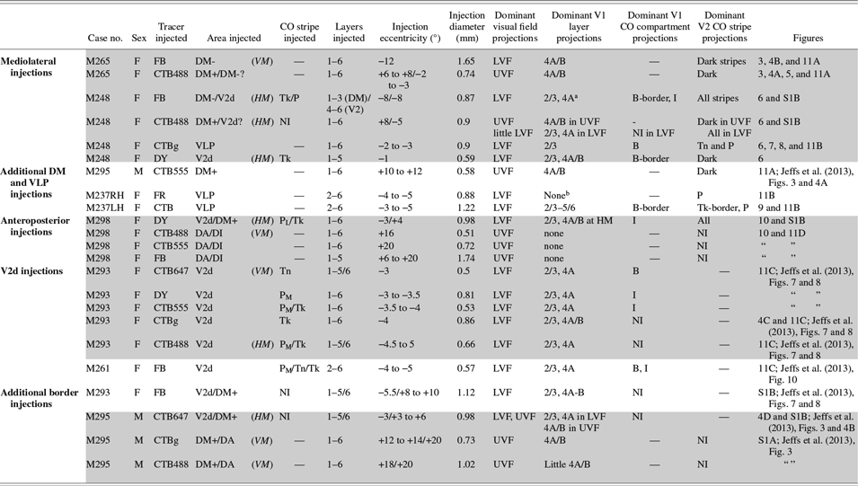

 Open access