

1. Introduction
The North Greenland Icecore Project (NorthGRIP) drilling location (75.10° N, 42.32° W) is situated on an ice ridge where the ice thickness is 3085 m (Reference Dahl-JensenDahl-Jensen and others, 2002). The mean annual temperature is -32°C, and the present annual accumulation in the area averages 19.5 cm ice equivalent. In the upper 80 m of the ice sheet, the firn, the snow gradually compacts to a close packing of ice crystals of typical sizes 1-5 mm. We study crystal-size distributions obtained from 15 vertical thin sections of ice evenly distributed in the depth interval 115-880 m (Reference SvenssonSvensson and others, 2003a). The thin sections have dimensions of 20 cm × 10 cm (height × width) and a thickness of 0.4 ± 0.1 mm. Digital images of ice thin sections placed between crossed linear polarizers are used to map the dimensions of individual ice crystals in the sample (Fig. 1). The ages of the considered samples are all <5300 years (Reference JohnsenJohnsen and others, 2001), and the temperature of the ice in this period can be assumed constant (Reference Dahl-JensenDahl-Jensen and others, 1998).
An image of a 10 × 10 cm2 vertical thin section of ice from 115 m depth. The section is viewed between two crossed linear polarizers, and the different colours represent almost 3000 individual crystals with various orientations of the crystal optical c axes. The inset shows an example of the bounding box used when estimating the crystal size.

Figure 2 shows size distributions of ice crystals at selected depths down to 880 m. The crystal size is defined as the vertical extent of a crystal, which is estimated as the height of the minimal vertically aligned rectangle that encloses the individual crystal (see Fig. 1 inset). Using the horizontally measured sizes of the ice crystals from the thin sections, similar distributions are obtained. The thin sections used in determining the ice size distributions have typical thicknesses of 0.4 ± 0.1 mm, and ice crystals with length scales smaller than this thickness will consequently be either smoothed away when cutting the ice or be invisible in the experimental set-up. These small crystals will be seen as part of the larger crystals and not as individual crystals. This corresponds to an average increase in the sizes of the large crystals, i.e. the lengths we measure x are equal to the real length ![]() plus some noise e of positive mean,
plus some noise e of positive mean, ![]() . We assume that this noise is sufficiently peaked around half the thickness of the thin section, such that we simply put ∊ = 0.2 mm. This value of e can be observed directly as a cut-off in the measured distributions and has been used whenever we compare to theoretical estimates. In addition, we note that ∊ might have a weak x dependence, but we expect it to be negligible compared to the experimental uncertainties.
. We assume that this noise is sufficiently peaked around half the thickness of the thin section, such that we simply put ∊ = 0.2 mm. This value of e can be observed directly as a cut-off in the measured distributions and has been used whenever we compare to theoretical estimates. In addition, we note that ∊ might have a weak x dependence, but we expect it to be negligible compared to the experimental uncertainties.
Distributions of ice crystal sizes at depths115, 165, 220, 330, 440 and 605 m. The crystal size is defined as the maximum vertical extent of the individual crystals. The black lines are the measured histograms, and the smooth grey lines are the temporal evolution predicted by Equation (2) starting directly from the distribution observed at 115 m. Note that already at 165 m depth, only a few of the terms in Equation (6) remain, leading to a smooth shape of the predicted distribution. The total number of ice crystals decreases with depth (due to the overall increase in sizes) until the steady state is reached.

Each distribution exhibits a pronounced peak, indicating a typical crystal size at each depth, followed by an exponentially decaying tail of relatively large crystals. The mean size increases with depth and thus time until it reaches a limiting crystal size, which will vary depending on conditions (Reference Thorsteinsson, Kipfstuhl and MillerThorsteinsson and others, 1997; Reference Li, Jacka and MorganLi and others, 1998). The process behind the grain growth can effectively be described in terms of boundary diffusion between the ice crystals (Reference LouatLouat, 1974). In this respect, it is the grain boundaries rather than the grains themselves that have physical significance. The grains, characterized by small radii of curvature, tend to be eliminated by motions toward their centres of curvature as time passes. This causes smaller crystals to be incorporated into the larger crystals, leading to an overall increase in mean crystal size (Reference Alley, Perepezko and BentleyAlley and others, 1986; Reference PatersonPaterson, 1994). This approximative description leads to the so- called normal grain-growth law that predicts the following temporal dependence of the mean crystal size x:
where x 0 is the initial crystal size and k is the crystal growth rate. This approach was successfully applied for the Greenland Ice core Project (GRIP) ice core by Reference Thorsteinsson, Kipfstuhl and MillerThorsteinsson and others (1997), who fitted their measurements well back to 2500 BP. By definition, however, diffusion does not cause the crystal size to reach a limiting size, whereas the observations clearly indicate a saturation in 〈x 2〈 after 2500 BP (Reference Alley and WoodsAlley and Woods, 1996; Reference GowGow and others, 1997; Reference Thorsteinsson, Kipfstuhl and MillerThorsteinsson and others, 1997).
The important missing part of the physical mechanism in this model is the fact that all crystals, and in particular the large ones, are subjected to fragmentation processes, or what is often referred to in ice physics as polygonization or rotation recrystallization (Reference Alley, Gow and MeeseAlley and others, 1995; Reference Thorsteinsson, Kipfstuhl and MillerThorsteinsson and others, 1997).We include this process in the description here, which then leads to a physical model with a balance between the diffusion of grain boundaries and the fragmentation of crystals, causing the mean crystal size to reach a steady state after 2500 BP.
Another process that has been proposed as important for the production of small crystals is nucleation, or the formation of new grains, which may have c-axis orientations that differ from the dominating vertical orientation of the surrounding crystals. Measurements of the NorthGRIP fabric (c-axis orientations) suggest, however, that nucleation does not play an important role in the Holocene (Reference Wang, Thorsteinsson, Kipfstuhl, Miller, Dahl-Jensen and ShojiWang and others, 2002; Reference SvenssonSvensson and others, 2003a), and therefore nucleation is not included in the model. Models of fabric evolution have also often discussed the process of polygonization and dynamic recrystallization leading to changes in crystal size (see, e.g., Reference ThorsteinssonThorsteinsson, 2002 and references therein).
Recently, we have proposed a simple model for diffusion and fragmentation processes in one dimension (Reference Ferkinghoff-Borg, Jensen, Mathiesen, Olesen and SneppenFerkinghoff-Borg and others, 2003). Here, we elaborate on the physical basis for applying the model to crystal grain growth and further demonstrate the effect of crystal-size saturation and the one-parameter nature of the stationary distribution at large times.
2. The Model
Our proposed model is formulated as a rate equation in the quantity N(x, t), which is the density of ice crystals of length x at time t measured bp. In this study, x is chosen as the vertical extent of the crystals. At a given time, N(x, t) can be increased or decreased by diffusion with a diffusion constant D. It can receive fragments of size x from fragmentations of larger crystals and it can decrease by its own fragmentation. The fragmentation is defined as a rate f in length and time, i.e. for a given time-step dt the average number of fragmentation events over a length L is fL dt.
The fragmentation rate f, and the diffusion constant D, will depend on temperature, non-hydrostatic stresses in the ice and moreover be sensitive to the impurity content of the ice (Reference Alley, Perepezko and BentleyAlley and others, 1986).
These diffusion and fragmentation processes lead to an integral-differential equation of the form

Here, the first term on the righthand side is a diffusion term that corresponds to the grain boundary diffusion of the normal grain-growth law, i.e. if we only include this term in the model we reproduce for large times the parabolic behavior in Equation (1). Note that the equation describes the dynamics of the full assembly of crystals and that the mean square of the crystal sizes therefore follows from

If we only include the diffusion term in Equation (2), we find that for large times 〈x 2〉(t) ~ 4Dt. The behaviour at large times differs from normal diffusion 〈x 2〉 (t) ~ 2Dt by a factor of two because we use the absorbing boundary condition that for all times N(0, t) = 0 (see Reference LouatLouat, 1974, for an explicit solution).This condition expresses the fact that small grains are eliminated and no new crystals will be nucleated.
The second term in Equation (2) is the rate at which crystals of size x fragment, and the last term is the contribution from fragmentation of larger crystals into crystals of size x. Combining the two ways a crystal of size x′ > x can produce a fragment of size x with the assumption that there is a uniform probability, 1/x′, for where the crystal breaks, we obtain

where fx′N (x′) is the number of crystals of size x′ that fragment per time and 2/x′ is the probability for generating a fragment of size x. Note that a uniform probability was already assumed in the definition of the rate f. If we integrate Equation (4) over all crystals larger than x we achieve the last term in Equation (2).
Dividing through by f in Equation (2), we obtain an expression on the righthand side which depends on one parameter a = D/f only. The integral-differential equation has analytic solutions, B[(x + λ)/a 1/3], which are explicitly given in terms of the Bessel function K 1/3 and eigenvalues λ,

The function K
1/3(x) can be written as a sum of the more frequently used Bessel functions 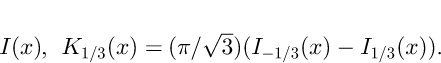 The boundary condition, N(0, t) = 0 for all times t, implies that only a discrete set of non-positive values for λ is allowed. They are found by solving the equation B(λ/a
1/3) = 0. The largest eigen-values are λ0/a
1/3 = 0, λ1/a
1/3 = -2.338..., λ2/a
1/3 = -4.088...,.... The general solution can be written as a linear combination of the eigenfunctions,
The boundary condition, N(0, t) = 0 for all times t, implies that only a discrete set of non-positive values for λ is allowed. They are found by solving the equation B(λ/a
1/3) = 0. The largest eigen-values are λ0/a
1/3 = 0, λ1/a
1/3 = -2.338..., λ2/a
1/3 = -4.088...,.... The general solution can be written as a linear combination of the eigenfunctions,

where the c n’s can be computed from the distribution at time t = t 0 (for further details see Reference Ferkinghoff-Borg, Jensen, Mathiesen, Olesen and SneppenFerkinghoff-Borg and others, 2003). The fact that we have no positive eigenvalues guarantees the existence of a steady-state solution, which is defined by the only surviving term (corresponding to λ0 = 0) for high ages,
The characteristic time, τ, of the exponential growth towards steady state is given by the second largest eigenvalue, λ1, i.e.

When the dynamics has reached steady state, and the mean crystal size has saturated, the distribution is described by the single parameter, a 1/3, which defines the characteristic length scale of the system. In particular, the mean vertical size in the steady state is found to be

In Figure 3 we show the mean vertical size of the ice crystals, 〈x〉(t) as a function of time. The dots are the measured values, and the solid line is an exponential fit corresponding to the two leading terms in the solution,

where 〈x〉0 is the observed average length at time t 0 = 500 years. From the figure, we estimate the characteristic time, τ = 600 ± 70 years and the average length in the steady state 〈x〉∞ = 2.9 ± 0.1 mm. The two parameters correspond to an effective fragmentation rate and a diffusion constant of respectively f = (5.2 ± 0.6) × 10-4 mm-1 a-1 and D = (1.4 ± 0.2) × 10-3 mm2 a-1. Following Equation (3) we obtain the normal grain-growth crystal growth rate k = 4D = (5.5 ± 0.8) × 10-3 mm2 a-1, which corresponds very well to the known values for GRIP, k = 5.6 × 10⁻³ mm2 a-1 (Reference Thorsteinsson, Kipfstuhl and MillerThorsteinsson and others, 1997), and for NorthGRIP, k = 5.8 × 10⁻³ mm2 a-1 (Reference SvenssonSvensson and others, 2003a). We note, however, that the quoted values were obtained from crystal areas and corrected for the sectioning effect with a correction factor of 1.5, whereas the reported value is obtained from the directly measured maximum vertical extent of the crystals within the thin section.
The mean vertical size of the ice crystals shown vs their age in years BP. The smooth line shows the best fit predicfrom our dynamical description of ice crystal growt From the fit we read off the diffusion constant, D ≈ 1.4 × 10⁻³ mm2 a-1, and fragmentation rate, f ≈ 5.2 × 10⁻⁴ a-1 mm-1.

Using these estimates, we can predict the time evolution of crystal sizes from any initial distribution. We assume that possible variations in the initial distributions for each of the samples can be neglected. We therefore directly use the observed distribution at time t 0 = 500 years (115 m depth) as a common initial distribution. The solid lines in Figure 2 show the time evolution of this distribution, in good agreement with the measurements.
When comparing the model to the vertical crystal sizes, we should in principle take into account the vertical compression of crystals due to the ice flow. Had we chosen the horizontal crystal sizes for comparison, we should have taken into account the corresponding elongation. However, observations show that the crystal flattening, which is defined as crystal width divided by crystal height, is <15% for the applied samples (Reference SvenssonSvensson and others, 2003b), so in order to keep things reasonably simple, we ignore this effect.
3. Discussion and Conclusions
During an annual cycle, the impurity content and the average crystal size show important variations with the highest dust load and the smallest crystals appearing during spring (Reference SvenssonSvensson and others, 2003b). Because the size of the applied samples (20 cm depth) is close to the annual accumulation at NorthGRIP (19.5 cm ice equivalent), the seasonal variability will, to first order, be averaged out in the experimental data. Still, some interannual variations in the impurity content of the ice are observed (Reference SvenssonSvensson and others, 2003b). These fluctuations may explain the small discrepancies between model and observations in Figures 2 and 3, since the values of D and f are determined by the average concentration. We can take these fluctuations into account for the older samples, which have almost reached a steady state, by rescaling the crystal-size distributions. In Figure 4 we demonstrate that this rescaling results in a universal curve for all the size distributions, described by the steady-state Bessel function solution, which is significantly different from the widely used log-normal distribution. The “data collapse” in the figure, i.e. the fact that all the rescaled distributions have the same shape, clearly supports the one- parameter nature of the steady-state solution Equation (7).
The figure shows a “data collapse” of the size distributions as a consequence of a rescaling, ![]() i.e. the distributions shown have zero mean and unit standard deviation. The lines correspond to the distribution used in the eight data points in Figure 3 of the oldest samples (t >2500 years).The black line on top is the steady-state solution of Equation (2).We use the rescaling
i.e. the distributions shown have zero mean and unit standard deviation. The lines correspond to the distribution used in the eight data points in Figure 3 of the oldest samples (t >2500 years).The black line on top is the steady-state solution of Equation (2).We use the rescaling ![]() in order to improve the resolution around the smallest crystal sizes and note that the steady-state solution is transformed accordingly.
in order to improve the resolution around the smallest crystal sizes and note that the steady-state solution is transformed accordingly.

By formulating Equation (2) we thus provide a comprehensive description of the dynamical processes of ice crystals. Our model improves the normal grain-growth law based on diffusive growth alone and offers an explanation of the reach of a steady state for the mean crystal size by means of fundamental physical processes. The good agreement between data and model suggests that polygonization/fragmentation is the dominant process in the production of small crystals, rather than nucleation of new crystals, a process not included in the model. The suggested interplay between the diffusion and the fragmentation in the crystal grain growth is believed to be an essential ingredient of many other systems in nature (e.g. geological and perhaps biological processes; see Reference Ferkinghoff-Borg, Jensen, Mathiesen, Olesen and SneppenFerkinghoff-Borg and others, 2003) and could be a useful tool to predict the distribution curves of fragmented pieces.


