


Impact statement
This work presents a reusable, mass-manufacturable microdroplet generation platform designed to reduce material waste and extend device lifetime through circular design principles. By separating durable housing components from replaceable microchannel layers, the system enables rapid cleaning, component-level replacement, and recovery after fouling events, rather than requiring disposal of entire devices. Throughput is increased by stacking multiple channel networks within a single reusable housing, improving material efficiency per unit output. Together, these features illustrate how material selection, manufacturing strategy, and modular design can support scalable, resource-efficient microfluidic technologies, with relevance to reducing waste in laboratory-scale manufacturing and advancing more sustainable experimental and translational workflows.
1. Introduction
Microfluidic technologies enable precise manipulation of fluids at the microscale [Reference Shah, Shrivastav, Ghate and Chavda1], but this precision is often achieved at the expense of device longevity and material efficiency. Many microfluidic systems rely on micron-scale channels that are difficult to clean and prone to fouling, leading to frequent discarding after short periods of use, particularly when small or complex channels are used, and performance is prioritized over reuse [Reference Lepowsky, Amin and Tasoglu2, Reference Shields, Ohiri, Szott and López3]. As a result, device architectures are commonly optimized for single-use operation rather than for extended lifetime, recoverability, or component-level reuse. As microfluidic methods continue to expand across research and applied settings such as precision medicine, the cumulative material waste associated with short-lived or disposable devices has become an increasingly important consideration. In addition, the lack of design strategies that explicitly address reuse, cleaning, and redeployment represents a fundamental barrier to translating microfluidic technologies into sustainable, scalable platforms.
Emulsion-based microfluidics are designed to make precise emulsions through immiscible flows and allow for the controlled generation of individual emulsions [Reference Teh, Lin, Hung, Lee and Microfluidics4, Reference Han and Chen5], commonly either oil-in-water or water-in-oil. Such emulsions have been widely used in various fields, including cosmetics [Reference Le Révérend, Taylor and Norton6], pharmaceuticals [Reference Tamilvanan and Benita7], food production[Reference Degner, Chung, Schlegel, Hutkins and McClements8], and biological and chemical research [Reference Liu, Deroy and Herr9, Reference Liu, Yang, Du and Pang10, Reference Ding, Howes and deMello11]. One common application is the encapsulation of microbes within individual droplets, which enables detailed investigation of microbial interactions with their microenvironments, including nutrient uptake, metabolite secretion, and motility [Reference Liu, Deroy and Herr9]. Achieving this level of control typically requires small channel dimensions, which can further exacerbate fouling, clogging, and short operational lifetimes.
Microdroplet generators can be fabricated in a variety of ways, from soft lithography using silicone polymers and masters fabricated in cleanrooms to the forming of concentric glass capillaries. While many fabrication methods are both accessible and widely used, they can be limited by long fabrication times [Reference Felton, Hughes and Diaz-Gaxiola12] and relatively high costs of both materials and/or fabrication facilities [Reference Nguyen, Thach, Roy, Huynh and Perrault13, Reference Niculescu, Chircov, Bîrcă and Grumezescu14]. In addition to these practical constraints, many microfluidic devices are designed for single or limited use, which can restrict scalability and contribute to material waste when devices are discarded after fouling or failure. As a result, there has been growing interest in the development of reusable microdroplet generator systems to improve accessibility and reduce reliance on repeated fabrication [Reference Lepowsky, Amin and Tasoglu2, Reference Lepowsky and Tasoglu15]. While some excellent approaches to reusable microfluidic devices have been proposed [Reference Samandari, Rafiee, Alipanah, Sanati-Nezhad and Javanmard16, Reference Mazio, Scognamiglio and Passariello17, Reference Li, Zhao, Liu, Xu and Wang18, Reference Park, Ryu and Han19], there remains a need for low-cost, mass-manufactured systems that combine reusability with rapid disassembly and reassembly.
An additional advantage of microdroplet generator systems that can be readily disassembled is their suitability for high-fouling applications, in which one or more fluid phases may accumulate or solidify within microchannels. In microdroplet generation, the high surface area-to-volume ratio of the fluid in micron-scale channels can lead to rapid accumulation of solid components, potentially resulting in clogging and degraded performance[Reference Bakhtiari and Kähler20]..Cleaning such channels is often challenging without full device disassembly [Reference Lepowsky, Amin and Tasoglu2], and as a result, aggregates, coagulants, or biofoulants can significantly shorten device lifetimes and compromise measurement accuracy [Reference Lepowsky, Amin and Tasoglu2, Reference Shields, Ohiri, Szott and López3]. Certain dispersed phases used in microdroplet generation, including polymeric or gelling materials, are particularly prone to fouling and channel blockage [Reference Desbois, Padirac and Kaneda21], making their use more resource-intensive and inhibiting application in continuous systems [Reference Kang, Kim and Kim22]. Systems that support effective cleaning and reuse, therefore, offer an opportunity to reduce premature device disposal while enabling experimentation with challenging materials that would otherwise limit operational longevity.
In this work, we present a scalable, cost-effective microdroplet generation platform that integrates mass-manufactured microchannel networks into a reusable, modular housing to extend device lifetime and reduce material waste. The microchannels are fabricated via roll-to-roll processing with dimensions down to 50 μm, while the housing separates durable structural components from replaceable channel layers. Devices are assembled from polycarbonate and silicone layers using mechanical compression, enabling reliable sealing without permanent bonding and allowing rapid disassembly, cleaning, and reuse. The modular design also supports vertical stacking of multiple channel networks to increase throughput without expanding system footprint. Performance is evaluated using a high-fouling hydrogel dispersed phase under temperature-induced gelation conditions, demonstrating that fouled channels can be effectively cleared and reused. Overall, this platform supports high-throughput droplet generation while aligning with circular design principles through modularity, reuse, and component-level replacement. Furthermore, the development of reusable and mass-manufacturable microfluidic systems aligns with United Nations Sustainable Development Goals, including SDG 9 (Industry, Innovation and Infrastructure) [23] through scalable manufacturing approaches and SDG 12 (Responsible Consumption and Production) [24] by reducing reliance on single-use laboratory devices.
2. Experimental Section
2.1. Microdroplet Generator Design and Fabrication
The droplet generator was engineered as a flow-focusing device [Reference Chen, Kuo and Liu25, Reference Gupta, Matharoo, Makkar and Kumar26] with microfluidic channels measuring 50 μm in width and 30 μm in height. A computer-aided generator design was created using SolidWorks (2021) and submitted to Sappi North America to fabricate a metal master. The casts were produced via roll-to-roll manufacturing [27], yielding a 50-pound roll of cast textures.
2.2. Housing Fabrication and Device Assembly
The housing design was created using Trotec Ruby software, and the silicone and polycarbonate layers were laser cut (Speedy 400, Trotec Laser, Marchtrenk, Austria). Importantly, a ~200 μm well was laser cut into the top silicone layer just above the outlet channel to allow the droplets to spread out and assume a spherical shape directly after formation. The silicone tubing for the continuous phase (oil) was inserted directly into the polycarbonate layer and sealed with clear silicone caulk. A 90-degree metal elbow was epoxied into the outlet and dispersed phase (water) inlet.
Each device component was individually cleaned before use. Polycarbonate layers were sprayed with 70% ethanol and wiped with a KimTech microfiber cloth (Kimberly Clark, Hendersonville, NC). The silicone rubber layer was sprayed with 70% ethanol, rinsed with water, and dried with compressed air. The microdroplet generator pattern was sonicated for 2 min in isopropyl alcohol and dried with compressed air. The silicone layer was positioned inside the top polycarbonate layer, and the microdroplet generator pattern was aligned with the inlets [Reference Shuler and Sung28, Reference Lai, Yang, Wu and Li29, Reference Pérez-Sosa, Peñaherrera-Pazmiño and Rosero30]. The components were assembled and tightened by hand to ensure an even seal at minimal pressure. The syringes were connected via silicone tubing and placed in syringe pumps (Fisher Scientific, Waltham, MA).
2.3. Measurement of Droplet Size
The microdroplet generator housing was assembled as already described. Mineral oil with 5% Span 80 was used as the continuous phase with a flow of 50 μL h−1, and it ran for 1 h, to ensure a steady flow rate through the channels. Droplets were visualized using an EVOS Auto Flo microscope (Carlsbad, CA), and an image of the droplets within the outlet channel was imaged. The droplet diameters were measured using Fiji ImageJ (version 1.53t). The volume was calculated from the measured radius r, assuming spherical droplets. A comparison of the droplet volume calculated from collected droplets and droplets within the channel was performed (Supplementary Fig. S1).
For single-use droplet generators, the dispersed phase flow rate was chosen randomly between 10–50 μL h−1 in 10 μL h−1 increments. The dispersed phase flow rate was adjusted and run for approximately 5 min, with images taken after each change. This process was repeated until all flow rates were tested.
For reuse droplet generators, the dispersed phase flow rate was set to 30 μL h−1, and a continuous phase flow rate of 10 μL h−1. The generator ran for 1 h to allow for stabilization, then an image of the droplets was captured. The device was disassembled and cleaned. A new set of silicone and channels was then inserted into the housing for the subsequent run, while the original set was left to rest for 24 h to allow for the silicone layer to return to its original shape. Without the critical resting period of 24 h, the silicone layer sags into the channels due to the impact of cyclic loading on the silicone mechanical properties. This process was repeated for a total of five runs.
2.4. Multiplexing Assembly
Two-microdroplet generators were prepared for stacking by cutting the inlet and outlet ports with the laser cutter. The laser-cut generators and one normal generator were cleaned, as already described. The housing unit was modified to have two extra sheets of silicone. The generators were assembled in the housing unit with silicone sheets separating each of the droplet generators. Due to the need for increased stiffness, Shore 60A silicone was used instead of the normal 50A silicone. The inlet continuous phase was set to 50 μL h−1, and the dispersed phase was set to 40 μL h−1.
2.5. Assembly of the Agar Trial
The agar was prepared with a concentration of 4% w/v in deionized water. The agar was heated until all powder was dissolved. The agar dispersed phase was set to 20 μL h−1 and the mineral oil continuous phase was set to 50 μL h−1. A heating system was implemented to control the temperature of the agar as it entered the system. The heating system consisted of copper tubing coils around a reservoir of agar (~1 mL) at the dispersed phase inlet and embedded in the polycarbonate layer. A thermistor was placed in the agar reservoir to monitor the temperature using a digital multimeter. A peristaltic pump was used to deliver 60°C water from a beaker on a hot plate through the copper tubing. With steadily flowing agar and microdroplets being generated, the beaker of heated water was removed from the hot plate and subsequently placed in an ice bath to cool. The generators were cleaned and assembled.
2.6. Statistical Analysis
All statistical analyses were performed using JMP. Statistical analyses were performed to compare droplet volume between reuse cycles to confirm that there are no statistical differences. Statistical analysis was also used to confirm no statistical differences between droplet volume measurement methods. Data normality was assessed using the Shapiro–Wilk test. For comparisons among groups, a one-way ANOVA followed by Tukey’s post hoc test was used to identify statistically significant differences (p < 0.05).
3. Results and Discussion
3.1. Overview of the Microfluidic Device and Assembly
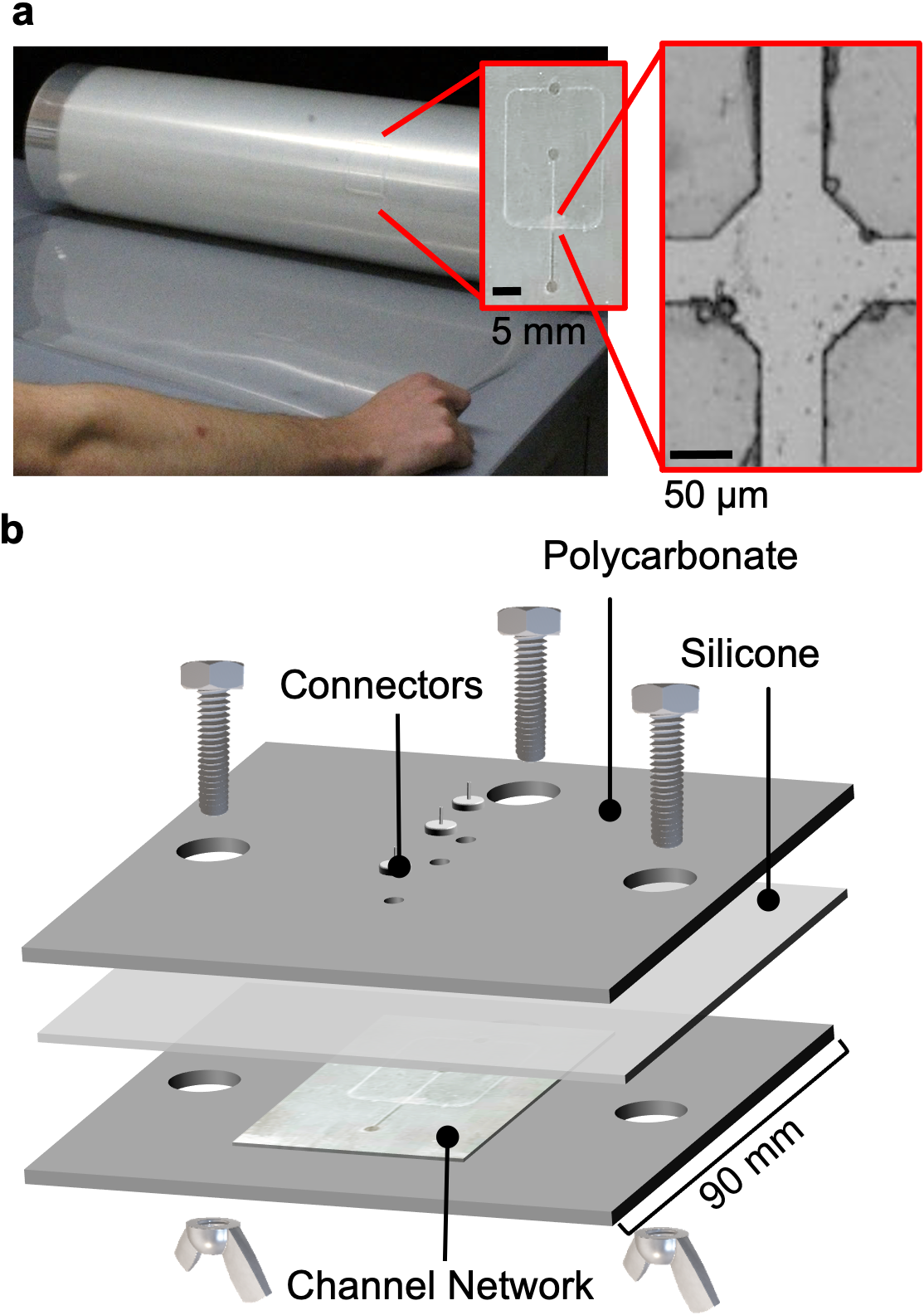
Since the manufacturing of channels ≤50 μm typically requires a cleanroom with time-extensive processes [Reference Niculescu, Chircov, Bîrcă and Grumezescu14], which can result in resource-intensive fabrication and limited scalability, we aimed to design, fabricate, and evaluate a microdroplet generator with 50 μm-wide channels. Due to Sappi’s ability to fabricate cast materials at large scales, their textures have been previously used for microfluidic devices [Reference Boutiette, Toothaker, Corless, Boukaftane and Howell31] and, more recently, for sensors [Reference White, Miner and McKinney32, Reference White, Miner and Craig33]. A flow focusing channel design was reproduced from previous research by Tan et al. [Reference Tan, Cristini and Lee34], in a computer-aided design file and sent to Sappi for fabrication. The resulting 100 m roll, consisting of the individual microdroplet generator channel networks, is shown in Fig. 1a. Fig. 1a also includes insets showing an individual droplet generator and a magnified view of the droplet formation junction. The junction is depicted under empty-channel conditions, with no aqueous phase introduced. The apparent bubbles observed along the channel walls are not droplets but rather minor surface imperfections arising from the fabrication process. As Sappi produces 4,200 m2 of cast material per hour [Reference Boutiette, Toothaker, Corless, Boukaftane and Howell31], this translates into the potential to create up to 5.9 million individual microdroplet generator channel networks per hour. Additionally, the use of mass-manufactured paper coating techniques for microchannel fabrication, in place of cleanroom-based processes, substantially reduces material waste generated during device fabrication.
Overview of the microdroplet generator system. (a) Photograph of the mass-manufactured roll containing microdroplet generator casts. Insets: the entire cast channel network and a close-up of the junction without aqueous fluids. (b) Exploded view of the housing unit needed to generate microdroplets containing the polycarbonate sheets, silicone sheet, microdroplet generator, wingnuts, and bolts.

Figure 1. Long description
The top panel is a photograph of a cylindrical roll containing mass-manufactured microdroplet generator casts, positioned horizontally with a person's arm for scale. Two red insets zoom in: the first shows the entire cast channel network with a black scale bar labeled 5 mm, and the second provides a close-up of a junction in the channel network without aqueous fluids, with a black scale bar labeled 50 micrometers. The bottom panel is an exploded technical diagram of the microdroplet generator housing unit, arranged vertically from top to bottom. The topmost layer is labeled polycarbonate, followed by a silicone sheet, then another polycarbonate layer. Between these layers is the microdroplet generator with the channel network visible. Four bolts and wingnuts are shown as connectors, with arrows indicating assembly through the aligned holes. The channel network is labeled, and the width of the assembly is marked as 90 millimeters. The diagram clarifies the spatial relationship and assembly order of each component.
A comparison of the present system with previously reported droplet generation platforms, including fabrication methods, scalability, and reusability, is provided in Supplementary Table S1. The table also highlights techno-economic considerations associated with different fabrication approaches. Conventional microfluidic systems often rely on specialized infrastructure and are designed for limited reuse, increasing material consumption per experiment. In contrast, the reusable housing and roll-to-roll fabricated channel layers presented here allow fabrication and material inputs to be amortized across multiple uses. While a full techno-economic analysis is beyond the scope of this work, these features suggest reduced cost per use and improved material efficiency relative to single-use platforms.
The system was designed such that the oil continuous phase was introduced through the uppermost inlet port, flowing horizontally into the cross-junction. Simultaneously, the water dispersed phase enters through a secondary inlet port, flowing downward toward the junction. Importantly, to promote droplet stabilization, a surfactant (Span 80) was incorporated into the continuous oil phase. No surfactant was added to the dispersed aqueous phase to preserve its intended composition and prevent alterations in droplet formulation. Since the channel systems produced by Sappi are open on one side, the top of the channels must be sealed to prevent fluid leakage and ensure fluid containment. Rather than using permanent bonding, which would prevent reuse, sealing is achieved using a mechanically compressed housing that allows the channel networks to be removed, cleaned, and reused, as shown in Fig. 1b. The housing comprises two polycarbonate sheets, each 6 mm thick, epoxied with metal tubing to allow for tubing connection. Importantly, while the epoxy allows the metal tubing to connect to the pump tubing without leaking, its use will limit end-of-life recycling of the housing. The housing also comprises a 1.6 mm silicone sheet with a Shore hardness of 50A. The 50A hardness of the silicone layer was chosen because it caused less leakage than 60A silicone, likely because its softer nature allowed it to deform around small defects in the cast channels and around any dust or other particulates. Furthermore, polycarbonate was chosen due to its durability and resistance to temperature fluctuations [Reference Federation35]. The housing is secured using bolts and wingnuts along the top sides of the polycarbonate sheet. A silicone layer is placed between the top polycarbonate sheet and the droplet generator to ensure proper channel sealing despite slight surface imperfections or roughness in the generators or polycarbonate sheets. Since the pressure inside the microfluidic channels is high [Reference Cheri, Shahraki, Sadeghi, Moghaddam and Latifi36], robust housing materials are required to withstand the pressure exerted (~100–160 kPa) [Reference Shen, Ai, Ma, Li and Xue37] and prevent leakage. By decoupling the durable housing from the replaceable channel networks, the system allows fouled or damaged channel layers to be exchanged without discarding the entire device, supporting component-level replacement rather than single-use disposal. Notably, while the current assembly process involves manual alignment and fastening steps for prototype validation, the roll-to-roll fabrication of the microchannel layers demonstrates the scalability of the core device architecture, and future iterations could incorporate automated alignment and bonding to further support scalable and resource-efficient manufacturing workflows.
Importantly, the underlying fluid dynamics of the microfluidic device must be carefully considered, and the corresponding droplet formation regime well understood, for the successful design and operation of the proposed multifluidic systems. Specifically, the dispersed phase flow rate was varied from 10 to 50 μL h−1, while the continuous phase was fixed at 50 μL h−1. The interfacial tension between water and mineral oil in the presence of Span 80 was previously quantified using the drop shape analysis method and reported to be approximately 5 mN m−1 [Reference Bashir, Solvas, Bashir, Rees and Zimmerman38]. The viscosity of the mineral oil is between 0.05 and 0.07 Pa s [39]. therefore, the capillary number was calculated to be 0.1, resulting in the droplet formation regime of the device being dripping [Reference Mardani, Falahatian and Taghipoor40, Reference Yeom and Lee41]. The presence of a dripping regime in this system, in which the dispersed phase is pinched off by the continuous phase, leading to the breakup of the dispersed phase into individual droplets that moves toward the outlet [Reference Fu, Wu, Ma and Li42], is further supported by droplet formation images, as shown in Supplementary Fig. S2. Importantly, in dripping regimes, the droplet size created is controlled by the channel size, interfacial tension, and the phase fluid viscosities and flow rates [Reference Hua, Zhang and Lou43].
3.2. Characteristics of Droplets Generated
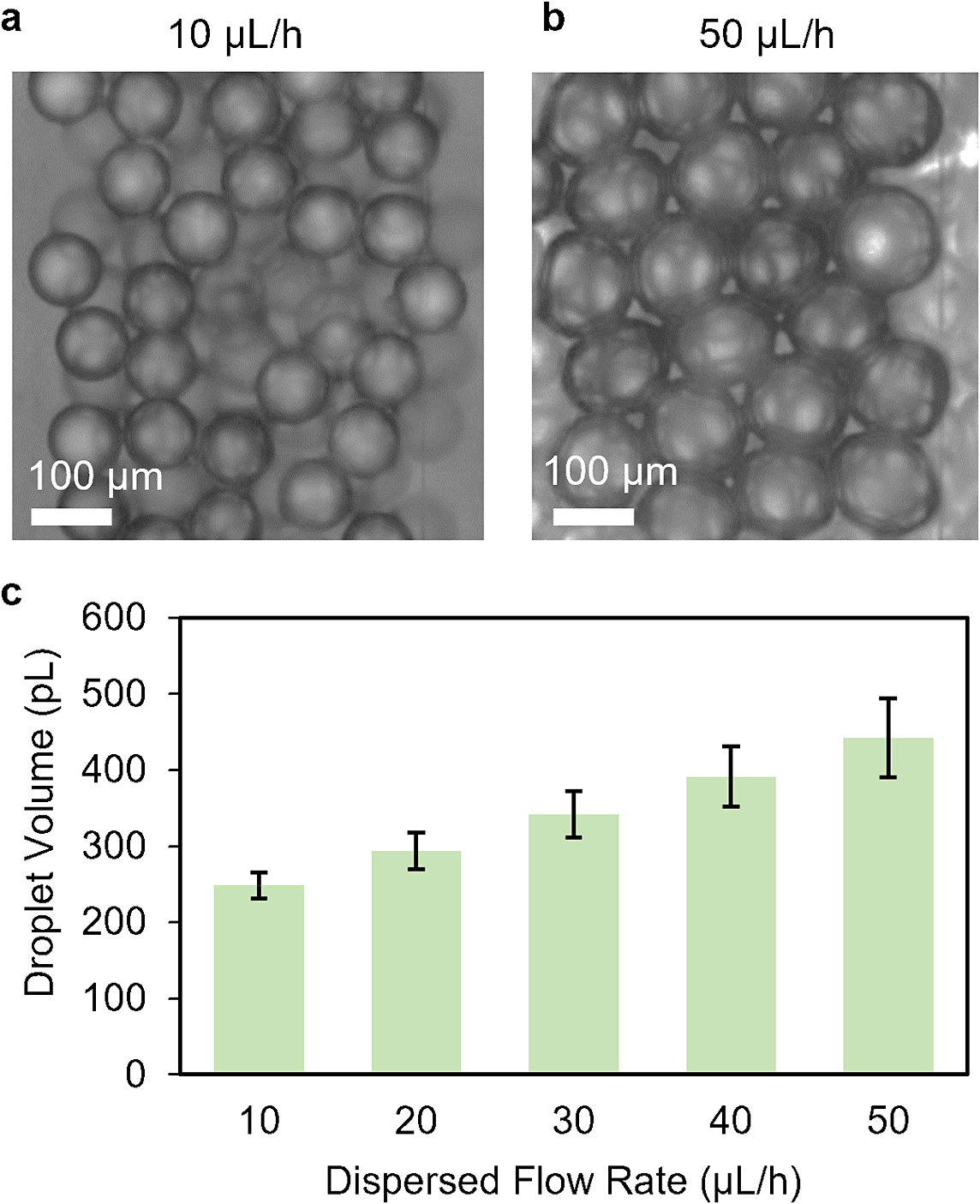
The size and uniformity of the droplet were characterized at changing dispersed phase flow rates of 10–50 μL h−1 to understand the influence of the dispersed phase flow rate on droplet volume in this system. Importantly, the continuous phase must wet the channel walls effectively to facilitate droplet formation in a flow-focusing system [Reference Trantidou, Elani, Parsons and Ces44]. The cast devices have been measured to exhibit a water contact angle of 98° ± 3°, indicating their hydrophobic nature. Due to the hydrophobicity of the cast devices and the top silicone layer [Reference Owen45], water-in-oil emulsions can be generated without the need for surface treatments, thereby avoiding additional chemical modification steps that could complicate reuse or limit device lifetime. Images of the droplets within the channels at dispersed phase flow rates of 10 μL h−1 and 50 μL h−1 are shown in Fig. 2a. As the silicone layer above the outlet channel had been cut to provide a deeper well for collection, the droplets adopted a spherical shape within it, enabling direct volume measurements without the need for external collection. However, to ensure measurements of the droplet volumes within the channels were accurate, the droplet sizes were measured both in the outlet channel and after external collection (Supplementary Fig. S1); the results showed no statistical difference in volumes between the two. Since droplet characterization can be performed in situ, it reduces handling steps and minimizes consumable use associated with collection. Droplet volumes increased linearly with the dispersed-phase flow rate, consistent with Eq. (2), as shown in Fig. 2b. For example, the dispersed flow rate of 10 μL h−1 produced 248 pL ± 17 pL droplets, while the 50 μL h−1 flow rate produced 442 pL ± 52 pL droplets. Therefore, we performed a linear fit of the droplet volume versus dispersed-phase flow rate to Eq. (2) in the Supplementary Material, obtaining the droplet generation frequency f = 57.3 Hz. This value was then compared with the measured experimental frequency, showing good agreement. The calculated coefficient of variance for the droplet volume as a function of dispersed-phase flow rate is shown in Supplementary Fig. S3. Furthermore, five different cast droplet generators were used in the experiment, demonstrating low variability between different cast microfluidic devices.
Droplet formation in the microdroplet generators at different dispersed flow rates. (a) Images of the water droplets once entering the wider channel of the microdroplet generators with the dispersed phase flow rates of 10 μL h−1 and (b) 50 μL h−1. (c) Graph of the droplet volumes for the dispersed flow rates between 10–50 μL h−1 (n = 5).

Figure 2. Long description
The top row contains two grayscale micrographs. Panel a, at the top left, shows water droplets in a wider microchannel at a dispersed phase flow rate of 10 micro liters per hour. Droplets appear smaller and more closely packed. Panel b, at the top right, shows droplets at 50 micro liters per hour, which are visibly larger and more densely arranged. Both panels include a scale bar labeled 100 micro meters. The bottom panel, labeled c, is a bar graph with the x axis labeled Dispersed Flow Rate in micro liters per hour, ranging from 10 to 50 in increments of 10. The y axis is labeled Droplet Volume in pico liters, ranging from 0 to 600. Five green bars represent droplet volumes at each flow rate: approximately 230, 290, 340, 390, and 450 pico liters, each with an error bar. The graph shows a positive trend, with droplet volume increasing as dispersed flow rate increases.
3.3. Housing Enables Reusability
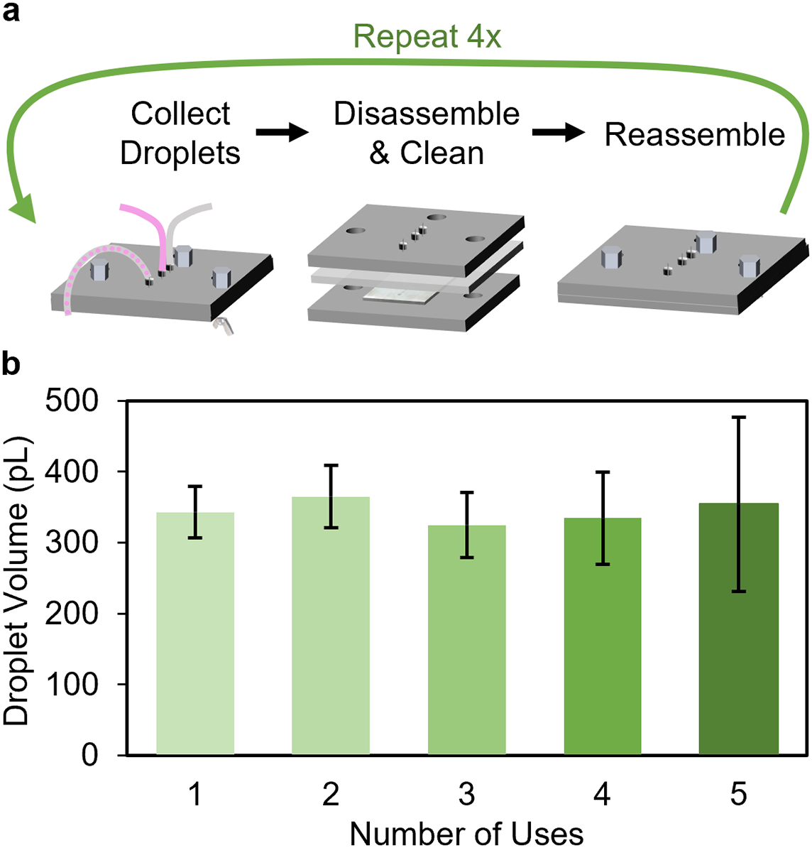
Due to the small channel dimensions (~50 μm) of the microdroplet generators, blockages can occur when aggregates or particulates are present in the dispersed phase, or when one phase begins to change from liquid to a gel. In many conventional microfluidic systems, such fouling events lead to premature device disposal, contributing to material waste and limiting operational lifetime. Therefore, the ability to disassemble, clean, and reuse the droplet generators easily would potentially facilitate the use of clog-prone phases such as polymers or gels [Reference Samandari, Rafiee, Alipanah, Sanati-Nezhad and Javanmard16, Reference Mazio, Scognamiglio and Passariello17, Reference Li, Zhao, Liu, Xu and Wang18], while supporting extended device lifetimes through reuse rather than replacement. Fig. 3 shows the reusability of the droplet generators. A schematic of the reusability process is shown in Fig. 3a. The housing and generator are assembled and used until a blockage occurs, at which point the system can be disassembled, cleaned, and reassembled, restoring functionality without the need to discard the housing or channel network. Disassembly took approximately one minute, cleaning the silicone and polycarbonate took ~4 minutes, and sonicating the microdroplet generator took ~2 minutes. Reassembly of the device took ~5 minutes, and the entire process averaged 12.5 minutes, highlighting the rapid device turnaround for repeated experiments and enabling efficient reuse in iterative or high-throughput workflows. Notably, the silicone layer of the housing requires approximately 24 hours to fully recover its elasticity, which can limit the speed of reuse. However, implementing a strategy of interchangeable silicone layers would allow one layer to rest while another is in use. Through this method, the silicone layer would be switched out after every reuse and stored for at least 24 hours, while the housing, tubing, pumps, and microdroplet generator can be retained, significantly improving overall turnaround time and further extending the practical reusability of the system without increasing material consumption of the housing components. Fig. 3b shows the droplet volumes over the five uses of the same microdroplet generators. Importantly, there were no significant differences between the reuse cycles (Supplementary Fig. S4). There was a slight increase in the standard deviation of the droplet volume over sequential uses, which may be due to slight deformations in the silicone sheet over repeated compressional stress on the layer during droplet generation [Reference Song, Cho, Park and Kim46]. Channel widths remained consistent across reuse cycles (Supplementary Fig. S5), confirming that the increased standard deviation in droplet volume is likely caused by the silicone layer and not changes in the channel system itself. While the device was only tested for five cycles, this was intended solely as a demonstration and does not represent a limitation. Based on repeated use during device development and experimental testing, the microdroplet generator channel networks were observed to remain functional for at least 50 uses, while the mechanically compressed housing components (excluding silicone elements) were reused for well over 100 experimental runs. These estimates are derived from cumulative usage across preliminary and reported experiments rather than from a dedicated lifetime study; systematic long-term durability testing is ongoing. With appropriate handling and cleaning, the system may therefore support additional reuse cycles beyond those demonstrated here, further reducing the need for repeated fabrication and supporting circular use of microfluidic components.
Reusability of the droplet generators. (a) Process for reusing the droplet generators with the collection of droplets, disassembling and cleaning, and reassembling the device for more droplet collection. (b) Droplet volume from the dispersed phase of 30 μL h−1 across five different uses of the same droplet generator (n = 5).

Figure 3. Long description
The top panel contains three schematic steps arranged left to right. The first step, labeled Collect Droplets, shows a device with three colored tubes. The second step, Disassemble and Clean, shows the device separated into layers. The third step, Reassemble, shows the device reassembled. A green arrow labeled Repeat 4x curves from the right end back to the left, indicating the process is repeated four times. The bottom panel is a bar graph with x-axis labeled Number of Uses from 1 to 5 and y-axis labeled Droplet Volume in p L from 0 to 500. Five vertical bars, each with an error bar, show droplet volumes for each use: all bars are between approximately 320 and 370 p L, with overlapping error bars, indicating consistent droplet volume across uses.
3.4. Generators Can Be Stacked to Enable Multiplexing
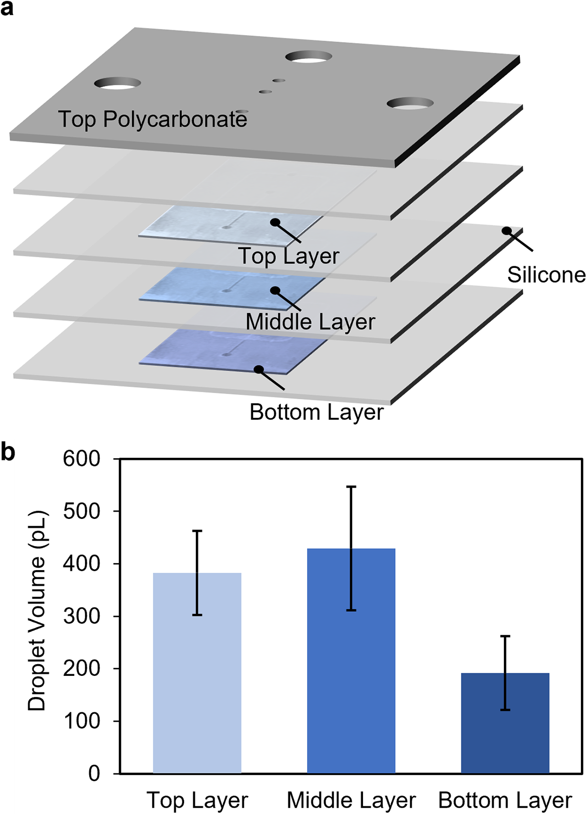
To overcome the limitation in droplet throughput associated with individual microdroplet generators [Reference Wei, Sun, Ren and Li47], multiple generators were stacked on top of each other. Specifically, three microdroplet generators were aligned and stacked in parallel to achieve higher droplet production without increasing the system footprint or requiring additional fluidic inlets and outlets, thereby increasing output per unit device material. The inlet and outlet ports of the upper two generators were laser-cut to enable fluid flow through the stacked layers. A silicone sheet was added between each layer to ensure proper sealing and alignment, as shown in Fig. 4a, with the distribution of droplet volumes produced across the three layers is shown in Fig. 4b. A video of the three layers of the microdroplet generators running simultaneously is shown in Supplementary Video S1. The droplet production rates for the three layers were broadly similar, though some variability was observed. The top, middle, and bottom layers produced 51,600 ± 7,493 droplets/h, 58,800 ± 5,499 droplets/h, and 52,800 ± 10,998 droplets/h, respectively. The variability in droplet size is likely due to pressure variations caused by slight deformation of the silicone layer rather than differences in production rate. As the silicone sags into the microfluidic channels, it locally reduces the channel height, leading to a pressure increase, particularly in the bottom layer. This increased pressure likely reduces the flow rate, resulting in smaller droplet sizes. Despite inter-layer variability in droplet volume (~200–400 pL), the system demonstrates strong potential for scalable droplet generation, while maintaining a reusable housing and modular architecture. The droplet uniformity could potentially be improved by optimizing flow rates and using feedback loops [Reference Miller, Rotea and Rothstein48, Reference Crawford, Smith and Whyte49]. Furthermore, there is also a potential to increase the number of generators stacked beyond just three; however, further development of such a system would require considering how to visualize droplet production as each stack adds ~1.65 mm of depth, which when combined with the thickness of the housing quickly goes beyond the standard working distance of most microscopes. Notably, while the current throughput is modest relative to industrial-scale emulsification systems, the primary objective of this work was to demonstrate the scalability and reusability of a mass-manufacturable droplet generation platform rather than to maximize production rate. By enabling increased throughput through stacking rather than duplicating complete devices, this approach supports more material-efficient scaling strategies. Future iterations could markedly increase throughput by integrating additional stacked layers or parallelized channel arrays, as well as by optimizing flow distribution and implementing automated assembly processes, further enhancing performance without proportionally increasing material consumption.
Multiplexing of the droplet generators. (a) Exploded view of the multiplexed microdroplet generators with the top (light blue), middle (blue), and bottom (dark blue) microdroplet generators separated by a silicone sheet. (b) Volumes of the droplets created in the three generator channels after ~1 h of running with a dispersed phase at 40 μL h−1 (n = 3).

Figure 4. Long description
The top left panel is an exploded schematic showing five stacked layers from top to bottom: Top Polycarbonate, Top Layer, Middle Layer, Bottom Layer, with silicone sheets separating the microdroplet generator layers. Each microdroplet generator layer is labeled and color-coded: Top Layer in light blue, Middle Layer in blue, Bottom Layer in dark blue. The top polycarbonate layer has three large and two small circular holes. The right panel is a vertical bar graph with the y-axis labeled Droplet Volume (picoLiters) from 0 to 600 and the x-axis labeled with Top Layer, Middle Layer, and Bottom Layer. The Top Layer bar is light blue and reaches about 380 picoLiters, the Middle Layer bar is blue and reaches about 430 picoLiters, and the Bottom Layer bar is dark blue and reaches about 180 picoLiters. All bars have error bars indicating standard deviation.
3.5. System Use for Hydrogels
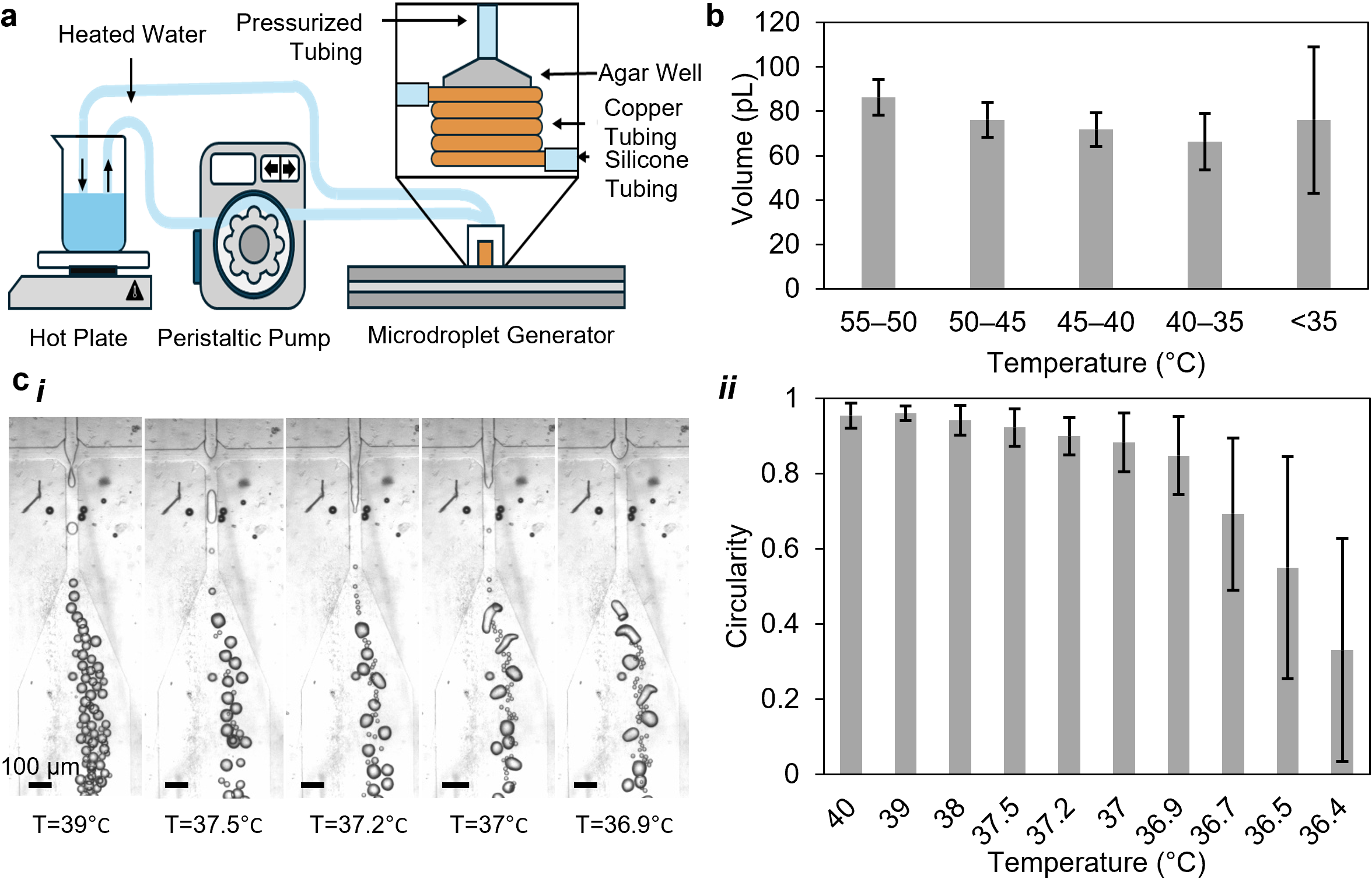
Hydrogels, polymeric materials of significant chemical engineering interest due to their versatility in applications, such as drug delivery, sensing, and actuation [Reference Wei, Sun, Ren and Li47], are notably prone to fouling when employed in microdroplet generation systems. In many conventional microfluidic platforms, such fouling can permanently compromise device function, leading to disposal after a single use. Given the utility of hydrogels, we evaluated the performance of the microdroplet generators using agar in the dispersed phase to create agar emulsion, a common hydrogel that gels around 40°C [Reference Aymard, Martin and Plucknett50]. This gelation temperature corresponds closely to the well-documented sol–gel transition of agar systems, where a sharp rheological transition occurs over a narrow temperature window (~40–35°C), characterized by rapid increases in viscoelastic properties due to helix formation and network aggregation [Reference Aymard, Martin and Plucknett50]. To allow for temperature control, copper tubing was added to the inlet and kept filled with heated water via a peristaltic pump ( Fig. 5a ). Measurements of the droplet volume as the temperature was lowered from 55°C to 35°C showed a sharp decrease combined with an increase in variability ( Fig. 5b ), likely caused by the increase of agar viscosity with decreasing temperature [Reference Ghebremedhin, Seiffert and Vilgis51]. Previous rheological studies show that below approximately 35°C, agar undergoes rapid gelation with a sharp increase in elastic modulus and associated apparent viscosity, whereas above this temperature, gelation is significantly slower and the system remains weakly structured [Reference Aymard, Martin and Plucknett50]. Consequently, the velocity of the liquid agar entering the system is inhibited. A decrease in the flow rate of the dispersed phase results directly in a decrease in droplet size [Reference Zhu and Wang52]. This strong temperature dependence of rheology implies a highly nonlinear viscosity–temperature relationship, where small decreases in temperature near the gelation threshold lead to large increases in resistance to flow, consistent with the observed reduction in droplet size and increased variability. Below 40°C, the variability of the droplets increased notably, while the agar began to exhibit signs of gelation before exiting the 50 μm channel ( Fig. 5b ). Gelation of agar occurred over a transitional temperature range (~40–35°C), during which solid fragments began to form in the dispersed phase prior to complete gelation. These fragments caused temporary clogging and fluctuations in the dispersed phase flow rate. As the agar approached full gelation, both the volume of solidified agar fragments and the duration and frequency of temporary blockages increased. These intermittent blockages contributed to larger and more variable microdroplet volumes. The shape of the agar microdroplets shifted from highly circular to elongated or crescent-like forms, as the cooling agar began to conform to the geometry of the dispersed phase channel ( Fig. 5ci ). The circularity of the droplets was quantified using a circularity metric, where a value of 1 represents a perfect circle and 0 indicates no circularity. Prior to complete gelation, the agar droplets showed a marked decrease in circularity as they began to solidify ( Fig. 5cii ). The decrease in circularity is likely due to agar gelation during cooling, in which the droplets solidify faster than they can relax into a fully spherical shape. Furthermore, the standard deviation of droplet circularity increased as the agar began to solidify, highlighting the high variability in droplet shape caused by the gelation process. Importantly, because the dispersed phase volume is increased in the hydrogel system, the overall microdroplet generator, including the continuous oil phase, is likely subjected to a rise in temperature. This temperature increase is expected to reduce both the viscosity and interfacial tension of the system [Reference De Bellis, Calcara, Pompili and Sarto53, Reference Yang, Ho, Wang and Yeh54], which may influence the capillary number. Furthermore, replacing the dispersed water phase with a hydrogel may alter the interfacial tension, while the presence of agar also increases the viscosity of the dispersed phase. However, given that the calculated capillary number for the system is 0.1, an entire order of magnitude above the droplet regime threshold of 0.01, it is highly unlikely that variations in these parameters would be sufficient to shift the system into a different droplet formation regime. Notably, while a variety of foulants could be used to test cleanability, agar was selected for this study because of its strong tendency to adhere and solidify within microchannels, providing a stringent assessment of the system’s cleaning performance. Moreover, the ability to precisely control and ramp temperatures in our system helps to control the precise gelation of the agar within the system. The results presented here show how the system can be used to explore the very edges of microdroplet generation with high-fouling phases, such as agar, without risking excessive cleaning time or irreparable damage. Controlling the temperature of the agar as it enters the channel system could also enable the use of a wider range of gelation and agarose materials for droplet formation, potentially expanding the scope of applications for microdroplet generation systems.
High-fouling application: agar. (a) Schematic of the heating element incorporated into the generator system to permit work with the agar disperse phase. (b) Agar microdroplets from 1.5% agar in deionized water across different temperatures (n = 3). (ci) Representative images of the agar droplet cooling in the channel. (cii) Circularity of generated agar microdroplets during cooling in the channel.

Figure 5. Long description
Top left panel is a schematic diagram of a microdroplet generator system for agar, showing heated water on a hot plate, a peristaltic pump, pressurized tubing, an agar well with copper and silicone tubing, and a microdroplet generator. Top right panel is a bar graph with x-axis labeled Temperature in degrees Celsius, grouped as 55 to 50, 50 to 45, 45 to 40, 40 to 35, and less than 35, and y-axis labeled Volume in p L. Bar heights decrease from about 80 p L at 55 to 50 degrees to about 60 p L at 40 to 35 degrees, with a rise and larger error at less than 35 degrees. Bottom left panel shows six sequential grayscale micrographs of agar droplets cooling in a channel, with temperatures labeled below each image: 39, 37.5, 37.2, 37, 36.9 degrees Celsius, and a 100 micrometer scale bar. Droplets appear more circular at higher temperatures and less so as temperature decreases. Bottom right panel is a bar chart with x-axis labeled Temperature in degrees Celsius from 40 to 36.4 and y-axis labeled Circularity from 0 to 1. Bars show high circularity near 1 at higher temperatures, decreasing with lower temperatures and increasing error bars.
Furthermore, a comprehensive life cycle assessment is essential to fully capture the environmental and economic impacts of these devices. For conventional systems, the life cycle, from manufacturing through disposal, is resource- and energy-intensive, costly, and relatively short. Traditional fabrication approaches, particularly PDMS soft lithography, are not readily scalable to commercial production and are associated with substantial energy consumption and material waste [Reference Tjokro, Barbarossa, Cucurachi, Rwei and Lian55]. In addition, the infrastructure required for fabrication, including cleanrooms and thermal processing equipment, further amplifies environmental impacts at scale [Reference Lian, Siebler and Steubing56]. Operational limitations also contribute to this burden; due to susceptibility to biofouling and clogging, devices are often discarded after single or short-term use [Reference Bakhtiari and Kähler20]. As a result, large-scale deployment of such systems is expected to generate significant environmental impacts, driven by high-throughput production and disposal cycles [Reference Tjokro, Barbarossa, Cucurachi, Rwei and Lian55]. Collectively, these factors result in devices that are short-lived and exhibit a high environmental impact per unit. This work proposes a microfluidic device design that tolerates fouling and clogging without requiring disposal, thereby directly addressing key drivers of environmental impact across the product life cycle. The microfluidic components can be manufactured using scalable, cost-effective roll-to-roll processes and integrated into a durable, reusable housing, reducing both per-unit material intensity and fabrication energy relative to conventional methods. Importantly, the design supports continued operation under high-fouling conditions up to complete clogging, after which the device can be disassembled, cleaned, and redeployed. This reuse strategy shifts the system from a predominantly single-use model to a multi-use framework, significantly extending functional lifetime and reducing the frequency of replacement. As a result, impacts associated with manufacturing, material extraction, and end-of-life disposal are amortized over a greater number of use cycles, leading to a lower environmental burden per use. Overall, the proposed design is expected to reduce cumulative energy demand, material throughput, and waste generation when evaluated across its full life cycle.
4. Conclusion
Our work introduces a reusable and cleanable microfluidic platform for flow-focused microdroplet generation that directly addresses sustainability challenges associated with short-lived, single-use microfluidic devices. By leveraging mass-manufactured microdroplet generator channel networks fabricated via a roll-to-roll process and integrating them into a mechanically compressed housing of polycarbonate and silicone layers, this approach decouples microchannel fabrication from device lifetime. Uniform sealing and robust, leak-free operation are achieved without permanent bonding, enabling repeated assembly, disassembly, and redeployment of functional components. The system reliably produced monodispersed water-in-oil emulsions and could be disassembled, cleaned, and reassembled in approximately 12.5 min, allowing individual channel networks to be reused across five generation cycles with minimal performance degradation. This reuse-centered operation extends functional lifetime through recovery rather than replacement, directly reducing material consumption and device waste. Vertical stacking of three-channel networks within a single housing further increased throughput without increasing system footprint or material use, reinforcing the platform’s resource efficiency. Experiments employing agar as a high-fouling dispersed phase demonstrate recoverability under conditions that would conventionally necessitate device disposal, showing that severe fouling events can be managed through cleaning rather than abandonment. In this context, the platform also aligns with United Nations Sustainable Development Goals, including SDG 9 (Industry, Innovation and Infrastructure) through scalable manufacturing technologies and SDG 12 (Responsible Consumption and Production) by reducing dependence on single-use microfluidic devices. Together, these results establish a mass-manufacturable, reusable microfluidic architecture that applies circular design principles to emulsion-based processing by enabling modular reuse, component-level replacement, and more sustainable experimental workflows.
Open peer review
To view the open peer review materials for this article, please visit http://doi.org/10.1017/S2978168X26000003.
Supplementary material
To view supplementary material for this article, please visit http://doi.org/10.1017/S2978168X26000003.
Declaration of generative AI and AI-assisted technologies in the writing process
During the preparation of this work, the authors used ChatGPT 5.2 in order to improve clarity, grammar, and overall flow of the manuscript. After using this tool, the authors reviewed and edited the content as needed and take full responsibility for the content of the published article.
Author contributions
Conceptualization: W.F., L.R.W., S.Z., J.L.A., L.R.A., C.H.; Data curation: W.F., L.R.W.; Formal analysis: W.F., L.R.W.; Funding acquisition: C.H.; Investigation: W.F., L.R.W., S.Z., J.L.A.; Methodology: W.F., L.R.W., S.Z., J.L.A., L.R.A.; Project administration: C.H.; Resources: L.R.A., C.H.; Supervision: C.H.; Validation: W.F., L.R.W., C.H.; Visualization: W.F., L.R.W., C.H.; Writing – original draft: W.F., L.R.W.; Writing – review and editing: W.F., L.R.W., S.Z., J.L.A., L.R.A., C.H.
Acknowledgements
The authors thank Mark Hittie, Brandi Couture, and Bill Tripp of Sappi North America, Inc. The authors also thank Brandon Dixon, Amber Boutiette, and Zechariah Hoeft for their technical support.
Financial support
This work was supported by the National Science Foundation (PFI-RP #2234150, OIA #2032482), the National Institutes of Health (#R01DK128805), the University of Maine Flagship Fellowship, the University of Maine Sea Grant (funded by NOAA National Sea Grant Program #NA23OAR4170178-T1-0), and the University of Maine Center for Undergraduate Research. Materials were donated by Sappi North America, Inc.
Competing interests
The authors declare that they have no competing interests.
Data availability statement
Data is available upon request.


 Open access


Comments
Dr. David Hopwood, Senior Publisher
Title: Reusable and Cleanable Mass-Manufactured Microdroplet Generators
Authors: Wyatt Fessler,± Liza R. White,± Sandro Zier, Juan L. Aragones, Laura R. Arriaga, and Caitlin Howell*
(±Contributed equally to this work, *Corresponding author)
Dear Dr. Hopwood,
We thank you for your invitation to submit our manuscript, “Reusable and Cleanable Mass-Manufactured Microdroplet Generators,” to Cambridge Materials: Circularity.
In this work, we present a microdroplet generation platform specifically designed to address material waste and short device lifetimes that commonly arise in microfluidic systems that rely on micron-scale channels. By integrating mass-manufactured microchannel networks into a reusable, mechanically compressed housing, the system is designed for rapid disassembly, cleaning, and reuse, enabling component-level replacement rather than full device disposal. This housing applies design principles to microfluidic materials and devices by prioritizing reuse, modular repair, and extended operational lifetime alongside reliable performance.
A key contribution of the study is the demonstration of recoverability after fouling events that would typically necessitate device replacement. High-fouling agar systems are used as a stringent stress test to show that channel blockage and material solidification do not require disposal of the device, but instead allow functionality to be restored through cleaning and reuse. In addition, throughput is increased by vertically stacking channel networks within a single, reusable housing, improving output per unit of material without increasing the system footprint.
.
The microchannel networks are fabricated using mass-manufactured paper-coating techniques rather than cleanroom-based processes, further reducing material waste during device fabrication and enabling scalable, resource-efficient production.
We believe this work aligns closely with the scope of Cambridge Materials: Circularity by demonstrating how materials selection, manufacturing approach, and modular design can collectively reduce waste, extend device lifetime, and enable more responsible experimental workflows. Thank you for your time and consideration.
Sincerely,
Caitlin Howell, Ph.D.
Associate Professor of Biomedical Engineering