

1 INTRODUCTION
The butterfly projection was described briefly in Section 3 of Calabretta & Roukema (Reference Calabretta and Roukema2007) as the polar variant of the HEALPix (HPX) projection with (H, K) = (4, 3). It is constructed by splitting the latter into four gores along the 0° and ± 90° meridians, rotating them by 45° plus appropriate multiples of 90°, and joining them at the pole to produce an × or a ‘butterfly’-shaped layout as depicted in Figure 1. This achieves a 75% filling factor of the enclosing square which compares favourably to 48% for the rotated HPX projection.
The butterfly projection at the same scale as the graticules depicted in WCS Paper II.

The enhanced filling factor, together with the fact that the required 45° rotation of the gores is a natural part of the projection, suggests that the butterfly projection is more suitable for storing HEALPix single-pixelisation data than the rotated HPX projection, which itself is better suited to the double-pixelisation (Calabretta & Roukema Reference Calabretta and Roukema2007).
The purpose of this article is to formalise the representation of the butterfly projection in FITS (Pence et al. Reference Pence, Chiappetti, Page, Shaw and Stobie2010).
2 XPH IN FITS
The butterfly projection will be denoted in FITS with algorithm code XPH in the CTYPE ia keywords for the celestial axes. As it is constructed with the pole of the native coordinate system at the reference point, we set
 \begin{equation}
(\phi _0, \theta _0)_{\mbox{{\tt XPH}}} = (0,90\hbox{$^\circ $}).
\end{equation}
\begin{equation}
(\phi _0, \theta _0)_{\mbox{{\tt XPH}}} = (0,90\hbox{$^\circ $}).
\end{equation}
The XPH projection is constructed by rearranging the gores of the HPX projection, whereby the scale at the reference point is inherited from the scale at the poles of the HPX projection. In fact, the scale varies with direction (is non-conformal), with circles projected as squares. Thus, the XPH projection is not scaled true at the reference point in the sense discussed in Section 5 of WCS Paper II (Calabretta & Greisen Reference Calabretta and Greisen2002). The map scale is expanded by $\pi \sqrt{3}/4$
(≈1.36) in the x and y directions, reducing to
$\pi \sqrt{3}/4$
(≈1.36) in the x and y directions, reducing to $\pi \sqrt{3/2}/4$
(≈0.96) along the diagonals.
$\pi \sqrt{3/2}/4$
(≈0.96) along the diagonals.
2.1 Projection equations
The projection equations for XPH, together with their inverses, expressed in degrees as required by FITS, are as follows.
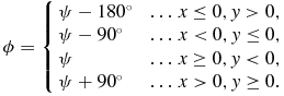
Assuming that the native longitude, φ, is normalised in the range [ − 180°, 180°), then
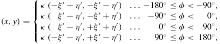 \begin{eqnarray}
\hspace*{-10pt}(x,y) = \left\lbrace \begin{array}{l@{\hspace{8.0pt}}l@{\hspace{3.0pt}}r@{\hspace{3.0pt}}l@{\hspace{2.0pt}}r}\kappa \, (-\xi ^{\prime }+\eta ^{\prime },-\xi ^{\prime }-\eta ^{\prime }) & \ldots & -180\hbox{$^\circ $}& \le \phi < & -90\hbox{$^\circ $}, \\
\kappa \, (\hphantom{+}\xi ^{\prime }+\eta ^{\prime },-\xi ^{\prime }+\eta ^{\prime }) & \ldots & -90\hbox{$^\circ $}& \le \phi < & 0\hbox{$^\circ $}, \\
\kappa \, (\hphantom{+}\xi ^{\prime }-\eta ^{\prime },+\xi ^{\prime }+\eta ^{\prime }) & \ldots & 0\hbox{$^\circ $}& \le \phi < & 90\hbox{$^\circ $}, \\
\kappa \, (-\xi ^{\prime }-\eta ^{\prime },+\xi ^{\prime }-\eta ^{\prime }) & \ldots & 90\hbox{$^\circ $}& \le \phi < & 180\hbox{$^\circ $}, \end{array} \right.
\end{eqnarray}
\begin{eqnarray}
\hspace*{-10pt}(x,y) = \left\lbrace \begin{array}{l@{\hspace{8.0pt}}l@{\hspace{3.0pt}}r@{\hspace{3.0pt}}l@{\hspace{2.0pt}}r}\kappa \, (-\xi ^{\prime }+\eta ^{\prime },-\xi ^{\prime }-\eta ^{\prime }) & \ldots & -180\hbox{$^\circ $}& \le \phi < & -90\hbox{$^\circ $}, \\
\kappa \, (\hphantom{+}\xi ^{\prime }+\eta ^{\prime },-\xi ^{\prime }+\eta ^{\prime }) & \ldots & -90\hbox{$^\circ $}& \le \phi < & 0\hbox{$^\circ $}, \\
\kappa \, (\hphantom{+}\xi ^{\prime }-\eta ^{\prime },+\xi ^{\prime }+\eta ^{\prime }) & \ldots & 0\hbox{$^\circ $}& \le \phi < & 90\hbox{$^\circ $}, \\
\kappa \, (-\xi ^{\prime }-\eta ^{\prime },+\xi ^{\prime }-\eta ^{\prime }) & \ldots & 90\hbox{$^\circ $}& \le \phi < & 180\hbox{$^\circ $}, \end{array} \right.
\end{eqnarray}
 \begin{eqnarray}
(\xi ^{\prime },\eta ^{\prime }) = (\xi -45\hbox{$^\circ $}, \eta -90\hbox{$^\circ $}) ,
\end{eqnarray}
\begin{eqnarray}
(\xi ^{\prime },\eta ^{\prime }) = (\xi -45\hbox{$^\circ $}, \eta -90\hbox{$^\circ $}) ,
\end{eqnarray} $\kappa = \sqrt{2}/2$
. The native latitude that divides the equatorial and polar zones is θ× = sin −1(2/3). In the equatorial zone, | θ | ≤ θ×, we have
$\kappa = \sqrt{2}/2$
. The native latitude that divides the equatorial and polar zones is θ× = sin −1(2/3). In the equatorial zone, | θ | ≤ θ×, we have
 \begin{eqnarray}
\xi &=& \psi ,\\
\end{eqnarray}
\begin{eqnarray}
\xi &=& \psi ,\\
\end{eqnarray}
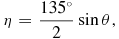 \begin{eqnarray}
\eta &=& \frac{135\hbox{$^\circ $}}{2} \sin \theta ,
\end{eqnarray}
\begin{eqnarray}
\eta &=& \frac{135\hbox{$^\circ $}}{2} \sin \theta ,
\end{eqnarray}
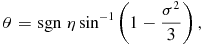
and in the polar zones, where | θ | > θ×,
 \begin{eqnarray}
\xi &=& 45\hbox{$^\circ $}+ (\psi - 45\hbox{$^\circ $}) \,\sigma ,\\
\end{eqnarray}
\begin{eqnarray}
\xi &=& 45\hbox{$^\circ $}+ (\psi - 45\hbox{$^\circ $}) \,\sigma ,\\
\end{eqnarray}
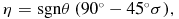 \begin{eqnarray}
\eta &=& {\rm sgn}\theta \, ( 90\hbox{$^\circ $}- 45\hbox{$^\circ $}\sigma ) ,
\end{eqnarray}
\begin{eqnarray}
\eta &=& {\rm sgn}\theta \, ( 90\hbox{$^\circ $}- 45\hbox{$^\circ $}\sigma ) ,
\end{eqnarray}
 \begin{eqnarray}
\psi &=& (\phi + 180\hbox{$^\circ $}) \pmod {90\hbox{$^\circ $}} ,\\
\end{eqnarray}
\begin{eqnarray}
\psi &=& (\phi + 180\hbox{$^\circ $}) \pmod {90\hbox{$^\circ $}} ,\\
\end{eqnarray}
 \begin{eqnarray}
\sigma &=& \sqrt{3 (1 - |\sin \theta \,|\,)} .
\end{eqnarray}
\begin{eqnarray}
\sigma &=& \sqrt{3 (1 - |\sin \theta \,|\,)} .
\end{eqnarray}
2.2 Deprojection equations
To invert the projection equations, first compute (ξ, η) via
 \begin{eqnarray}
(\xi , \eta ) = (\xi ^{\prime }+45\hbox{$^\circ $}, \eta ^{\prime }+90\hbox{$^\circ $}) ,
\end{eqnarray}
\begin{eqnarray}
(\xi , \eta ) = (\xi ^{\prime }+45\hbox{$^\circ $}, \eta ^{\prime }+90\hbox{$^\circ $}) ,
\end{eqnarray}
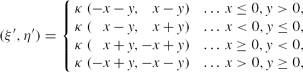 \begin{eqnarray}
(\xi ^{\prime },\eta ^{\prime }) = \left\lbrace \begin{array}{l@{\hspace{8.0pt}}l@{\hspace{3.0pt}}l}\kappa \, (-x-y,\hphantom{+}x-y) & \ldots & x \le 0, y > 0 , \\
\kappa \, (\hphantom{+}x-y,\hphantom{+}x+y) & \ldots & x < 0, y \le 0 , \\
\kappa \, (\hphantom{+}x+y,-x+y) & \ldots & x \ge 0, y < 0 , \\
\kappa \, (-x+y,-x-y) & \ldots & x > 0, y \ge 0 , \end{array} \right.
\end{eqnarray}
\begin{eqnarray}
(\xi ^{\prime },\eta ^{\prime }) = \left\lbrace \begin{array}{l@{\hspace{8.0pt}}l@{\hspace{3.0pt}}l}\kappa \, (-x-y,\hphantom{+}x-y) & \ldots & x \le 0, y > 0 , \\
\kappa \, (\hphantom{+}x-y,\hphantom{+}x+y) & \ldots & x < 0, y \le 0 , \\
\kappa \, (\hphantom{+}x+y,-x+y) & \ldots & x \ge 0, y < 0 , \\
\kappa \, (-x+y,-x-y) & \ldots & x > 0, y \ge 0 , \end{array} \right.
\end{eqnarray} $\kappa = \sqrt{2}/2$
as before. Then
$\kappa = \sqrt{2}/2$
as before. Then
 \begin{eqnarray}
\phi = \left\lbrace \begin{array}{l@{\hspace{8.0pt}}l@{\hspace{3.0pt}}l}\psi - 180\hbox{$^\circ $}& \ldots & x \le 0, y > 0 , \\
\psi - 90\hbox{$^\circ $}& \ldots & x < 0, y \le 0 , \\
\psi & \ldots & x \ge 0, y < 0 , \\
\psi + 90\hbox{$^\circ $}& \ldots & x > 0, y \ge 0 . \end{array} \right.
\end{eqnarray}
\begin{eqnarray}
\phi = \left\lbrace \begin{array}{l@{\hspace{8.0pt}}l@{\hspace{3.0pt}}l}\psi - 180\hbox{$^\circ $}& \ldots & x \le 0, y > 0 , \\
\psi - 90\hbox{$^\circ $}& \ldots & x < 0, y \le 0 , \\
\psi & \ldots & x \ge 0, y < 0 , \\
\psi + 90\hbox{$^\circ $}& \ldots & x > 0, y \ge 0 . \end{array} \right.
\end{eqnarray}
In the equatorial zone where | η | ⩽ 45°,
 \begin{eqnarray}
\psi &=& \xi , \\
\end{eqnarray}
\begin{eqnarray}
\psi &=& \xi , \\
\end{eqnarray}
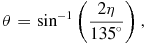 \begin{eqnarray}
\theta &=& \sin ^{-1} \left( \frac{2 \eta }{135\hbox{$^\circ $}} \right) ,
\end{eqnarray}
\begin{eqnarray}
\theta &=& \sin ^{-1} \left( \frac{2 \eta }{135\hbox{$^\circ $}} \right) ,
\end{eqnarray}
 \begin{eqnarray}
\psi &=& 45\hbox{$^\circ $}+ (\xi - 45\hbox{$^\circ $}) / \sigma ,\\
\end{eqnarray}
\begin{eqnarray}
\psi &=& 45\hbox{$^\circ $}+ (\xi - 45\hbox{$^\circ $}) / \sigma ,\\
\end{eqnarray}
 \begin{eqnarray}
\theta &=& {\rm sgn}\;\eta \sin ^{-1} \left( 1 - \frac{\sigma ^2}{3} \right) ,
\end{eqnarray}
\begin{eqnarray}
\theta &=& {\rm sgn}\;\eta \sin ^{-1} \left( 1 - \frac{\sigma ^2}{3} \right) ,
\end{eqnarray}
 \begin{eqnarray}
\sigma = \frac{90\hbox{$^\circ $}- |\,\eta \,|}{45\hbox{$^\circ $}} .
\end{eqnarray}
\begin{eqnarray}
\sigma = \frac{90\hbox{$^\circ $}- |\,\eta \,|}{45\hbox{$^\circ $}} .
\end{eqnarray}
3 IMPLEMENTATION NOTES
This section records some problems that may arise in implementing these equations at the highest levels of numerical precision.
3.1 Equation (8)
A subtle problem arises from the innocent looking Equation (8) when φ < 0 but very close to zero; in this case, ψ should be just slightly less than 90°. However, due to the loss of numerical precision that results from adding 180° to φ, or simply from taking the modulo 90° (e.g. via the fmod function in C), application of Equation (8) may instead yield ψ = 0, effectively as though φ = 0. After computing (ξ′, η′), the problem then arises by selecting the φ < 0 option in Equation (2) when in fact the φ = 0 option would be the appropriate one in this case.
A simple solution is, when computing ψ, also to recompute φ as (ϕ + 180°) − 180° as this will apply the same numerical rounding to φ as occurred in computing ψ, thereby ensuring selection of the appropriate option in Equation (2).
3.2 Equations (9) and (16)
Numerical precision may be lost in Equations (9) and (16) when σ is very close to zero, which unfortunately occurs in the neighbourhood of the reference point. This precision may be recovered by rewriting Equation (16) using the small angle trigonometric formulae, which allows the expression in σ2 to be replaced by one in σ. Thus,
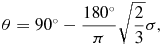 \begin{eqnarray}
\theta = 90\hbox{$^\circ $}- \frac{180\hbox{$^\circ $}}{\pi } \sqrt{\frac{2}{3}} \sigma ,
\end{eqnarray}
\begin{eqnarray}
\theta = 90\hbox{$^\circ $}- \frac{180\hbox{$^\circ $}}{\pi } \sqrt{\frac{2}{3}} \sigma ,
\end{eqnarray}
 \begin{eqnarray}
\sigma = (90\hbox{$^\circ $}- \theta ) \frac{\pi }{180\hbox{$^\circ $}} \sqrt{\frac{3}{2}},
\end{eqnarray}
\begin{eqnarray}
\sigma = (90\hbox{$^\circ $}- \theta ) \frac{\pi }{180\hbox{$^\circ $}} \sqrt{\frac{3}{2}},
\end{eqnarray}
4 CONCLUSION
XPH has been implemented in version 4.18 and later versions of WCSLIB (Calabretta 1995), which is distributed under the Lesser GNU General Public License (LGPL).
As of version 4.3, WCSLIB has included a utility program that converts 1D HEALPix pixelisation data stored in a variety of forms in FITS, including ring or nested organisation in a binary table extension, into a 2D primary image array optionally with HPX or XPH coordinate representation.
ACKNOWLEDGEMENTS
We wish to thank Dr. Paddy Leahy of the Jodrell Bank Centre for Astrophysics for motivating this work.
The Australia Telescope is funded by the Commonwealth of Australia for operation as a National Facility managed by CSIRO.

