


1. Introduction
The advent of high-energy short-pulse lasers poses new problems related to radiation protection in the laser facilities. The radiation generated in experiments using multipetawatt laser systems leads to prompt doses and potentially to the activation of the materials, within the experimental area. This issue is common to many PW and multi-PW laser facilities, which are operating or under construction around the world [Reference Danson, Hillier, Hopps and Neely1]. Very-high-energy laser facilities dedicated to inertial confinement fusion also share this problem since they are usually coupled to high-intensity short-pulse lasers. Such lasers are in operation at NIF [Reference Haan, Pollaine and Lindl2] (the ARC laser system), at LMJ [Reference Ebrardt and Chaput3] (the Petal laser system [4, Reference Batani, Koenig and Miquel5]), at the University of Rochester (Omega EP) [Reference Guardalben, Barczys, Kruschwitz, Spilatro, Waxer and Hill6], at the University of Osaka in Japan (LFEX) [Reference Arikawa, Kojima and Morace7], at the Shen Guang-II laser facility in Shanghai [Reference Zhu, Li, Zhu, Ma, Lu and Lin8], and on the laser Orion in the United Kingdom [Reference Hopps, Oades and Andrew9]. The construction of such systems, delivering kilojoule energies in picosecond times, is motivated by the need for probing matter using secondary sources of X-rays or protons over a time range of picosecond and by the need for isochorically heating dense materials.
It becomes then imperative to evaluate whether the high fluxes of secondary radiation (X-rays and protons) produced by petawatt shots on the target represent a serious issue for the activation of the materials in the chamber. This is an important question with deep implications on one side on the safety rules, which may need to be applied at the facility, and on the other side on the response of the chamber and the diagnostic instruments: their aging and their survivability.
The major hazard is the high energy of laser-accelerated particles, electrons, photons, and ions, which are propagating out of the interaction zone and may activate the elements of target support, diagnostics, experimental chamber, and even elements outside the chamber. Two typical operational modes are considered in this paper. In the first one, the laser is focused on target to produce hard X-rays for X-ray radiography (TS1). In the second one, it is used to produce high-energy protons (TS2). For each source, we estimate the flux of energetic particles and their energy spectrum produced in laser target interactions, and then we evaluate their activation effect on the interaction with diagnostic equipment and chamber elements.
This paper is organized as follows. Section 2 describes the general approach and the methodology of the activation calculations, which consist of two main parts: characterization of the source of energetic particles from the laser target interaction and the activation of the environment materials after the laser shot. The challenges related to the first part, presented in Section 3, are in the strongly nonlinear physics of laser-matter interaction at relativistic laser intensities that require large-scale numerical calculations. The main issue related to the second task, presented in Section 4, is the necessity to consider the representative geometry of the experimental chamber and diagnostic instruments.
The methodology developed in this paper allows for the evaluation of the radiological effects induced by the operation of a high-power laser facility, a question that has received little attention until now despite many new PW laser facilities that are nowadays entering into operation. Our approach is general and may be applied for the design of experiments with any high-power laser system already operational or still under construction in various countries.
2. Calculation Methodology
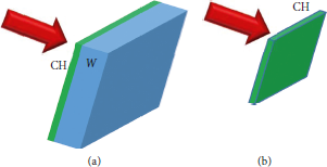
The safe operation of a laser facility requires the determination of the maximum activity of radioelements that will be produced during the whole cycle of the facility operation and the prediction of their lifetime. The elements that should be precisely identified come from the activation of the target itself and from the materials located in the target chamber, on its walls, in the concrete shield, and in all other elements of the experimental hall. Activation is mainly induced by two sources: the X-rays produced by energetic electrons through the Bremsstrahlung process in thick targets made of a heavy element (source TS1) and the protons accelerated to high energies from thin targets made of light elements (source TS2). These two kinds of targets, used for photon [Reference Martynenko, Pikuz and Skobelev10] and proton sources [Reference Raffestin, Blanchot and Boutoux11–Reference Badziak and Domański13], shown in Figure 1, are commonly used in experiments for X-ray radiography [Reference Morace, Fedeli and Batani14], proton radiography [Reference Volpe, Batani and Vauzour15], opacity measurements, target heating [Reference Santos, Debayle and Nicolaï16], and for producing nuclear reactions [Reference Margarone, Morace and Bonvalet17].
Typical targets used in the simulations of the photon (TS1) and proton (TS2) sources.
The calculation of the nuclide inventory proceeds in two steps. The first step consists of the estimation of the proton and electron sources resulting from the interaction of the laser pulse with a solid target. For this, we use a particle-in-cell (PIC) code [Reference Sentoku and Kemp18] developed for the simulation of laser-plasma interactions, which has been validated by comparison with many experimental results. In the case of the TS2 source, the proton characteristics—the energy spectrum and the divergence—can be directly calculated with the PIC code as the size of the proton source, of about 100 μm, comparable to the laser focal spot, can be fully modeled within the simulation box. Then, the proton beam characteristics are transferred to the second step to simulate the material activation by using the Monte Carlo codes as MCNP [19], FISPACT-II [20], and GEANT4 [Reference Agostinelli, Allison and Amako21] developed by the accelerator community.
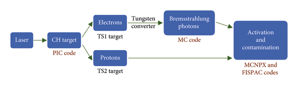
The methodology is more complicated in the case of the TS1 source, where an additional step consists in the calculation of high-energy photons. As the Bremsstrahlung cross section is relatively low, the thickness of the converter target needs to be of millimeter size, which is prohibitive (too time-consuming) for PIC simulations. On the other side, the collective effects in photon production are not important as the density of fast electrons decreases rapidly as they propagate away from the laser focal spot. Thus, for the calculations of photon production, we used the Monte Carlo code GEANT4 [Reference Agostinelli, Allison and Amako21]. A tungsten target has been used in this simulation as this is a typical convertor used in many radiography experiments. The electron beam characteristics, calculated in the first step with the PIC code, are injected in GEANT4 for the calculation of energy and angular distributions of X-rays produced by Bremsstrahlung, and of secondary electrons and positrons. The characteristics of the emitted energetic electrons and photons are then used as inputs to the MCNP and FISPACT-II simulations for material activation. The whole chain of the calculation is shown in Figure 2.
Scheme of calculations for the determination of the prompt dose and activation.
The overall methodology for calculating the sources of protons and electrons using PIC simulations and using these as primary source terms in Monte Carlo codes (MCNPX, GEANT4, etc.) for the evaluation of secondary emission is a rigorous method already used in previous studies such as Clark et al. [Reference Clark, Kamperidis, Papadogiannis and Tatarakis22].
3. Characterization of the Electron and Proton Fluxes
3.1. Description of the Code PICLS
Particle-in-cell (PIC) codes are widely used for modeling the interaction of high-intensity laser pulses with solid and gaseous targets. By using the full kinetic description of the charged particle dynamics coupled to Maxwell’s equations for electromagnetic fields, such codes provide a detailed description of the laser energy deposition and of the transport of energetic electrons in dense plasmas. The major issue in PIC simulations is the significant computation cost due to the very large number of macroparticles and the spatial grid resolution needed to resolve the Debye length and plasma period. Nevertheless, the last generation of PIC codes is capable of performing large-scale numerical simulations on the timescale of many picoseconds in dense plasmas.
PICLS is a 1D/2D/3D relativistic PIC code. In its full version, it accounts for particle collisions, radiation emission and transport, and field and impact ionization allowing to describe plasmas in a large range of temperatures and densities. The collision model in PICLS is based on the probabilistic approach [Reference Takizuka and Abe23]. It fully conserves energy in individual collisions and also conserves on average the momentum of particles. PICLS offers a possibility to model large density gradients by using variable weight particles. The ionization module is based on the Ammosov–Delone–Krainov model [Reference Ammosov, Delone and Krainov24] for the field ionization and the Thomas Fermi model, the Saha model, or the impact ionization model [Reference Lotz25] for the collisional ionization.
3.2. Target Parameters
A simplified noncollisional 2D version of PICLS was used in the present study as we were interested only in the particles with energies above 1 MeV able to induce nuclear reactions, which are intrinsically less collisional. The targets considered are plane foils as shown in Figure 1.
The TS1 target is made of 2 mm thick and 4 × 4 cm2 wide bulk tungsten with its front side covered with 20 μm of plastic (CH). Only the central part (200 μm wide and 10 μm thick, made of plastic) was modeled with the PIC code.
The TS2 target is made of a 20 μm thick and 1 × 1 mm2 wide plastic CH. Only the central part which is 200 μm wide and 10 μm thick was modeled. We verified that the charged particles, electrons, and protons were emitted from a zone smaller than the size of the simulation box.
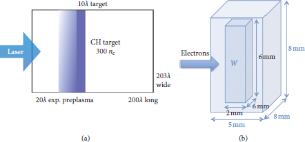
The simulation box is presented in Figure 3(a). The simulation box is 200 μm long and 203 μm wide. The solid target is located 70 μm from the left boundary. The plastic layer was modeled as a two-ion species plasma: protons with mass-to-charge ratio 1 and carbons with mass-to-charge ratio 2. The initial electron density of the target was 3.3 1023 cm−3, which corresponds to the density of solid plastic. This is 300 times the critical density of the incident laser beam. The initial temperatures are set to zero: T e = T i = 0 in order to ensure that the plasma is frozen before the high-intensity laser pulse reaches the target. As the target is then heated to keV by the laser pulse, this choice does not affect the collisionless absorption processes.
(a) PICLS simulation setup. (b) Simulation setup for the Monte Carlo simulations.
The cell size used in the PIC simulations is 14.7 nm in both directions and the time step is 48.5 as 6 carbon ions, 12 protons, and 48 electrons were initialized in each plasma cell. The total number of macroparticles is therefore 1.8 billions.
The preplasma induced by the prepulse, always associated with the PW laser pulse, was modeled with an exponential function n e ∝ exp(−x/L n ) with characteristic length L n = 3 μm. The shape of the preplasma, induced by the prepulse, largely impacts the electron generation and consequently the emission of particles and radiation. In this respect, the small 3 μm scalelength chosen in our simulations corresponds to the preplasma produced by a laser system with a good contrast, of the order of 109–1010, as it is achieved in several laser systems today.
3.3. Laser Pulse Characteristics
In this paper, we mainly limit our analysis to results obtained with a 0.5 ps FWHM pulse duration at a wavelength of 1.053 μm, this being the most representative for large-scale facilities such as ARC, PETAL, and LFEX. Longer pulse durations are considered in Section 3.7. The range of pulse energies from 0.2 to 3.5 kJ corresponds to the typical range of operation of high-energy short-pulse lasers.
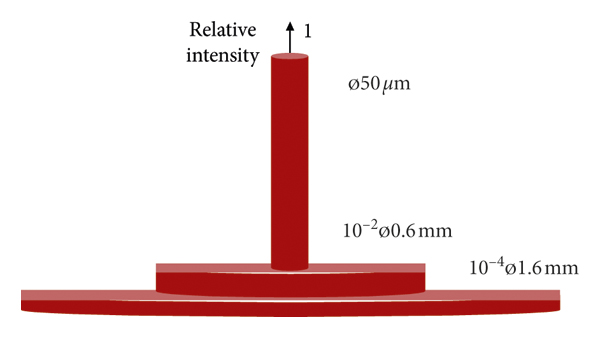
The characteristics of energetic particles depend mainly on laser intensity on the target, and, therefore, on the focusing conditions. Here, we assumed a “realistic” laser spot made of a central laser spot and intensity wings as these are always present in high-energy short-pulse laser systems. The intensity distribution is given in Figure 4. Again, this is a qualitative representation of the intensity distribution in systems like LFEX or PETAL. Approximately 40% of the laser pulse energy is contained in the main spot of 50 μm FWHM. Most of the remaining part with intensity 100 times lower is distributed over a 600 μm FWHM zone. In the simulations, we considered only the central part of the laser pulse as only this part is creating the energetic particles that produce activation. Consequently, for the pulse energy range from 0.2 to 3.5 kJ, the maximum laser intensities in the focal spot vary from 8 × 10¹⁸ W/cm2 to 1.4 × 10²⁰ W/cm2 (assuming a top-hat intensity distribution).
Spatial profile of the focal spot.
In the simulations, the temporal and spatial laser profiles are modeled with truncated Gaussian functions. The laser pulse has a linear polarization in the simulation plane at normal incidence. The laser profile is Gaussian in the longitudinal and transverse directions. In the transverse direction, the Gaussian profile is limited by the transverse simulation box size, while in the longitudinal direction, the total duration of the pulse is 2 times its FWHM. This is technically implemented by appropriately choosing the corresponding laser amplitude on the left side boundary of the simulation box where the laser enters. The total duration of the laser pulse, which enters the simulation box from the left boundary, is therefore 1 ps.
To perform a parameter scan in a reasonable time, it was necessary to find a compromise when choosing the simulation parameters. At very high laser energy and with a focal spot of 50 μm, the width of the simulation box required to avoid boundary effects strongly limits the possibility to perform a large parameter scan. We have, therefore, chosen to perform a set of simulations with a focal spot of 30 μm in a smaller simulation box. The comparison with the 50 μm focal spot is discussed in Section 3.6 (a focal spot of 30 μm is also interesting since this has been measured on PETAL although not during the routine operation at maximum laser energy).
The boundary conditions are periodical in the transverse direction (y) and absorbing in the direction of laser propagation (x). In order to retrieve the total number of emitted protons, we use the conservative estimate that the source size in the z-direction is given by the laser FWHM. The results presented below cannot precisely predict experimental results. In particular, the maximum proton energy can be overestimated by a few ten percent. Nevertheless, they are sufficient for subsequent activation calculations. Indeed, by overestimating the energies and the number of energetic particles (in a reasonable fashion), we get a “worst case” scenario, which is interesting in order to establish the safety rules of facilities.
3.4. Electron Fluxes
The electron angular and energy distributions for the laser energies 1 and 3.5 kJ are presented in Figure 5. The spectra for smaller energies are similar at a lower temperature and a lower energy cutoff.
(a) Energy and (b) angular distributions of electrons generated in the focal spot simulated by the code PICLS for a total laser energy of 1 (red) and 3.5 kJ (blue).
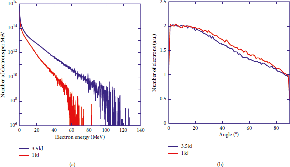
The electron angular distribution appears to be not very sensitive to the laser energy. The variation between the laser propagation axis and the perpendicular plane is less than a factor of 2. On the other hand, the electron energy distribution has an exponential shape characterized by a hot electron temperature T he and the cutoff energy ε e max.
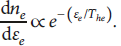
In agreement with the theory and with experimental observations, the maximum electron energy, the hot electron temperature, and the efficiency of transformation of laser energy into hot electrons, η h , depend on the incident laser intensity [Reference Wilks, Kruer, Tabak and Langdon26–Reference Green28] as follows:
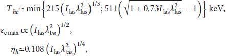
where λ las is the laser wavelength in microns and I las is the laser intensity in units of 1018 W/cm2. The second term in the formula for hot electron temperature represents the well-known ponderomotive scaling. As in our simulations, the pulse duration and the laser focusing conditions were fixed, and these relations represent the dependence of hot electron characteristics on the laser pulse energy. The characteristics of accelerated electrons are presented in Table 1.
3.5. Proton Fluxes
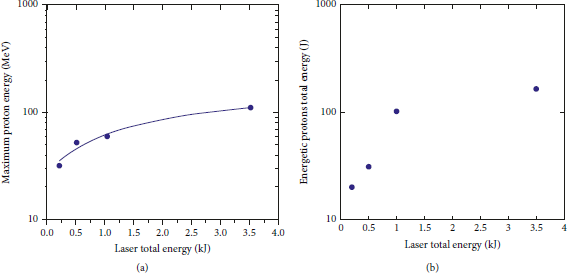
Figure 6 shows the angular and energy distribution of protons for the laser energies of 3.5 kJ. Proton emission is strongly collimated (unlike electrons) in agreement with the TNSA mechanism, which dominates at these laser intensities [Reference Passoni, Perego, Sgattoni and Batani29, Reference Malka, Guemnie-Tafo and Ewald30]. The emission angle decreases with the increase in proton energy and is not very sensitive to the laser energy under the conditions studied here. The energy distribution can be approximated by an exponential function as follows:
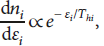
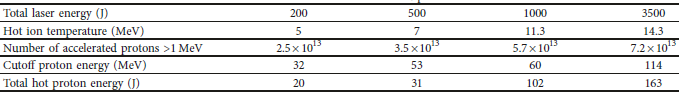
with effective temperature T hi and a sharp cutoff energy ε i max. The maximum proton energies, their effective temperature T hi , and the total energy carried with the energetic ions measured in these simulations are shown in Table 2 and in Figure 7 as a function of the total laser energy. The proton energy spectra and angular distributions were measured after 2.3 ps when their maximum energy is saturated (with a gain of less than 2% in the last 300 fs).
(a) Energy and (b) angular distributions of the protons simulated by the code PICLS for a total laser energy of 3.5 kJ.
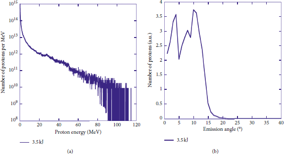
Variation in the maximum proton energy (a) and the total proton energy (b) as a function of total incident laser energy.
In the case of thin plastic targets (TS2), in addition to protons, carbon ions will also be accelerated. However, their number is much smaller than that of protons (as confirmed by the analysis of the traces on the Thomson parabola performed in a recent experiment [Reference Raffestin, Blanchot and Boutoux11]) and their energy per nucleon is smaller because they are accelerated at later times than protons, i.e., at times when the electric field is already reduced (see, for instance, Bychenkov et al. [Reference Bychenkov, Novikov, Batani and Tikhonchuk31]). Hence, they have a minor effect on the prompt dose and, indeed, they will almost not contribute to activation, which is mainly produced by neutrons which, being not charged, interact easily with the nuclei of the target material. Such neutrons are either induced by protons or by hard X-ray photons, as shown later in the text.
The characteristics of protons and electrons generated in our PIC simulations are in agreement with previous measurements and scaling reported in other publications [Reference Beg, Bell and Dangor27–Reference Malka, Guemnie-Tafo and Ewald30].
3.6. Case of a Larger Focal Spot
Most of our simulations were performed with a focal spot of 30 μm in order to scan a larger parameter domain. We also made simulations with a larger focal spot of 50 μm in order to verify the scaling. As the intensities with the reduced focal spot are approximately 2.5 times higher, the results of our simulations can partially overestimate the production of energetic electrons and ions.
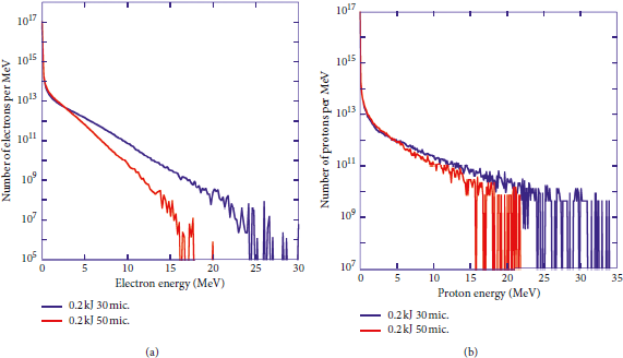
To demonstrate this effect, we have compared the results obtained with the focal spots of 50 and 30 μm for the same laser energy of 200 J. Figure 8 represents the electron and proton energy spectra for the two considered focal spot sizes. The increase in the intensity by a factor of (50/30)2 leads to higher cutoff energies of electrons and protons. However, the total number of energetic particles with energies larger than 1 MeV depends on the total laser energy and it remains approximately the same.
Comparison of electron (a) and proton (b) energy spectra for a focal spot of 30 μm and a focal spot of 50 μm for the same laser energy of 200 J and a pulse duration of 0.5 ps.
3.7. Case of Longer Pulse Durations
We have considered a pulse duration of 0.5 ps. Nevertheless, a longer pulse duration can be used, because in some cases, it can maximize protons and X-ray emissions. It is therefore important to study the influence of pulse duration on fast particle generation.
In this context, we have simulated the case of a total laser energy of 1 kJ with a pulse duration of 1 ps. The intensity on target is thus divided by two compared to the cases presented in the previous section. A comparison of the electron and proton energy spectra for the pulse durations of 500 fs and 1 ps is shown in Figure 9. As one can see, the trends observed with a shorter pulse duration are not significantly affected except for the reduced cutoff energy.
Comparison of electron (a) and proton (b) energy spectra for the pulse durations of 0.5 and 1 ps for 1 kJ laser energy.
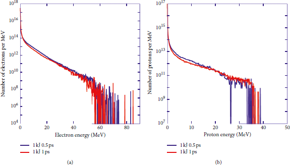
Therefore, in this regime of high laser energies, the electron and proton energy spectra are not very sensitive to the doubling of the pulse duration, while keeping the laser energy constant. The spectra obtained with a pulse duration of 0.5 ps are therefore representative and pertinent.
4. Monte Carlo Simulations of Photon Production in a Tungsten Target
Tungsten is commonly used as a Bremsstrahlung converter. We used the Monte Carlo code GEANT4 [Reference Agostinelli, Allison and Amako21] to simulate the transport and the interaction of laser-generated hot electrons within tungsten in three spatial dimensions. Our GEANT4 simulations were coupled to PENELOPE (PENetration and Energy LOss of Positrons and Electrons) physics libraries [Reference Sempau, Acosta, Baro, Fernández-Vare and Salvat32] that make use of low-energy models for electron and photon transport including Compton scattering, photoelectric effect, Rayleigh scattering, Bremsstrahlung emission, ionization, pair production, and positron annihilation. The use of PENELOPE models provides highly reliable results for energies down to a few hundred eV and can be used up to 1 GeV [Reference Sempau, Fernández-Varea and Acosta33]. It enables, first, a precise treatment of electromagnetic showers and interactions at the keV scale, and second, the description of atomic deexcitation processes such as fluorescence X-rays. A tracking cutoff value of 1 μm was chosen, which corresponds to an energy threshold of nearly 1 keV for both electrons and photons. This means that, below this limit, we do not simulate the transport and reactions of particles longer.
4.1. Source Initialization
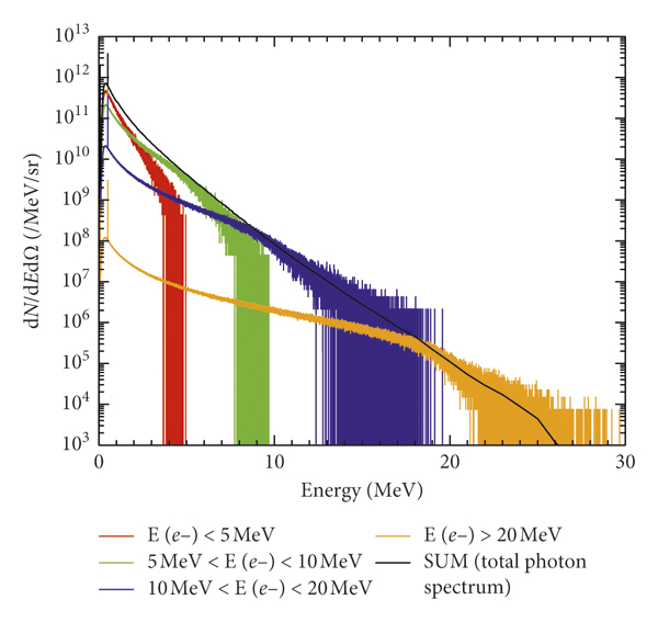
The target considered in the GEANT4 simulations, according to Figure 3, was a parallelepiped made of tungsten with dimensions 6 × 6 × 2 mm3. We described the electron source by using 2D Gaussian spatial distribution with a standard deviation of 50 μm, in agreement with the laser focal spot size. Electrons were injected taking into account their angular distribution as calculated from the PIC simulation. They were injected along the target normal, i.e., the symmetry axis of the angular distribution was aligned with the target normal (which in our specific case also coincides with the direction of the incident laser beam). The used computational volume was also a parallelepiped with dimensions 8 × 8 × 5 mm3. The graphical representation of the interaction geometry is shown in Figure 3(b). The laser-produced electrons calculated with PICLS simulations were used as the input for calculations of the electron transport and Bremsstrahlung emission of photons in the target. Therefore, to describe the characteristics of the electron source, we directly used the electron energy and angular distributions given in Figure 5 (panels a and b, respectively). Since the input electron energy spectra cover a dynamical range over 1012 orders of magnitude, we would need to simulate a very large number of particles (1010 1011) in order to obtain a spectrum of photons, which is not strongly affected by fluctuations, especially in the high-energy tail. However, the simulation was computation-time prohibitive in this case (109 particles correspond to a computation of 1 day). To overcome this problem, considering that there are no collective effects in bremsstrahlung emission, we performed independent simulations by considering successive partial incident electron energy ranges with a reduced number of particles (108). Each contribution was then normalized to the number of incident electrons in the considered energy range as given in the PICLS simulations. By summing all the normalized contributions, the full-photon spectrum has been reconstructed at the keV scale with negligible statistical fluctuations from 10 keV to several hundreds of MeV. For instance, Figure 10 illustrates this method applied to the determination of the energy spectrum of photon emission from the rear side of the target (transmitted photons) for the laser pulse energy of 200 J.
Energy spectra of photon emission from the rear side of the target for a laser energy of 200 J. We performed normalized simulations for 4 partial incident electron energy bins (colored curves), and then we summed them to obtain the full-photon spectrum at the keV scale (black curve).
4.2. Photon Fluxes
In our simulations, we were able to track all primary and secondary particles inside the computational volume. The energy and angular distribution of electrons, photons, and positrons are calculated at the front and rear side of the tungsten target. In general, we can notice that many incident electrons are reflected while most of the electrons penetrating the target are absorbed. In addition, some electron-positron pairs are produced by the energetic photons. The positrons interact with the electron cloud of neighbor atoms and produce the 511 keV secondary photon peak. At low energy, discrete fluorescence peaks appear in the energy spectra. Their origin is due to the hot electrons penetrating into the target material and producing inner shell collisional ionization. Such inner holes are then filled by radiative recombination, emitting the characteristic lines of the target material. In the case of tungsten, K α and K β lines are at about 59 and 69 keV, respectively. Notice that, just after the K β peaks, the systematic fall in the spectra can be explained by the rise of the X-ray absorption in the target above the K-edge energy, which is equal to the binding energy of the K-shell electron.
Figure 11 presents the photon energy spectra emitted from the rear and the front target surfaces for the laser pulse energies of 200, 500, 1000, and 3500 J. The effect of the self-absorption inside the target is particularly important for the transmitted photons below 1 MeV. However, in the context of the activation study, we are mostly interested in the more energetic photons. In this energy range (above 1 MeV), similarly to the electron and proton spectra, the photon energy distribution can be characterized by an exponential function with a sharp cutoff. In general, this energy cutoff is slightly higher for transmitted photons than for the reflected ones. The photon distributions obtained for higher laser energies up to 3.5 kJ have similar characteristics to that obtained for higher photon temperature.
Energy spectra of photon emission from (a) the rear (transmitted photons) and (b) front side (reflected photons) of the target for laser energies of 200, 500, 1000, and 3500 J.
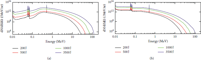
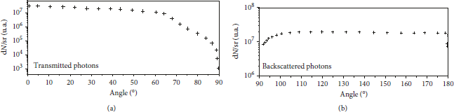
Figure 12 shows the angular distribution of the backscattered and transmitted photons. In particular, for transmitted photons, the angular distribution is almost isotropic up to about 70° from the propagation axis of the electron beam. For the larger angles, photon propagation is more parallel to the target plane, and hence, the intensity drops rapidly because of absorption. Reflected photons also have an angular distribution, which is rather isotropic again dropping as the direction approaches the plane of the target surface.
Angular distribution of transmitted and backscattered photons for a laser energy of 3500 J.
The summary of Monte Carlo simulations of the characteristics of the secondary emissions is presented in Table 3 and in Figure 13. We observe the following:
-
(i) The fraction of the reflected electrons decreases from 50% at the lowest laser energy to 30% at the highest energy. The effective temperature of backscattered electrons is slightly smaller than the temperature of incident electrons due to their collisions with the electrons in the target.
-
(ii) The fraction of transmitted particles increases up to 5% at the maximum energy, which remains rather small because of a large thickness of the tungsten sample.
-
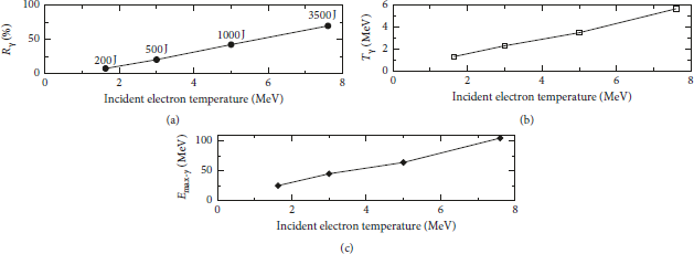
(iii) The number of generated and transmitted photons increases. This reflects an increase in the electron/photon conversion ratio R γ , as shown in Figure 12(a). It increases from 7 to 70% in the considered laser energy range.
-
(iv) The photon mean energy increases as shown in Figure 12(b). The effective temperature of the transmitted photons T γ is by a factor of 10–20% smaller than the corresponding hot electron temperature due to the electron cooling and production of secondary electrons in the collisions with tungsten atoms. However, it follows the same trend as a function of the laser energy.
-
(v) The photon maximum energy E max−γ increases as shown in Figure 13(c). It is approximately the same as the hot electron cutoff energy (see Table 2).
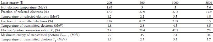
In the framework of our study of activation, the electron/photon conversion ratio R γ is calculated assuming electron energies above 1 MeV and the temperature of transmitted photons T γ is measured by using an exponential fit of the energy spectra of transmitted photons above 1 MeV.
Dependence on hot electron temperature of (a) the electron/photon conversion ratio R γ in the tungsten target, (b) the temperature of high-energy photons T γ (E > 1 MeV) transmitted through the tungsten target, and (c) their maximum energy E max−γ .
The mean energy and the number of photons emitted in the backward direction are smaller than those in the forward direction for all hot electron temperatures considered here.
Therefore, we assume, as a maximizing hypothesis, that backscattered photons have the same characteristics of transmitted photons. The number of emitted positrons is small compared to the number of electrons having the same energy and their contribution to activation will be neglected.
Of particular interest is the scaling of the conversion efficiency of electrons to photons in the GEANT4/PENELOPE simulations with laser energy. Our estimates are in line with experimental results obtained at smaller laser energies. For instance, conversion rates of few percent in laser systems with ∼100 J of laser energy have been measured in the radiography of dense objects (see, e.g., [Reference Edwards, Sinclair and Goldsack34]). This is a quite significant result: the increase in efficiency by increasing the laser energy in multi-kJ laser systems may be important for several applications, in particular, for what concerns the possibility of radiography of dense objects (e.g., imploded pellets in inertial confinement fusion experiments and in other contexts).
5. Effects of the Energetic Photons and Protons
Having the TS1 and TS2 source terms calculated as a function of the laser parameters, we proceed with the activation analysis. These calculations are performed in two steps. First, we calculate the transport of energetic particles (proton and X-rays) from the source along with the generation and transport of the secondary particles, such as neutrons, produced in various nuclear reactions in the materials of the experimental hall and diagnostics. The prompt doses are evaluated at this stage. In a second step, we make an inventory of the radioactive nuclei created through the activation at different times during the cooling phase after a shot.
5.1. Calculation Sequence and Modeling
The modeling of the primary and secondary particle transports has been performed with the MCNPX code in three spatial dimensions considering an experimental hall geometry and location of a representative diagnostics located 10 cm from the rear side of the target. The simulations have been proceeded in three successive steps.
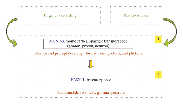
First, the calculations of transport for neutrons, protons, and hard X-rays are performed with the MCNPX code in order to determine the spatial and energy distributions of radiation fluxes [19]. Neutron, proton, and photon spectra are calculated in each volume with sufficient energy resolution so as to be used for the following calculations. For the protons, the prompt external doses are calculated from the radiation fluxes by using the ICRP-74 coefficients [35] and the data presented in Ref. [Reference Sato, Endo and Zankl36]. These results are representative of the doses delivered in the experimental hall in the case of the incidental presence of personal.
Second, by using the neutron, proton, and photon spectra calculated before, reaction rates for each material and type of particles are calculated separately. The inventory of all the produced radionuclei is performed using the Tendl2012 library. This allows deducing the spatial distribution of the produced radionuclei in various materials at different cooling times. This part of the calculation is performed with the code FISPACT-II [20]. The activation of the target is evaluated at this level.
The whole calculation sequence is shown in Figure 14.
Calculation sequence MCNPX + FISPACT (EASY II) used to determine the radiological inventory.
5.2. Prompt Doses
Immediate potential exposures have been evaluated for TS1 and TS2 experiments, for the photons, protons, and for the secondary neutrons (Figure 15). In our calculations, we assumed a chamber radius of 5 m (typical of installations like NIF or LMJ) made of 10 cm of aluminum and 40 cm of concrete. It is clear that the delivered dose close to the chamber wall depends on the inverse square of the radius. The total number of activated radionuclides, being integrated on the full-solid angle 4π instead, is independent of the chamber radius.
Polar graphs showing the prompt doses released following a 3.5 kJ shot on (a) a TS1 target maximizing X-ray bremsstrahlung emission (left: doses directly induced by photons; right: doses induced by photoinduced neutrons); (b) a TS2 target maximizing proton emission (left: doses directly induced by protons; right: doses induced by proton-induced neutrons). The arrow represents the direction of the laser beam (incident normally to the target surface). The inner circle represents a 5 m radius interaction chamber, while the most external circle represents the size of the whole experimental hall. The various features visible in this figure represent diagnostics and target inserters. These just represent a simple “case study” and do not necessarily refer to a concrete configuration of the interaction chamber and experimental hall during a real experiment.
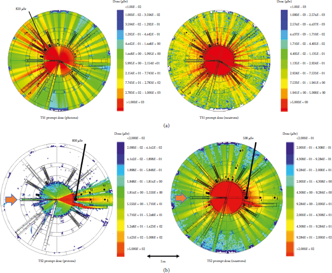
The photon and neutron induced prompt doses from a TS1 target are distributed rather homogeneously in the experimental hall. A dose of about 10 mSv, mainly due to photon, is calculated close to the chamber wall (@3.5 kJ).
The proton and neutron induced prompt doses from a TS2 target are quite lower. According to the TNSA process, a directional strong emission is observed in the direction normal to the target. A dose of about 1.5 mSv is predicted in the both directions (@3.5 kJ). Secondary neutrons contribute to 0.5 mSv of the total. It can be noticed that, in experiments with exceptionally good laser contrast, the emission of protons was symmetrically observed from the front and rear sides of a thin laser irradiated target (see, e.g., Ceccotti et al. [Reference Ceccotti, Lévy and Popescu37], where the contrast was better than 1010 and the laser intensity was 5 1018 W/cm2). This implies a prepulse intensity far below the threshold for plasma formation. In our case instead, the quite thick target and the presence of a preplasma (small but still significant) prevented observing such symmetrical emission.
In Figure 15, we did not evaluate the prompt doses directly related to the electrons escaping the targets. Such electrons will also be present and will propagate outwards the chamber wall and concrete shielding. However, it is well known that only a few electrons will be able to escape the targets (due to the induced charge separation) and will likely be unable to cross the target chamber wall (in the case of LMJ, this is made by 10 cm of aluminum+ 40 cm of concrete), therefore not contributing to the prompt dose outside the chamber. Indeed, they will generate bremsstrahlung X-rays in the chamber, but considering their low number their contribution will not be significant.
5.3. Equipment Characteristics
The radiological inventory strongly depends on the elements selected in modeling the installation, on their geometrical configuration, their distance from the interaction point (TCC: target chamber center), and on their composition. The inventory therefore requires to consider all the elements with a significant mass and/or located close to the source having a nonnegligible influence on the transport of particles and radiation.
In this study, to be a representative of the inserted devices and diagnostics, we considered the activation of an aluminum volume located at 10 cm from the target normal back side.
For a TS2 shot (worst case) with laser energy of 3.5 kJ, the specific activity of the aluminum achieves values above 700 Bq/g 10 min after the shot. The radionuclides, which contribute to most of such activities are 27Mg (half-life 9.5 min), 28Al (half-life 2.2 min), and 24Na (half-life 14.66 hours). However, the activation is decaying exponentially with time, and it reduces to the level of about 10 Bq/g three hours after the shot (main contributors being 24Na and 27Mg).
There is also a hazard of diagnostic contamination by the dispersion of the activated target and holder. Here, we have considered a target on an aluminum shaft and we assumed a target holder composed of 1 g of aluminum and 10 mg of glue for both types of targets. The real composition of the aluminum has been taken into account in the transport code (aluminum 5083 containing magnesium, manganese, etc.). Table 4 gives the total activity of the debris from TS1 and TS2 targets over time, and the radionuclides which contribute more.

6. Conclusion
This study presents the activation analysis induced by multipetawatt experiments at the energy level up to 3.5 kJ. The complete calculation sequence used in this paper includes the simulation of the interaction of the laser pulse with targets leading to energetic particle production. We modeled two types of experiments producing, respectively, mainly photons (TS1) or mainly protons (TS2). Calculations precisely take into account the transport of particles and radiation and the conversion of primary particles to secondary ones. This allows the estimation of the total activities within the interaction chamber and the experimental hall. In our calculations, whenever it was needed, we assumed a focal spot shape, a structure of the target and irradiation conditions, which would bring to overestimations of the expected levels of activation. This approach is indeed compatible with radiation safety procedures because it implies that the actual radiation doses are (slightly) less than what have we calculated.
Our simulation work shows that, in the laser energy and duration range considered here, the laser pulse duration only has a small influence on prompt doses and activation. In addition, a reduction in the focal spot size produces an increase in the intensity and leads to higher cutoff energies of electrons and protons. However, the total number of energetic particles with energies more than 1 MeV depends on the total laser energy and it remains approximately the same. Finally, we observed that induced prompt doses from TS1 targets are larger than those from TS2 targets. In the first case, the dose is distributed rather homogeneously in the experimental hall. Instead of TS2 targets, following the physics of proton emission due to the TNSA process, a directional strong emission is observed in two directions normal to the target.
Data Availability
The data are available from the corresponding author upon request.
Disclosure
The views and opinions expressed herein do not necessarily reflect those of the European Commission.
Conflicts of Interest
The authors declare that they have no conflicts of interest.
Acknowledgments
The authors acknowledge the financial support from the French National Research Agency (ANR) in the frame of “The investments for the future” Programme IdEx Bordeaux-LAPHIA (ANR-10-IDEX-03-02). This work has been carried out within the framework of the EUROfusion Consortium and has received funding from the Euratom Research and Training Program 2014–2018 under grant agreement no. 633053. This work was partly supported by the Aquitaine Regional Council. PIC simulations were calculated on the HPC resources of CINES under allocations 2012-056129, 2013-056129, 2014-056129, and 2015-056129 made by GENCI.


 Open access