


Introduction
The demand for energy is growing at a rapid rate due to increasing global population and the desire for a higher standard of living. Given finite terrestrial hydrocarbon natural resources (e.g., fossil fuels and biomass) and the impact of their consumption on climate change, it is critical for global sustainability that we use these resources as efficiently as possible. Unfortunately, the current efficiency of energy conversion from fossil fuels in the United States is just ∼36%, with the rest of the energy wasted as heat.1
In contrast, fuel cells directly convert fuel energy to electric power with significantly higher efficiency.Reference Minh2–Reference Wachsman, Marlowe and Lee6 Among the different types of fuel cells, the polymer-based proton exchange membrane fuel cells (PEMFCs) have been the most extensively studied, due in large part to their lower operating temperature (∼80°C), making them more amenable to portable and transportation (primarily automobile) applications, where rapid start-up from ambient temperature is desired. However, PEMFCs operate on pure H2 (with an extremely low CO content), requiring a H2 fueling infrastructure that does not currently exist. Moreover, considering the energy loss for H2 production from natural gas (the main source of H2 today), the “well to wheels” efficiency of PEMFCs is at best only ∼45%.
Solid-oxide fuel cells (SOFCs) use an oxygen-ion conducting electrolyte instead of a proton-conducting medium. They transport oxygen from the cathode (air electrode) to oxidize fuel at the anode (fuel electrode), thus providing the ability to directly use a variety of hydrocarbon fuels (Figure 1) with high fuel to electricity conversion efficiency (>55%, lower heating value [LHV]).3 Moreover, combined heat and power (CHP) applications, in which the waste heat is utilized, can exceed 85% efficiency,7 unmatched by any other energy conversion technology.
(a) Schematic diagram of a solid-oxide fuel cell (SOFC) with different magnifications from a stack cell to anode and cathode microstructures. (b) Commercially developed portable (250 W) and transportation (5 kW) SOFCs, and larger scale stationary (250 kW and MW) SOFCs planned for commercial demonstration. APU, auxiliary power unit. City gas refers to the domestic natural gas supply in Japan. Images of units were cited from web page of developer.

A typical SOFC consists of the electrolyte sandwiched between the anode and the cathode, with individual cells electrically connected in series by an interconnect to create an SOFC “stack” (Figure 1a).Reference Minh2–Reference Wachsman, Marlowe and Lee6 For the last three decades, Y2O3-stabilized ZrO2 (YSZ) has been the SOFC electrolyte of choice, as the best compromise between conductivity, stability, and cost.Reference Minh2–Reference Singhal and Kendall4 Due to YSZ’s limited conductivity, early SOFCs operated at ∼1000°C. These high temperatures result in high cell costs, long start-up and shut-down cycles, and unacceptable performance degradation rates due to reaction between component materials and electrode sintering.
Since then, operating temperatures for commercially developed SOFC stacks have been decreased to around 800°C. These so called intermediate temperature SOFCs (ITSOFCs) were achieved by the use of thin-film electrolytes and more active anode and cathode materials in tailored composite structures.Reference Wachsman and Lee8,Reference Brett, Atkinson, Brandon and Skinner9 These ITSOFCs are finding numerous applications on a variety of hydrocarbon fuels, as shown in Figure 1b.
However, a further decrease in operating temperature is still necessary to achieve a long service life (>10 years), as well as shorter time and lower energy start-up for transient and load-following applications.Reference Wachsman and Lee8,Reference Brett, Atkinson, Brandon and Skinner9 These low-temperature SOFCs (LT-SOFCs), operating at ≤650°C, require more conductive electrolytes and/or the ability to deposit thinner (near to submicron thickness) electrolytes to reduce the ohmic I–R losses. In addition, they require significant composition and nano-/microstructural advances to reduce non-ohmic cathode and anode polarization losses. The articles in this issue summarize progress and challenges for the development of LT-SOFCs, from materials, to cell designs, and to new analytical techniques.
Lowering the electrolyte resistance
The first step to achieving high power densities at low temperatures is reduction of the electrolyte ohmic I–R loss. This can be accomplished by making the electrolyte thinner and/or developing higher conductivity materials. The first approach, as applied to YSZ, was a major innovation in the development of ITSOFCs, transitioning from thick (∼150 μm) self-supported electrolytes to thin (∼10 μm) electrode supported electrolytes. For example, electrochemical vapor deposition (EVD) was pioneered by Westinghouse to prepare YSZ thin-film electrolytes on porous cathode supports around 1990.Reference Singhal and Kendall4 However, because of the high cost and environmental impact of the chloride reactants involved, the EVD method is not commonly used at present. Instead, more conventional wet processing techniques, such as slurry or colloid coating by spin and spray methods, or even screen printing and tape casting/calendering methods, are widely used by the SOFC industry due to their inexpensive processing costs.
In a conventional SOFC,Reference Minh2,3 a porous metal-oxide composite (“cermet”) is generally used as the anode support layer. This is typically formed, for instance, from a ∼50:50 volumetric ratio of NiO to YSZ. Upon subsequent high-temperature exposure to the anode gas, NiO is reduced to Ni, creating the metallic conducting and catalytic phase, as well as opening up porosity by the NiO to Ni volume contraction. A dense electrolyte film is then deposited on the anode support using one of the previously mentioned methods. These conventional processes require a subsequent high-temperature co-sintering step, and for some materials, this necessitates a buffer layer to suppress reaction between the electrode and electrolyte.
Further reduction to ∼1-μm-thick electrolytes to achieve LT-SOFCs is described by Prinz et al. In this microelectromechanical systems (MEMS)-based approach, thinner electrolyte films are deposited on a dense substrate, which is subsequently rendered porous.Reference Su, Chan, Shim, Fasching and Prinz10–Reference Evans, Bieberle-Hutter, Rupp and Gauckler12 A typical example is ∼100 nm YSZ deposition on a Si substrate followed by chemical etching of the Si to make it porous. These techniques are particularly important for so-called “micro-SOFCs,”Reference Evans, Bieberle-Hutter, Rupp and Gauckler12 which are envisioned more for battery replacement than large-scale power generation.
The other approach, increasing the intrinsic electrolyte conductivity, is a fundamental area of research in materials science that has been applied primarily to materials with fluorite and perovskite structures. Figure 2 shows a comparison of the ionic conductivity for several potential SOFC electrolytes.
Comparison of ionic conductivity of various solid oxide electrolytes. Note: ESB, Er0.4Bi1.6O3; DWSB, Dy0.08W0.04Bi0.88O1.56; GDC, Gd0.1Ce0.9O1.95; SNDC, Sm0.075Nd0.075Ce0.85O2; YSZ, Y0.16Zr0.84O1.92; LSGM, La0.8Sr0.2Ga0.8Mg0.2O3; LSGMC, La0.8Sr0.2Ga0.8Mg0.115Co0.085O3; BCY, BaCe0.92Y0.08O3.
The fluorites include zirconia, such as YSZ, as well as ceria and bismuth oxide-based electrolytes that conduct via an oxygen vacancy ( ${\rm{V}}_{\rm{o}}^{..} $) mechanism. The ${\rm{V}}_{\rm{o}}^{..} $ are created in ZrO2 and CeO2 by substituting a lower valent cation on the M4+ cation site, whereas for Bi2O3, 25% of the anion sites are intrinsically vacant because Bi has a valence of 3+. The issue with increasing fluorite conductivity is increasing ${\rm{V}}_{\rm{o}}^{..} $ concentration without ordering the anion sublattice, which would decrease anion mobility.Reference Wachsman13 This can be accomplished by using highly polarizable dopants with radii close to that of the host cationReference Boyapati, Wachsman and Jiang14 and randomizing the site energetics by multi-cation doping, as shown by the increase in conductivity of Dy2O3 and WO3 co-stabilized Bi2O3 (DWSB),Reference Jung, Duncan and Wachsman15 relative to Er2O3 stabilized Bi2O3 (ESB), and Sm2O3 and Nd2O3 co-doped CeO2 (SNDC)Reference Omar, Wachsman and Nino16 relative to Gd2O3 doped CeO2 (GDC).
Although extremely high conductivity has been achieved in these materials, they have thermodynamic stability issues under the reducing atmosphere at the anode. Partial n-type electronic conductivity, decreasing the open-circuit potential (OCP) and thus efficiency, occurs for CeO2,Reference Steele17 and Bi2O3 can decompose to metallic Bi.Reference Wachsman, Ball, Jiang and Stevenson18 In order to use these high conductivity electrolytes, Wachsman developed a bilayer electrolyte consisting of ESB on the air-cathode side and GDC on the fuel-anode side (Figure 3a).Reference Wachsman and Lee8,Reference Ahn, Pergolesi, Camaratta, Yoon, Lee, Lee, Jung, Traversa and Wachsman19,Reference Lee, Yoon and Wachsman20 Since the partial electronic conduction in CeO2 is blocked by the Bi2O3 layer, SOFCs with this bilayer electrolyte show close to theoretical OCP (Figure 3c) and a high power density (2 W cm–2) at 650°C (Figure 3b). This power density translates to ∼3 kW kg–1 at the stack level, exceeding the power density of internal combustion engines and demonstrating the feasibility of LT-SOFCs for transportation applications.Reference Wachsman and Lee8 Moreover, this approach provides for even further increases in power density or reduction in temperature by using the more conductive DWSB/SNDC bilayer electrolyte (Figure 3b).Reference Wachsman and Lee8
(a) Schematic of a solid-oxide fuel cell (SOFC) concept with a bilayer of Er2O3 stabilized Bi2O3 (ESB) and Gd2O3 doped CeO2 (GDC), demonstrating the effect of relative layer thickness on interfacial oxygen partial pressure ( ${\rm{V}}_{\rm{o}}^{..} $) and ESB stability. L ESB, ESB layer thickness, L GDC, GDC layer thickness, τoptimal, optimal thickness ratio. (b) Current-voltage behavior (left y-axis) and power density (right y-axis) for SOFCs with (GDC) single-layer (solid-blue line) and ESB/GDC bilayer (solid-red line) electrolytes at 650°C using 90 sccm of 3% wet H2 (anode side)/dry air (cathode side). With the ESB/GDC bilayer electrolyte, a power density of ∼2 W cm–2 at 650°C was achieved due to higher open-circuit potential (OCP) and reduced cathodic polarization. Assuming higher OCP (∼1 V) by controlling total thickness and thickness ratio of a more conductive Dy2O3 and WO3 co-stabilized Bi2O3/Sm2O3 and Nd2O3 co-doped CeO2 (DWSB/SNDC) bilayer electrolyte, the projected maximum power density (dotted-red lines) is ∼3.5 W cm–2 under the same conditions. (c) Effect of total thickness and thickness ratio of bilayered electrolyte on OCP. OCP increases as the total thickness and ESB/GDC thickness ratio increases and as temperature decreases, indicating the potential to achieve theoretical OCP at these temperatures.Reference Wachsman and Lee8
A number of perovskites have also been investigated as potential high conductivity electrolytes. While most of them had appreciable p-type conduction, resulting in reduced OCP and thus SOFC efficiency, IshiharaReference Ishihara, Matsuda and Takita21 and GoodenoughReference Huang, Tichy and Goodenough22 discovered LaGaO3-based electrolytes (Figure 2) with high  ${\rm{V}}_{\rm{o}}^{..} $ conduction, negligible electronic conduction, and, like YSZ, thermodynamic stability in the anode gas environment (La0.8Sr0.2Ga0.8Mg0.2O3 [LSGM] shows pure oxide ion conductivity from oxygen partial pressures, P O2 = 1 atm to 10–21 atm). Significant improvements in their conductivity and use in SOFCs ensued. For example, Ju et al. prepared 5-μm-thick LSGM films by pulsed laser depositionReference Ju, Eto, Inagaki, Ida and Ishihara23,Reference Ju, Ida and Ishihara24 and demonstrated SOFCs that use a LSGM (5 μm)/Sm-doped CeO2 (400 nm) double layer electrolyte.Reference Ju, Eto, Inagaki, Ida and Ishihara23 The SDC interlayer is used as a buffer layer to prevent Ni diffusion from the substrate to the LSGM electrolyte. As shown in Figure 4, the cell achieves a reasonably large power density (0.5 W/cm–2) at only 500°C.
Power generation (filled markers) and voltage (open markers) curves of the cell using a La0.9Sr0.1Ga0.8Mg0.2O3/ Sm0.2Ce0.8O2 bilayer electrode. Ni-Fe anode substrate and Sm0.5Sr0.5CoO3 cathode and humidified hydrogen and oxygen were used as the fuel and oxidant, respectively.Reference Ju, Eto, Inagaki, Ida and Ishihara23
In the search for high conductivity perovskites, a number of other oxide electrolytes were found that had the desired properties of stability to reduce gas, negligible electronic conductivity, and high ionic conductivity, such as Y2O3-doped BaCeO3 (BCY) (Figure 2).Reference Ma, Shimura and Iwahara25 However, ionic conductivity is primarily protonic (or mixed proton and oxygen-ion under certain conditions). Technically, the resulting fuel cell is a SOFC since it uses a solid-oxide electrolyte, even if it is a proton conductor rather than an oxygen-ion conductor, and the article by Fabbri et al. in this issue describes these materials and their potential benefits.
Protons have the smallest ionic radii, and so a high mobility is expected, and a high ionic conductivity can be obtained for materials with substantial proton concentrations. As such, there are numerous recent advances in other inorganic proton-conducting materials for lower temperature fuel cells.Reference Heo, Shibata, Nagao, Hibino and Sano26–Reference Hibino, Shen, Nishida and Nagao30
Increasing cathode catalytic activity and conductance
Cathode and anode electrocatalytic reactions are thermally activated, and thus their rates decrease with decreasing operating temperature, resulting in large electrode overpotentials for LT-SOFC operation.Reference Wachsman and Lee8 This is even more important for the oxygen reduction reaction (ORR) at the cathode, since the activation energy for oxygen dissociation is large. In contrast, fuel oxidation at the anode is less temperature dependent.
Therefore, with low resistance electrolytes, the overall cell performance is determined by the cathodic reaction at temperatures lower than 500°C.Reference Wachsman and Lee8 The cathodic ORR is expressed as follows:
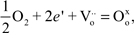 $${1 \over 2}{\rm{O}}_{\rm{2}} |\,\,\,2e'\,\,\,|\,{\rm{V}}_{\rm{o}}^{..} = {\rm{O}}_{\rm{o}}^{\rm{x}} $$,
where, in (Kröger–Vink) solid-state nomenclature, e' is an electron and  ${\rm{O}}_{\rm{o}}^{\rm{x}}$ is an oxygen on an oxygen-lattice site. For typical electronic conducting cathode materials such as LSM, the ORR occurs at the triple-phase boundary (TPB) (i.e., gas–electrolyte–electrode), as schematically shown in Figure 1a, requiring an extended porous composite cathode structure for gas, ion, and electron transport. However, with the advent of mixed ionic electronic conductors (MIECs), such as LSCF, ${\rm{V}}_{\rm{o}}^{..} $ can diffuse in the MIEC bulk, resulting in extended reaction sites from the TPB to the two-phase boundary (gas–electrode surface).
Numerous Ln1–xSrxMO3 (M = Mn, Fe, Co) perovskite oxides have been used for SOFC cathodes. La0.6Sr0.4Co0.2Fe0.8O3 is widely used for ITSOFCs due to its high electronic and ionic conductivity, high ORR activity, and relatively high stability.Reference Minh2–Reference Singhal and Kendall4 Among these, Ba0.5Sr0.5Co0.8Fe0.2O3 (BSCF) is reported to have the lowest area-specific resistance due to its higher ORR activity and oxygen-ion diffusivity.Reference Shao and Haile31 Because of insufficient stability, BSCF cathodes exhibit rather large degradation rates. In contrast, Sm0.6Sr0.4CoO3 shows reasonably high stability and surface activity.Reference Ishihara, Honda, Shibayama, Minami, Nishiguchi and Takita32 Recently, many new materials have been reported that show high activity and stability, such as perovskite and double perovskite-related compounds, GdBaCo2O5,Reference Chang, Skinner and Kilner33 or composite oxides such as Ba0.6La0.4CoO3-Pr2Ni0.71Cu0.24Ga0.05O4.Reference Xie, Ju, Matsuka, Ida and Ishihara34 It is also reported that the layered interface of LaCoO3/La2CoO4 shows extremely high activity to oxygen dissociation.Reference Sase, Yashiro, Sato, Mizusaki, Kawada, Sakai, Yamaji, Horita and Yokokawa35,Reference Kubicek, Cai, Ma, Yildiz, Hutter and Fleig36
To gain a fundamental understanding of the ORR mechanism on these materials, several techniques are being used, such as conductivity relaxationReference Wang, van der Heide, Chavez, Jacobson and Adler37 and in situ Reference Armstrong, Duncan and Wachsman38 and ex situ Reference Carter, Selcuk, Chater, Kajda, Kilner and Steele39 oxygen–isotope exchange. These, combined with computational materials insightsReference Kuklja, Kotomin, Merkle, Mastrikov and Maier40 and quantification of the cathode microstructure using 3D focused ion beam techniques,Reference Gostovic, Smith, Jones and Wachsman41–Reference Wilson, Duong, Gameiro, Chen, Thornton, Mumm and Barnett43 are expected to provide a path forward to rational design of LT-SOFC cathodes.
While new materials and structures continue to be developed, cathodic overpotential remains the major impediment to LT-SOFCs. However, as SOFC temperatures are lowered, nano-featured electrode structures become more stable, as sintering and reactivity between components are decreased, and thus may provide the solution due to their higher specific surface area, as described by Lee and Wachsman in this issue.
Increasing anode fuel tolerance and thermal cyclability
For PEMFCs, Pt is the most active and widely used anode catalyst. However, the use of Pt causes obvious cost issues. In contrast, Ni is the most widely used catalyst for SOFCs and ITSOFCs in the form of Ni-YSZ cermet anodes.Reference Minh2–Reference Singhal and Kendall4 With decreasing operating temperature, the surface activity of Ni for electrochemical fuel oxidation, as well as coking (carbon deposition) and sulfur tolerance, becomes insufficient. Therefore, various additives to enhance the activity of Ni are also being investigated. Among these additives, it has been reported that a small amount of Fe added to Ni can increase the activity toward the anode reaction because alloying with Fe stabilizes the fine particle size of Ni, avoiding coarsening of the electrocatalyst and an associated decrease in surface area.Reference Ishihara, Yan, Shinagawa and Matsumoto44 Mixing CeO2-based oxides with Ni also yields highly active anodes due to the rather unique high activity of doped CeO2 (relative to YSZ) itself for the anodic reaction.Reference Huang and Huang45–Reference Zhen, Tok, Jiang and Boey47 Therefore, Ni-GDC cermet anodes are suitable for maintaining small overpotentials in the ITSOFC range.
Achieving low anodic overpotentials at lower temperatures calls for alternative anode materials. Moreover, the current use of Ni also limits the ability to thermally cycle to room temperature, since thermodynamically it will form NiO even under reducing gas environments at low temperatures, and the corresponding Ni/NiO volume change will cause cell cracking. Unfortunately, aside from oxide anodes, which still show much larger anodic overpotentials than the Ni baseline, there are currently few other candidate materials. In this respect, a new concept for active anodes could prove a welcome leap forward for LT-SOFC technology with fuel flexibility.
Commercialization of fuel cells and requirements for lowering operation temperature of SOFCs
As shown in Figure 1b, there is a wide range of SOFC applications ranging in size from watts to megawatts. These larger size SOFC units mainly use high-temperature (>800°C) SOFCs. Among the US companies providing large power size units, Bloom Energy has the greatest number of installed units, and their “Energy Server,” which is offered in capacities of 100 or 200 kW, has already sold more than 200 units.48 These units operate at around 950°C and have a reported conversion efficiency higher than 50% LHV to AC power in a modular configuration. There are several other SOFC manufacturers in the United States, ranging from Adaptive Materials for portable power and Delphi for transportation auxiliary power units, to Fuel Cell Energy and LG Fuel Cell Systems for large-scale stationary distributed generation. A recent newcomer, Redox Power Systems, is focused on commercializing the bismuth-oxide/ceria bilayer electrolyte LT-SOFC technology shown in Figure 3.
Among European manufacturers, Topsoe Fuel Cell is developing a unit called PowerCore, for micro CHP at 1–1.5 kW (DC). The operating temperature is closer to 750°C, and they claim 64% direct current efficiency (LHV) by anode gas recycling. The system unit contains 75 planar cells in the stack and the hot balance of plant components for fuel and air processing. The volume of the unit is 38 L and has a weight of 33 kg.
The Ceres Power Steel Cell, a “kW class” metal supported technology, operates in the 500–610°C temperature range. These have been run as short stacks of a few cells for >10,000 h and report degradation rates of <0.5–0.24%/kh. The metal supported technology gives excellent cycling performance, including over 600 rapid thermal cycles over 2000 h, showing a loss of less than 4% in performance.
In Japan, there has been a tremendous increase in residential fuel cells, with over 33,500 sold since 2009 (Figure 5a).48 Initially, around 5000 units per year were sold, but now more than 20,000 units are being sold annually due to increased domestic energy costs. These units are CHP systems for residential applications, with the majority being PEMFC based. Recently, commercial residential CHP systems based on SOFC technology and using natural gas have also become available.49 The electric power output of these residential CHP systems is ∼1 kW, with co-production of hot water. Since heat and power account for 30% and 40%, respectively, of energy consumption in the home, such simultaneous heat and electrical power generation with high efficiency affords a significant reduction in home energy consumption.
(a) Number of fuel cell units of all types sold in Japan since 2009, broken down by year and fuel type. LP gas, liquefied petroleum gas; city gas is the domestic natural gas in Japan. (b) Comparison of lower heating value (LHV) energy conversion efficiency for the three types of combined heat and power systems presently available (i.e., gas engine, proton exchange membrane fuel cell [PEMFC], and solid-oxide fuel cell [SOFC]). Data is cited from http://www.ace.or.jp/web/works/works_0090.html.
Figure 5b shows a comparison of energy conversion efficiency for three types of domestic CHP systems presently available: gas engine (82%), PEMFC (85%), and SOFC (90%). CHP systems using gas engines generate more heat than electricity, while CHP systems using PEMFC technology generate heat and electrical power almost equally. In contrast, SOFC-based systems have both the highest electrical efficiency, generating electricity with around 46.5% efficiency, and the highest overall efficiency, since the 43.5% energy converted to heat can be more effectively utilized due to its higher quality (higher temperature).49 Since the demand for electricity is higher, a CHP system using a SOFC is more attractive for residential CHP systems.
Since current SOFCs operate at ∼700°C, the system must operate 24 hours a day. This means that the SOFC is running under partial load conditions at night, which significantly decreases its energy conversion efficiency. Although the energy conversion efficiencies of current SOFCs are reasonably high under optimized operating conditions (∼50% LHV for ac power),50 they decrease with decreasing power density due to the extra energy required to maintain operating temperature under partial load conditions. In this regard, decreasing the operating temperature will allow higher conversion efficiencies to be maintained even under partial load conditions.
For these considerations, LT-SOFCs are anticipated to provide higher energy conversion efficiency under partial load condition. In addition, performance degradation is the most important concern, as discussed further in the article by Druce et al. However, considering the high conversion efficiency from chemical energy to electric power, the market for SOFC power generation systems is expected to increase significantly.
In this issue
The five articles in this issue expand upon the LT-SOFC technical overview presented. Lee and Wachsman demonstrate the importance of nanostructure control for SOFC materials, in particular, how the electrode properties can be improved by controlling the structure and morphology at the nanoscale.
Fabbri et al. discuss the application of proton-conducting oxide materials for LT-SOFCs. Although the power densities currently produced using proton-conducting oxides are not high compared to those of oxide ion conductor-based SOFCs, their high conductivities at low temperatures hold great potential for future LT-SOFC development.
An et al. present applications of Si-based semiconductor MEMS technology for preparation of micro-SOFCs. These small thin-film electrolyte supported SOFCs show reasonably high power densities at decreased operating temperatures.
Suzuki et al. scale this up a notch to 1-mm-diameter microtubular SOFCs, fabricated using simple extrusion and dip-coating techniques. These microtubular SOFCs are excellent candidates for small power sources demonstrating reasonably high power densities in the 450–550°C range.
Finally, Druce et al. discuss the links between surface segregation of SOFC materials and SOFC performance degradation. Field tests point to the need to improve the stability of SOFC power generation. In addition, it has recently become clear that surface segregation of Sr or La to the surface of perovskite oxide-based cathodes occurs rapidly during the initial start-up period, suggesting the possibility that the surface activity of such perovskite-based cathodes could be further improved by adopting appropriate doping strategies.
Concluding remarks
SOFCs have tremendous potential to increase the efficiency of hydrocarbon fuel use, thus decreasing greenhouse gas emissions from hydrocarbon fuels, which is our current predominant energy resource. While they are already being commercialized, there are still many issues to overcome. The most significant drawbacks at present are cost and degradation. By decreasing the cell operating temperature, less expensive materials can be used, and performance degradation will be suppressed. Furthermore, energy conversion efficiency will be improved, due to the increased efficiency under partial load conditions and the ability to operate under transient conditions. In addition, SOFCs with lower operating temperatures will enable applications in new areas, such as sources of electrical power for mobile devices, for which micro-SOFCs would be particularly well suited. The development of low-temperature SOFCs is of great interest to complement existing intermediate temperature SOFC technologies for power generation applications.
We hope that each article in this issue of MRS Bulletin will inspire new researchers to join this exciting field and accelerate the development of LT-SOFCs. While recent fundamental scientific research and technological developments have significantly advanced the field, further new concepts and innovative materials are needed to enable LT-SOFCs to help deliver a lower carbon energy society in the future.


