


Introduction
Worldwide approximately 430 million people suffer a disabling hearing loss (>35 dB).1 Conductive hearing loss is a category of hearing losses and accounts for roughly 5–10 per cent of worldwide hearing loss cases.Reference Hampton, Loureiro, Mortimer and Nyirenda2 It is estimated that 80 per cent of global hearing loss is situated in low- and middle-income countries (LMICs).1 In Nepal, chronic otitis media is particularly prevalent and represents the leading cause of hearing loss in children. In a cross-sectional study of 79,340 Nepalese schoolchildren, the prevalence of hearing impairment was 5.73 per cent, and of those children with hearing loss, 70.47 per cent had conductive hearing loss.Reference Maharjan, Phuyal and Shrestha3 Conductive hearing loss results from impaired sound transmission from the external auditory canal to the oval window in the middle ear. There are many potential causes for this ranging from simple obstruction by ear wax, through accumulation of fluid in the middle ear, as in the common affliction of childhood, middle ear effusion, to more serious issues such as damage to the tympanic membrane and ossicular chain. Impaired sound transmission as a result of degraded, failed or immobile ossicular chain can result from cholesteatoma, chronic otitis media, congenital malformations, otosclerosis or traumatic disruption of the ossicular chain.Reference Andersen, Jepsen and Ratjen4
In many cases of chronic otitis media (COM), the tympanic membrane will need reconstruction (tympanoplasty). In many cases, the ossicular chain is also damaged by the infective process, and sometimes it has to be removed during surgical disease clearance. Repair of the conductive system is known as ossiculoplasty and is often undertaken as part of tympanoplasty or other middle ear and mastoid surgical procedures. In some cases, autologous repair materials (including residual ossicle or cortical bone grafts) are unsuitable, and an artificial partial ossicular replacement prosthesis (PORP) can bridge the gap between drum and stapes superstructure. However, in many cases, usually when the stapes arch is absent and footplate mobile, then a device is needed to transmit sound from the tympanic membrane to the footplate of the stapes. In such cases, a total ossicular replacement prosthesis (TORP) is required.Reference Yu, He, Ni, Wang, Lu and Li5 In such cases, repair with autologous ossicle or bone is technically challenging and prone to failure, hence artificial prostheses are preferred. Various commercial TORPs are available and commonly consist of a footplate that is to be placed on the stapes, a head that is to connect with the tympanic membrane and an adjustable shaft that connects head and footplate. Titanium is the most commonly used material for TORPs and shows high success rates and low extrusion rates.Reference Jung, Yoo and Lee6–Reference Canzi, Carlotto, Bruschini, Minervini, Mosconi and Caliogna8 Other materials used are ceramics, or polymers can make the TORP more affordable. However, these other materials have drawbacks in lower success rates, higher extrusion rates or lower adaptability.Reference Jung, Yoo and Lee6
In LMICs, TORPs are often not available and are too expensive for most of the population. In our hospital, a TORP hand made from titanium dental wire (0.3 or 0.5mm diameter) has been used successfully for many years. The production and quality depended highly on the expertise of a single surgeon. The surgical team felt this idea could be further improved to produce more consistently shaped TORPs, with less potentially sharp edges, depending less on the manufacturing skill of a single surgeon. Therefore, the aim of this project was to develop and validate an open-source design of an improved titanium TORP that can either be easily obtained or locally produced in LMICs in small quantities, just to suffice for a hospital’s need. This paper presents the final design, the engineering tests done and results of ex-vivo tests with ENT surgeons.
Methods
Design requirements
Design requirements were gathered using literature, commercially available information and through discussions with the surgical team. These requirements were documented extensively in the work of Ten HaveReference ten Have9 and Hou.Reference Hou10 Key requirements are summarised here: (1) The prosthesis should fit middle ear anatomy, requiring foot to head lengths between 3 and 6 mm. (2) The foot of the prosthesis should fit the space available on the stapes and be less than 1 mm in size. (3) The head of the TORP should be 3 mm to fit under the tympanic membrane. (4) The prosthesis should have no sharp edges or burrs. (5) The material should be medical grade titanium for biocompatibility, acoustic properties and long-term stability. (6) Prosthesis cost should be low, aiming at a maximum of USD 10. (7) The sound transmission transfer function should be close to a commercial prosthesis (ALTO Dornhoffer, Grace Medical). (8) The sound transmission transfer function should be close to a commercial prosthesis (examples used: ALTO Dornhoffer, Grace Medical; or mXACT Total Prosthesis Offcenter, MED-EL Medical Electronics, Innsbruck, Austria) for the 0.1 to 4 kHz range. (9) For adjusting to patient-specific anatomy, the prosthesis should allow peri-operative adjustment. (10) Any pre-/peri-operative preparation for using a TORP should take surgeons less than 10 minutes. (11) Handling of the prosthesis during placement should be easy. (12) The design should allow good visibility of the surgical field during placement.
Design
Through brainstorming and literature review, various different manufacturing processes were defined. These were assessed on affordability, precision, physical/mechanical properties and simplicity. Two manufacturing directions were selected as promising approaches for the TORP design: a shape optimised for titanium 3D printing (the 3DP-T design); and laser cutting from thin titanium sheet metal and subsequent forming using low-cost 3D printed plastic forming tools (the SM-T design). Different TORP concepts were designed for both manufacturing approaches, and a final concept was decided for each manufacturing approach.
The 3DP-T concept consisted of a small circular base, a straight stem and a large, open circular head that connects to the stem in the centre (Figure 1). The small circular base fits into the stapes space (in oval window niche and onto stapes footplate), the large head allows connecting to the tympanic membrane whilst the open structure allows good visibility of the surgical site. The stem length can be altered in the 3D design file to generate prostheses with variable lengths. The design was printed on a Selective Laser Melting (SLM) machine, using Ti6A14V medical grade titanium powder. Support structures had to be added to stabilise the print. This support material had to be manually removed after printing and the 3DP-T surface had to be improved using sandpaper.
Impression of the 3DP-T design, as CAD model.

Figure 1 Long description
The image shows a CAD model of a prosthetic design. It consists of a small circular base at the bottom, a straight stem extending upwards and a large open circular head at the top. The head is connected to the stem at the center, forming a T-shape. The design allows for visibility of the surgical site and can be adjusted in length through the 3D design file. The model is intended for fitting into specific anatomical spaces, such as the stapes space and tympanic membrane.
The SM-T concept consisted of a small semi-circular base, a large almost circular head and a long thin stem connecting the centres of both features (Figure 2). The small base fits into the stapes space, the large head allows connecting to the tympanic membrane and the long stem connects both ends, with the stem length adjustable to fit different ear geometries. The open structure allows a good view during surgery. This shape is cut from 0.25 to 0.3 mm thickness titanium grade 2 sheet metal using a precision laser cutter and using the computer-aided design (CAD) files.Reference Knulst, van Asperen, Gautam, Geerts, ten Have and Hou11 During cutting, the stem of the SM-T is in the direction of the grain of the titanium sheet for good bending performance. After cutting, the edges are post-processed mechanically to leave no burrs or sharp edges. To adjust the length of the SM-T for different ear anatomies, the long stem is bent in a zig-zag shape to reduce its length to 3 mm. (The alternative would be to cut multiple TORPS of fixed lengths with straight stems.) The zig-zag method allows using a single-size sheet metal part for more economic manufacturing, less wastage and adjustability during surgery.
Impression of the SM-T design, as CAD model.

Figure 2 Long description
The image shows a computer-aided design model of a metal component. It features a semi-circular base connected to a curved stem that extends upwards in a zig-zag pattern. The design appears to be cut from sheet metal, showcasing a smooth and precise structure. The component's open design allows visibility through its structure, indicating potential use in applications requiring clear access or view during operation.
After cutting, the sheet metal shape has to be formed into the desired shape. For this, two different 3D printed rolling pin moulds were made using 3D CAD models,Reference Knulst, van Asperen, Gautam, Geerts, ten Have and Hou11 one for small SM-Ts (3 to 4 mm range, using a 0.8 mm metal pin) and one for bigger SM-Ts (4.5 to 6 mm range, using a 1.2 mm metal pin). The rolling pin moulds produce the smallest size SM-T for each range (3 or 4.5 mm depending on the mould used) that then can be extended to the desired length by using extension blocks, available in different sizes.Reference Knulst, van Asperen, Gautam, Geerts, ten Have and Hou11 These 3D printed extension blocks were printed on a Prusa iMK3s printer, using PETG filament (dried for improved accuracy), using several custom settings for increased accuracy: 0.05 mm “layer height”, 0.0005 “slice gap closing radius” and enable “avoid crossing perimeters”. Extension blocks are made from 3.0 to 6.0 mm height, in steps of 0.5 mm.
Forming consists of three main steps for which step by step detailed descriptions can be foundReference Knulst, van Asperen, Gautam, Geerts, ten Have and Hou11: (1) Use pliers to grip the footplate near the edge and then fold the SM-T over the pliers tip. (2) Position the SM-T in a 3D printed plastic mould with a metal pin, then rotate the plastic part around the metal pin for 180 degrees. (3) Place the formed SM-T in a 3D printed extender block of the appropriate size to extend to the exact desired length.
The result is a SM-T with a sharply bent footplate, followed by a straight neck perpendicular to the footplate and then an angled section towards the edge of the head plate. Some manual fine adjustments can then be done to optimise the SM-T shape. This can also be done peri-operatively to adjust to patient specific characteristics.
Tests/validations
Different tests were developed to test the prototypes and manufacturing methods on various aspects of the design.
Prototype dimensional assessment
Both 3DP-T and SM-T prototypes were measured on dimensional accuracy of the produced parts using a measuring microscope (MF-U, Mitutoyo, Japan). The relative error between designed and realised dimensions of the head, the foot and the total length were measured and expressed as an error percentage. TORP mass was measured using a precision scale (AE50, Mettler Toledo, Switzerland). For comparability only the 4.5 mm length TORP was used.
The reproducibility of the bending process for the adjustable SM-T design was validated through a test done by the lead researcher. An SM-T was bent into the desired shape using the recommended bending method, and the geometry obtained was compared to the intended geometry. A 3.0, 4.5 and 6.0 mm length SM-T was bent into shape three times. The resulting height of the SM-T, the width, the length of the footplate and the footplate to shaft distance were measured (Figure 3).
Definition of measuring the dimensions of a formed SM-T.

Figure 3 Long description
The image shows a bent object with several measurements labeled. The top horizontal section is marked as 3.403 millimeters. The vertical section on the left is labeled as 4.478 millimeters. The curved section in the middle is marked as 1.627 millimeters. The bottom horizontal section is labeled as 1.038 millimeters. The object appears to be positioned against a textured background.
As there was a surgical training happening coincidentally, the SM-Ts could be tested if they fit in cadaver ears. All three participating ENT surgeons had opportunity to fit an SM-T into a cadaver ear and give their feedback.
Sound transmission transfer function measurement
To measure the transfer function of the devices, a mechanical middle ear model (MMM) was developed as described earlier.Reference ten Have9, Reference Hou10, Reference Meister, Walger, Mickenhagen, Von Wedel and Stennert12 The setup (Figure 4) consisted of a speaker, a 3D printed plastic cone with a microphone, a holder for the prosthesis, a movable tube on a linear stage (PT1-M, Thorlabs, Newton, USA) and a Laser Doppler Vibrometer (LDV) (PSV-400, Polytec GmbH, Baden-Württemberg, Germany). The prosthesis was placed between two silicon membranes (shore 8A, 15x15mm, 0.3 mm thick), the prosthesis head touching Membrane 1 and the footplate Membrane 2. The linear stage was used to apply a fixed pre-tension by moving Membrane 2 exactly 0.5 mm inwards to keep the prosthesis in place. The speaker was used to produce a computer-generated periodic chirp signal containing frequencies from 0.1 to 10 kHz at 5V amplitude to include all relevant frequencies. The microphone recorded the sound near Membrane 1. The LDV was aimed at Membrane 2 to record the vibrations transferred from Membrane 1 to Membrane 2 through the prosthesis. The transfer function (TF) of the empty setup (no prosthesis) was determined using the recorded data of the microphone and the LDV. The TF of the prosthesis was determined by subtracting the TF of the empty setup from a measured TF with a prosthesis in place. The sound transmission TF was measured three times for each prosthesis and averaged into one TF. Next, the root mean square error (RMSE) between the TF of a certain prosthesis and the TF of the empty setup was calculated across a certain frequency range. This RMSE represents the improvement in sound transmission across the frequency range. Finally, the difference in RMSE value of each prosthesis with the ALTO commercial prosthesis was calculated, as a percentage of the ALTO RMSE. This allows to compare sound transmission of the different prostheses to one fixed, but arbitrary reference.
Schematic of the MMM, depicting the key components (left). The actual components of the MMM test setup (right).

Figure 4 Long description
The image shows two parts: a schematic diagram and a setup illustration of a mechanical middle ear model. The schematic on the left includes a laser vibrometer, labeled as 'Laser Vibrometer', connected to a system with components labeled M2, TCRP, M1 and a microphone. A speaker is shown producing sound pressure. The right side depicts the actual setup with labeled components: a movable tube, membrane holder, linear actuator, microphone, breadboard and speaker. The setup is arranged on a platform with a detailed view of each component's position and function.
Bending material fatigue testing
Bending metals in sharp angles can cause permanent change to the base material that result in material damage. As surgeons might correct an SM-T before or during surgery, it is relevant to know if adjustments can be safely done. Therefore, a test was done in which the researcher repeatedly bent and unbent 13 SM-Ts, with material condition checks after each cycle, to establish a safe maximum of sharp re-bends. A digital microscope (Toolcraft UM012B) was used to inspect the samples under magnification (magnification varied between 10× and 20×). Notes were made whether any sign of damage could be seen, looking at the following failure modes: flattening, irreversible warp, visible cracks and dark surface spots or a complete structural failure/breakage. The number of bend re-bend cycles at which the failure mode was first observed was noted for each failure mode separately.
Learning curve for reliable SM-T forming by surgeons
To assess the feasibility of production of the SM-T by surgeons, a training session was organised to teach bending the SM-T from sheet metal using a printed guideline with visuals and with a bending expert (lead researcher) for instruction and coaching. Three experienced ENT surgeons participated. Surgeon 1 bent seven short shaft SM-Ts, Surgeon 2 bent seven long shaft SM-Ts and Surgeon 3 bent four short and four long shaft SM-Ts. The geometry of the bent SM-Ts were assessed by a single researcher using images made with a calibrated digital microscope made from three orthogonal views (front, side and top view). Quantitative errors were calculated for the footplate and headplate dimensions, the head-to-footplate length and any frontal or lateral offset angles. In addition, several qualitative aspects were scored as binary parameters, including headplate and footplate parallelism, headplate flatness, bend shape and neck straightness. Continuous parameters received interpolated penalties proportional to the magnitude of deviation, while binary parameters incurred fixed penalties when deviations were present. All penalties were summed to obtain a total score per SM-T, with lower scores indicating higher geometric accuracy and overall forming quality. Quantitative errors were calculated for the footplate and headplate dimensions, the head-to-footplate length and any frontal or lateral offset angles. In addition, several qualitative aspects were scored as binary parameters, including headplate and footplate parallelism, headplate flatness, bend shape and neck straightness. Continuous parameters received interpolated penalties proportional to the magnitude of deviation, while binary parameters incurred fixed penalties when deviations were present. All penalties were summed to obtain a total score per SM-T, with lower scores indicating higher geometric accuracy and overall forming quality. Mean and standard deviation scores were calculated across the participating surgeons for all fully completed attempts.
Results and analysis
Design outcome
The 3DP-T is depicted in Figure 5. This part would have a total cost of 29 to 65 EURO per 3DP-T (depending on commercial supplier and batch size). Post-processing took 2 minutes for support removal and an additional 15 minutes for surface finishing (to be done manually using sandpaper).
The 3DP-T prototype, after cleaning of support material and applying manual surface finishing.

Figure 5 Long description
The image shows two views of a small metal object. On the left, the object is upright with a circular base and a vertical rod extending from the center. On the right, the object is tilted, revealing the circular base with a cross-like structure inside and the rod extending outward.
The SM-T is depicted in flat, unbent form and in bent form (Figure 6). The cost of cutting and post-processing these SM-Ts commercially was 9 EURO per SM-T for a batch size of 300 pcs. The post-processing time for bending the SM-Ts was under 5 minutes, and reducing as experience increases.
Unformed SM-T prototype (left) and a fully formed SM-T balancing on its footplate (right).

Figure 6 Long description
The left image shows an unformed SM-T prototype, depicted in a flat, unbent form with a straight rod and curved ends. The right image shows a fully formed SM-T, bent into a spiral shape, balancing on its footplate. The transformation from flat to bent form is visible between the two images.
Test/validation results
Prototype dimensional assessment
The dimensional errors for the 3DP-T and the SM-T prototypes averaged across the three critical dimensions were 2.51 per cent and 2.48 per cent, respectively. The prototype masses were 9.3 mg and 12.1 mg, respectively. The height of the SM-T was within plus-or-minus 2.2 per cent of the intended length for smaller range (3.0 to 4.0 mm) prostheses and within plus-or-minus 4.5 per cent for the larger range (4.5 to 6.0 mm) prostheses.
Figure 7 shows a screenshot of a SM-T fit into a cadaver ear. The SM-T fitted well anatomically, and the ENT surgeons were able to adjust and fine-tune the SM-T using their instruments. No negative feedback was given to the research team. In real surgery, a thin sheet (approximately 0.5 mm thickness) of autologous cartilage would be placed over the head of the prosthesis as part of the tympanic membrane reconstruction, shown to reduce extrusion rates of TORPs remarkably.
Fitting a SM-T into a cadaver ear.

Figure 7 Long description
The image shows a close-up view of a surgical procedure involving a cadaver ear. Two components are labeled: the head plate and the foot plate. The head plate is positioned above the foot plate, both situated within the anatomical structure of the ear. Surgical instruments are visible around the area, indicating an ongoing procedure.
Sound transmission transfer function measurement
Figure 8 shows the sound transmission TFs of the different TORP designs. Clearly all improve the sound transmission compared to having no prosthesis (empty setup). Both commercial prostheses (Grace and MEDEL models) are close together; the 3DP-T design is closest to the commercial prostheses. The SM-T has a slightly reduced transmission for the higher frequencies. This is likely due to the stem of the prosthesis that is bent in a zig-zag and so gives a lower stiffness and a slightly higher mass. Overall, the prototypes provide good sound transmission across the measured frequency range, close to commercial prostheses, and with no dips or peaks in the frequency spectrum of the response..
Measured transfer functions of the 4.5 mm 3DP-T prototype, the 4.5 mm SM-T prototype, two commercial TORPS (ALTO and mXACT) and the empty setup as reference. Each curve represents the average curve of three repeated measurements using the same prosthesis.

Figure 8 Long description
The graph shows sound transmission magnitude in millimeter per second squared per volt on the y-axis versus frequency in hertz on the x-axis. It includes curves for different TORP designs: 3DP-T, SM-T, Commercial ALTO, Commercial mXACT and an empty setup. The 3DP-T, SM-T and commercial prostheses show improved sound transmission compared to the empty setup. The commercial prostheses (ALTO and mXACT) are close together, while the SM-T shows slightly reduced transmission at higher frequencies. The 3DP-T design is closest to the commercial prostheses in performance. The empty setup has the lowest transmission across the frequency range.
Table 1 displays a comparison of sound transmission properties of each prosthesis against having no prosthesis, displayed as RMSE, and comparing each prosthesis against the ALTO design, displayed as “error” in percentage. A positive error means a higher sound transmission over that frequency range, and a negative value means a lower sound transmission over that frequency range. Clearly, there can be substantial difference between commercial prostheses ALTO and mXACT. The difference between ALTO and both the 3DP-T and the SM-T is small, especially for a frequency range up to 4 kHz.
Sound transmission comparison of TORP designs for different frequency ranges, comparing the sound transmission improvement across the frequency range against having no prosthesis (using RMSE) and comparing the sound transmission improvement of each prosthesis against the ALTO commercial prosthesis as arbitrary reference, expressed in an Error percentage

Table 1 Long description
The table compares sound transmission improvements of different TORP designs across three frequency ranges, using RMSE and error percentages relative to the ALTO prosthesis. The 3DP-T design consistently shows lower RMSE values and negative error percentages, indicating better performance than ALTO, especially in the 0.1−10 kHz range with an RMSE of 578.7 and an error of −14.08%. The mXACT design has the highest RMSE and error percentages, particularly in the 0.1−10 kHz range, suggesting less effective sound transmission. The SM-T design also performs better than ALTO, with negative error percentages in the higher frequency ranges. These results highlight the 3DP-T design's superior performance in sound transmission across all tested frequencies.
RMSE = root mean square error; TORP = total ossicular replacement prosthesis.
Bending material fatigue testing
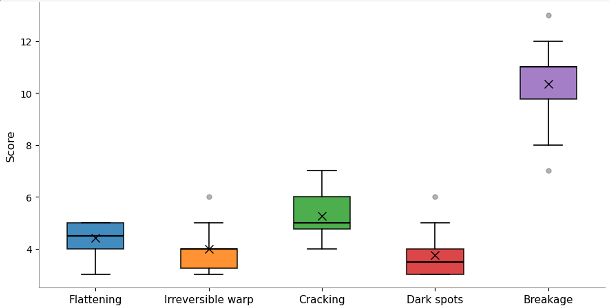
Figure 9 shows the results of the material fatigue testing caused by repeated bending of the SM-T. It shows that the initial indications of material damage came between three and six bending cycles for the different initial indications. Complete breakage happened after eight to 12 bending cycles.
Counts (Score) of bending cycles at which the first symptoms of material damage occurred, tested over 13 SM-Ts. Also, the bending cycle count at which complete failure occurred is depicted.

Figure 9 Long description
A box plot displays scores for five categories: flattening, irreversible warp, cracking, dark spots and breakage. Each category is represented by a box with a central mark indicating the median score. Flattening has a median score around 4, irreversible warp around 3, cracking around 5, dark spots around 2 and breakage around 11. The boxes show the interquartile range and whiskers indicate variability outside the upper and lower quartiles. Outliers are marked as individual points.
Learning curve for reliable SM-T forming by surgeons
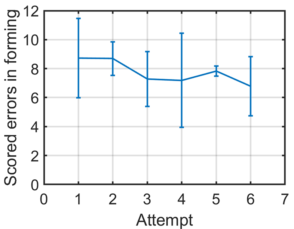
Figure 10 shows the learning curve during the production of six successive SM-Ts averaged over three ENT surgeons. The seventh attempt is not shown as not all surgeons managed seven attempts within the available time. It shows the score is reducing as attempts are increasing, meaning that each successive SM-T has less issues and is closer to the target geometry. No clear difference between surgeons could be found in bending performance. Overall, the SM-T dimensions for length and angle stayed within plus-or-minus 5 per cent deviation from intended size after the first two attempts were done, except the frontal offset angle that appeared to be more difficult to control.
Mean and standard deviation score over three surgeons for their successive attempts, visualising the learning curve for forming SM-Ts. Lower score means a SM-T with less forming errors.

Figure 10 Long description
A line graph showing scored errors in forming on the y-axis and attempt number on the x-axis, ranging from 0 to 7. The graph displays data points for six attempts, with error bars indicating variability. The scored errors start at around 10 for the first attempt, decrease slightly by the second attempt and show minor fluctuations through the sixth attempt, ending near 8.
Discussion
The aim of this article was to develop and validate an open-source design of a titanium TORP that can be easily obtained or produced locally in or for LMIC hospitals. The paper presented two designs, a 3D printed titanium design (3DP-T) and a sheet metal titanium design that can be bent into the desired shape with simple forming tools (SM-T). The SM-T matched better with the design requirements that were formulated, especially in terms of cost (EUR 9) and post-processing time (max 5 minutes). Critical dimensions were within 2.5 per cent accuracy. After forming the SM-T into shape the height was within 2.2 per cent and 4.5 per cent accuracy for shorter range and longer range SM-Ts, respectively
Sound transmission measurements with both TORP designs using a mechanical middle ear model showed transmission characteristics comparable to two typical commercial TORPs, across the generally accepted range for adequate speech understanding (0.5 – 4 kHz). Only above 4 kHz the performance is reduced, which is less relevant for human communication. The 4.5 mm 3DP-T was the closest match to commercial 4.5 mm TORPs. The 4.5 mm SM-T had a slightly lower transmission rate for higher frequencies. This likely is caused by zig-zag shape in the stem that reduces its stiffness. However, the improvement over having no prosthesis in the MMM was still evident.
Bench tests demonstrated bending and re-bending of the SM-Ts could be done safely for a maximum of three full re-bending cycles, after which initial signs of material damage started to appear; and complete failure occurred only after eight to 12 cycles. A fitting session on cadaver ears demonstrated a good fit of the SM-T, and no (potential) issues that might arise during surgery were found during fitting. Therefore, a good fit can be expected in most patients, and where needed, some peri-operative adjustments to patient-specific anatomy are easy and safe to perform.
A training session with ENT surgeons demonstrated the ease of bending SM-Ts, shaping usable SM-Ts after the initial two attempts. The learning curve showed that bending errors reduced with increasing attempts. These minor errors could be adjusted easily by the researcher to improve the SM-T and still yield usable SM-Ts. This means that those forming errors can easily be corrected afterwards, for instance, during an inspection by a second surgeon or peri-operatively. From these findings, it seems feasible and safe to use this low-cost SM-T design and production process in hospitals in LMICs.
After careful (ultrasonic) cleaning followed by steam sterilisation this SM-T design theoretically could be implemented in LMIC hospitals. All design files and bending instructions required to produce SM-Ts are openly available online.Reference Knulst, van Asperen, Gautam, Geerts, ten Have and Hou11 A next step would be a pilot study in which the SM-Ts are implanted in eligible patients to test the immediate and longer term hearing outcomes and to carefully monitor long term effects and record any adverse effects. The outcome of such a pilot and a clinical trial could allow formal approval of a new medical device to be sought through the appropriate national authorities. As this SM-T uses proven material (medical grade titanium) in a proven clinical procedure, and as cadaver fitting did not rise any concerns regarding geometry, it is anticipated that the outcomes of a pilot study and a clinical trial could be positive with results comparable to procedures using commercial devices.
• About 430 million people worldwide suffer disabling hearing loss, and conductive hearing loss accounts for 5–10 per cent of worldwide hearing loss cases
• Total ossicular replacement prostheses (TORPs) are common to restore conductive hearing loss
• However, TORPs are not readily available or affordable for use in low- and middle-income countries (LMICs)
• This study presents the design of a low-cost titanium sheet metal TORP for a material cost of 9 euros that can be produced locally in LMIC context
• This paper also presents the validation of the design, showing good results on precision, strength, sound transmission and on surgeons’ capabilities of shaping the sheet metal parts into usable TORPs
Conclusion
The aim of this article was to develop and validate an open-source design of a titanium TORP that can be easily obtained or produced locally in LMIC hospitals. (The devices could also be produced cheaply in bulk outside the LMIC and then bent to shape locally prior to sterilisation in country). This study shows that a 9 EURO titanium sheet metal TORP (SM-T) that is bent into shape using a few simple tools can be easily and reliably produced by local surgeons. Bench tests showed accurate dimensions and short learning curves for SM-T production by surgeons and also showed that complete bending/re-bending cycles to correct forming mistakes can be safely done several times. Moreover, the results showed that sound transmission properties of the SM-T, measured in an MMM, are comparable up to 4 kHz with some of the commercial TORPs used as a reference. Cadaver ear fitting sessions showed a good fit in the middle ear, without conflicts between SM-T and anatomical features.
Funding
Funding for producing 100 titanium SM-Ts has been received from the Delft Global Initiative, Delft University of Technology, The Netherlands.
Competing interests
The authors report no competing interests.



 Open access

