


1. Introduction
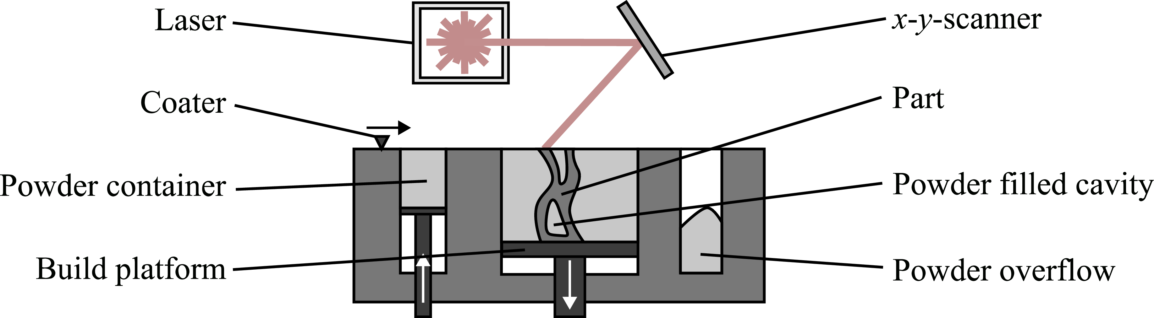
Additive manufacturing (AM) offers significantly greater freedom compared to conventional manufacturing processes due to its layer-by-layer manufacturing principle. A particular focus is on the powder bed fusion by laser beam of metals (PBF-LB/M) process, which is used to manufacture high-density components from loose metal powder (Reference Gibson, Rosen, Stucker and KhorasaniGibson et al., 2021; Reference Lachmayer, Ehlers and LippertLachmayer et al., 2024). This opens up the possibility of integrating functions and effects (Reference Ehlers, Meyer, Oel, Bode, Gembarski, Lachmayer, Lachmayer, Bode and KaierleEhlers et al., 2023). One effect that can be integrated into components is particle damping. A particle damper (PD) is characterized by loose particles in a closed cavity. In the event of vibration, energy dissipation occurs due to impact and friction interactions between particles and between the particles and the cavity wall. This minimizes vibrations and improves damping properties (Reference Scott-Emuakpor, George, Runyon, Holycross, Langley, Sheridan, O’Hara, Johnson and BeckScott-Emuakpor et al., 2018). The PBF-LB/M process offers the possibility of integrating PD directly into components by creating unfused closed cavities in the component. The powder material remaining in these cavities acts as an additively manufactured particle damper (AMPD) (Figure 1). This is a promising approach for reducing resonance responses, especially for topology-optimized lightweight structures with poor damping properties.
Enabled by further developments of PBF-LB/M system technology, it is now also possible to manufacture multi-material components in the PBF-LB/M process (Reference Schneck, Horn, Schmitt, Seidel, Schlick and ReinhartSchneck et al., 2021). The additional possibility of material selection creates an additional dimension in the degrees of freedom that can be used to increase the performance of PDs. The use of particle material with higher density is particularly promising, as an increase in particle mass results in increased damping (Reference Hollkamp, Gordon and DavisHollkamp & Gordon, 1998).
This article examines how the performance of AMPD can be improved. Therefore, a component of a real world application is optimized in a case study using the AMPD optimization tool developed by Oel et al. (Reference Oel, Roeder, Meyer and LachmayerOel et al., 2025b). The result is then manufactured using multi-material PBF-LB/M from high performance Scalmalloy® aluminum alloy with tungsten PD. The influence of the particle material on the damping properties is analyzed. In addition, the tasks in the AM process chain that require special steps in the manufacturing of multi-material AMPDs will be identified.
Manufacturing of an AMPD structure in the PBF-LB/M-process (Reference Oel, Roeder, Meyer and LachmayerOel et al., 2025a)

2. State of the art
2.1. Additively manufactured particle dampers
AMPDs are characterized by particle material being placed directly into the closed cavities during the manufacturing process. As with conventionally manufactured PDs, AMPDs exhibit nonlinear system behavior (Reference Ehlers, Tatzko, Wallaschek and LachmayerEhlers et al., 2021; Reference Fowler, Flint, Olson and InmanFowler et al., 2001).
The optimal frequency range and excitation level are influenced by the dimensions of the cavities (Reference Westbeld and HöferWestbeld & Höfer, 2025). It has been found that a certain minimum acceleration is required for sufficient particle motion to occur and lead to a damping effect (Reference Papalou and MasriPapalou & Masri, 1996; Reference Xu, Chan and LiaoXu et al., 2004). It has also been shown that the damping behavior depends heavily on the placement of the cavities within the component (Reference Hollkamp, Gordon and DavisHollkamp & Gordon, 1998; Reference Oel, Kleyman, Jonkeren, Tatzko and EhlersOel et al., 2024; Reference Westbeld and HöferWestbeld & Höfer, 2025). If the cavity is placed in a region of high vibration amplitude, the damping increases.
Another influencing factor is the mass of the particles. This can be achieved by using a particle material with a higher density and increasing the cavity volume (Reference Hollkamp, Gordon and DavisHollkamp & Gordon, 1998; Reference Masmoudi, Job, Abbes, Tawfiq and HaddarMasmoudi et al., 2016). Other influencing parameters are particle size and hardness. Smaller particles increase the number of interactions and thus increase energy dissipation (Reference Xu, Chan and LiaoXu et al., 2004). Damping can also be increased by using harder particles (Reference Sathishkumar, Mohanasundaram and KumarSathishkumar et al., 2014).
The investigation of the various influencing parameters was mainly carried out using test specimens. The integration of AMPD into components for real-world applications has so far only been demonstrated on turbine blades (Reference Niedermeyer, Ehlers and LachmayerNiedermeyer et al., 2023; Reference Scott-Emuakpor, Johnson and MiddendorfScott-Emuakpor et al., 2025), a motorcycle triple clamp (Reference Ehlers, Lachmayer, Pfingstl, Horoschenkoff, Höfer and ZimmermannEhlers & Lachmayer, 2021), gears (Reference Jonkeren, Ehlers, Dilworth, Marinone and FurlichJonkeren & Ehlers, 2024), and a wind tunnel instrumentation rake (Reference Celli, Janczewski, Sheridan, Scott-Emuakpor, Warner, Smith, Hollkamp, Napper and GeorgeCelli et al., 2023; Reference Kiracofe, Diaz, Postell, Celli, Hollkamp, Napper, Scott-Emuakpor and GeorgeKiracofe et al., 2023).
To support the design of AMPDs, design guidelines have been established (Reference Ehlers, Meyer, Oel, Bode, Gembarski, Lachmayer, Lachmayer, Bode and KaierleEhlers et al., 2023). In addition, an AMPD optimization tool has been introduced (Reference Oel, Roeder, Meyer and LachmayerOel et al., 2025a). For a given design space, this tool performs a topology optimization based on the minimization of strain energy. At the same time, cavities are integrated, with the objective of placing the largest possible cavity volume in regions of maximum vibration amplitude.
2.2. Multi-material PBF-LB/M
While only mono-material components could be manufactured using the PBF-LB/M process in the past, further developments in the material application system now make it possible to combine multiple materials (Reference Schneck, Horn, Schmitt, Seidel, Schlick and ReinhartSchneck et al., 2021). A distinction can be made between 2D and 3D multi-material structures (Reference Meyer, Messmann, Oel, Ehlers and LachmayerMeyer et al., 2023). The coating principles of patterning drums, spreading plus suction, vibrating nozzle, hopper feeding, and electrophotographic can be used to manufacture 3D multi-material structures (Reference MussattoMussatto, 2022). Previous studies have focused in particular on material combinations that can be used to generate locally increased electrical (Reference Oel, Rossmann, Bode, Meyer, Ehlers, Hackl and LachmayerOel et al., 2023) or thermal conductivity (Reference Meyer, Messmann, Ehlers and LachmayerMeyer et al., 2025; Reference Schneck, Horn, Schindler and SeidelSchneck et al., 2022). In all cases, the materials used are fused together. The use of multi-material AM for the production of multi-material AMPD is completely novel and has not yet been demonstrated. This work uses an Aerosint SPD 1.0 multi-material coater, which produces 3D multi-material components using patterning drums (Reference Meyer, Messmann, Oel, Ehlers and LachmayerMeyer et al., 2023).
3. Approach: Increased performance through topology and PD optimization and multi-material PBF-LB/M
The functionality and performance of AMPDs have been clearly demonstrated in the current literature. In addition, it has been shown for conventionally manufactured PDs that a higher particle mass has an effect on the component due to increased damping. Still, the manufacturing of multi-material AMPDs with powders that have a higher density than the structural material, has not yet been investigated. In addition, Oel et al. presented an AMPD optimization tool, but its functionality has not yet been validated in a real-world application (Reference Oel, Roeder, Meyer and LachmayerOel et al., 2025a). Therefore, this article pursues the approach of combined topology and particle damping optimization using the tool presented by (Reference Oel, Roeder, Meyer and LachmayerOel et al., 2025a) in conjunction with multi-material PBF-LB/M. The potential performance improvement of this approach for the application of an atom chip bracket is investigated in a case study. In addition to investigating the increase in component performance, the aim of the case study is to verify the suitability of the AM process chain according to Lachmayer et al. (Reference Lachmayer, Ehlers and LippertLachmayer et al., 2024) for multi-material PD.
4. Case study: Optimization and multi-material AMPD of an atom chip bracket for quantum inertial navigation sensor
The following section presents a case study on the optimization of a component in terms of its mass, stiffness, and damping, as well as multi-material AM. Based on this, the case study also shows how the development and manufacturing of multi-material AMPDs differ from the generic process chain for AM. A particular focus is placed on component optimization in the product design phase, the preparation of manufacturing data and the machine preparation in the pre-process, and the actual manufacturing process in the in-process.
The case study is being conducted on a bracket for an atom chip. The atom chip is a central component of a quantum gravimetry measurement system. On moving platforms, such as aircraft or satellites, it enables the detection of the gravitational field with high spatial resolution (Reference Kassner, Diekmann, Künzler, Petring, Droese, Dencker, Heine, Abend, Gersemann, Rasel, Herr, Schubert and WurzKassner et al., 2023). As part of the AeroQGrav project, a high-precision quantum gravimeter is to be developed and tested for use in aircraft and satellites. For this reason, the bracket for the atom chip is being optimized to reduce vibrations and thus the influence on the measurement results. At the same time, the aim is to achieve the lowest possible weight in order to reduce the overall mass of the measuring system for use in a satellite system as much as possible. To achieve this, the component design is being optimized using the AMPD optimization tool developed by Oel et al. and then manufactured using multi-material PBF-LB/M (Reference Oel, Roeder, Meyer and LachmayerOel et al., 2025a). The aluminum alloy Scalmalloy® is used as the structural material, while tungsten powder is intended for the particle-filled cavities.
4.1. Product design
The product design phase begins with a requirements analysis. This analysis defines the geometric requirements that determine the available solution space, as well as boundary conditions and other design requirements, such as the need for a single-piece component.
These requirements serve as the basis for component optimization using the AMPD optimization tool which is based on Python scripting within the FE software Abaqus (Reference Oel, Roeder, Meyer and LachmayerOel et al., 2025b). The boundary conditions for optimization consist of a fixed clamping and an acceleration of 1000 g, which acts on the mass of the bracket and the atom chip in all three spatial directions. The structural material used is the aluminum alloy Scalmalloy®, which has a density of 2.65 g/cm3. Tungsten powder with a density of 19.26 g/cm³ is used in the cavities. The optimization target is defined as a volume of 50% compared to the maximum solution space and a volume fraction of the cavities of 4%. Further optimization parameters, such as the filter radius before and during the integration of the cavities and the number of iterations before cavities are integrated into the component (PD-start), are determined based on previous experience during the development of the optimization tool and are listed in Table 1.
Parameters for topology and damping optimization

After optimization over 58 iterations, the result is the finite element (FE) mesh for the structural material (solid elements) and the cavity volume (PD elements). For further use in AM, it is necessary to smooth these mesh-based surface models and convert them into volume models so that the functional surfaces can be reconstructed. This is implemented using Rhino/Grasshopper software by first approximating the FE mesh before smoothing it using the Dendro plugin and applying an offset. The result is exported as a STEP file. In the Autodesk Fusion CAD program, the smoothed geometries of the solid volume and the PD volumes are divided from each other using Boolean operations. The functional surfaces are also reconstructed. The schematic process and the intermediate results of the individual steps of the product design phase are shown in Figure 2. The final component design has a volume of 16.42 cm³. The total mass consists of the mass of the structural material of 47.65 g and the expected mass of the unmelted tungsten powder of 1.98 g. This means that the total mass has been roughly halved compared to the original component. The final component design has an outer diameter of 58 mm and a hight of 19.5 mm.
Component optimization and geometry reconstruction of atom chip bracket

4.2. Pre-process
The manufacturing data for the PBF-LB/M process is generated using Autodesk Netfabb software. Special steps are required in component preparation for multi-material AMPDs, which are described below.
The available coater for multi-material application has an accuracy of 0.5 mm in the x and y directions for powder application, which is significantly lower than that of the laser scanner system. This means there is a risk that areas of the structural material that are melted by the laser will be coated with tungsten powder. As this has a negative impact on the structural properties, an offset is applied to the material transition region (Figure 3). Since the contour for powder application and the contour for laser melting are defined separately, the tungsten material contours of the cavities can be reduced in size. This shifts the material transition to the inside of the cavities, so that Scalmalloy® powder is placed in the cavities but no tungsten powder is placed in the structural material. The offset of the contours is set to 0.5 mm. When generating support structures, it must be ensured that these are not created in the cavities, as they have a negative effect on the damping behavior. Figure 3 shows the placement of the component with support structures in the build space and the offset of the material contour in the detailed view. The contours defining the Scalmalloy® and tungsten areas are exported as.cli contours. The laser vectors for fusing the structural material of the component are exported as an.ilt file. This also contains the laser parameters for fusing the Scalmalloy® powder, which were identified in preliminary tests and are listed in Table 2 together with the system-specific parameters for multi-material deposition.
In addition to the typical processes for the PBF-LB/M process, such as the precise alignment of the substrate plate to the coating plane, the preparation of the multi-material manufacturing system requires absolute calibration of the material application to the laser system in the x and y directions. A checkerboard pattern for calibration, which is generated with both powder materials and scanned by the laser, allows the coating and laser contours to be precisely aligned with each other.
Offset of material transition contour for multi-material atom chip bracket with AMPD

Figure 3 Long description
A diagram of additive manufacturing process showing the integration of particle damping in a component. Panel A: A close-up view of the material transition contour showing unfused Scalmalloy powder, fused Scalmalloy volume, and unfused tungsten powder. Panel B: A top view of the manufacturing setup showing the coating direction, fume extraction, and the placement of the component with integrated particle damper.
Parameters for laser processing and multi-material powder coating

4.3. In-process
The atom chip bracket is manufactured on an Aconity MIDI+ PBF-LB/M system equipped with an Aerosint SPD recoater. Manufacturing takes place at a layer thickness of 50 µm under an argon protective gas atmosphere.
Despite the calibration of the laser and material contour during system preparation, an increased pyrometer signal was observed in the immediate wall area of a cavity, as shown in Figure 4. This was corrected by adjusting the offset between the laser and material contours. Figure 5a shows the powder bed during the build process, in which the deposited tungsten powder can be seen alongside the Scalmalloy® powder. Inadequate powder application can be seen in the edge areas. The manufacturing of further variants of the bracket planned in this area was deactivated shortly after the start of the manufacturing process. Figure 5b shows the manufacturing result. A mono-material AMPD variant was manufactured in the mono-material process using a conventional coating system.
Pyrometry measurement of multi-material atom chip bracket with AMPD

Figure 4 Long description
Panel A: A cross-sectional view of a multi-material atom chip bracket. The bracket features a central circular cavity surrounded by irregularly shaped outer cavities. The section is color-coded, with a scale bar on the right indicating measurements in millivolts (mV), ranging from 750 to 1400. The colors transition from blue to red, representing different measurement values. Panel B: A magnified view of a specific region within the bracket, highlighted by a red rectangle in Panel A. This magnified section shows detailed internal structures with similar color coding and measurement values.
(a) Powder bed of multi-material PBF-LB/M process, (b) finished multi-material bracket

4.4. Post-process and finishing
Following manufacturing, the components are separated from the substrate plate and the functional surfaces are mechanically reworked. The components were analyzed by means of computer tomography (CT). The CT machine Royma RMCT 4000 was used. The results of the CT analysis are shown in Figure 6. The scan data of the mono-material PD variant of the bracket (Figure 6 a-c) show that the cavities are filled with powder, with a small air gap visible in the upper area. This also corresponds to what is reported in the literature. Due to the high X-ray absorption of tungsten, the CT-scan of the multi-material variant cannot be ideally reconstructed (Figure 6 d-f). However, the images show that tungsten is present in all cavities. The cavities are not completely filled with tungsten, as can be seen in particular in the narrow cavities. This may be due to the offset of the material contour used in the pre-process.
CT analysis of atom chip bracket variants: (a-c) mono-material AMPD, (d-f) multi-material AMPD

Figure 6 Long description
Panel A: A grayscale image of a mono-material additive manufacturing particle deposition (AMPD) bracket viewed from an angle, showing internal structures and cavities. Panel B: A cross-sectional view of the mono-material AMPD bracket, displaying a circular inner cavity with a scale bar indicating 20 millimeters. Panel C: A close-up cross-sectional view highlighting an air gap and unfused powder within the mono-material AMPD bracket, with a scale bar indicating 2 millimeters. Panel D: A grayscale image of a multi-material AMPD bracket viewed from an angle, showing internal structures and cavities. Panel E: A cross-sectional view of the multi-material AMPD bracket, displaying a circular inner cavity with labels indicating Scalmalloy and a scale bar indicating 15 millimeters. Panel F: A cross-sectional view of the multi-material AMPD bracket, displaying a circular inner cavity with labels indicating Tungsten.
In order to analyze the dynamic behavior of the different bracket variants, the components were analyzed on a shaker system. The aim of the investigation is to examine energy dissipation at different frequencies and accelerations. For this purpose, the component is mounted on an adapter plate, which in turn is connected to a force sensor. Acceleration sensors are used to control the shaker system on the base plate and record the acceleration signal on the atom chip dummy. The test setup is shown in Figure 7. The shaker is used to generate sinusoidal vibrations for 13 acceleration measurement points ranging from 50 to 212.5 m/s2 and 8 frequency measurement points ranging from 250 to 2000 Hz. The frequency range <1000 Hz is of particular interest for mobile use of the gravimeter in satellites or aircraft. The acceleration and force signal are used to calculate the dissipated energy EDiss according to Guo (Reference Guo, Yoneoka and TakezawaGuo et al., 2024):


Figure 8 shows the dissipated energy for the two variants with integrated mono- and multi-material AMPD at different frequencies and accelerations. It can be seen that significantly higher values for EDiss are achieved for lower frequencies. In addition, EDiss also increases with increasing acceleration. Between the two AMPD variants, it can be observed, especially for frequencies up to 1000 Hz, that the multi-material variant generates significantly higher energy dissipation. However, at a frequency of 1500 Hz and 2000 Hz, only a small difference can be detected.
Setup for experimental testing: (a) schematic representation, (b) real setup

Calculated dissipated energy at different frequencies and accelerations for mono- and multi-material AMPD

Figure 8 Long description
The image contains six line graphs showing the dissipated energy at different frequencies and accelerations for mono- and multi-material AMPD. Each graph represents a different frequency: 250 Hz, 500 Hz, 750 Hz, 1000 Hz, 1500 Hz, and 2000 Hz. The x-axis of each graph represents acceleration in meters per second squared (m/s^2), ranging from 0 to 200 m/s^2. The y-axis represents the dissipated energy (E_Diss) in joules (J), with different scales for each graph. The blue line represents multi-material AMPD, and the orange line represents mono-material AMPD. Panel A: The graph at 250 Hz shows that the dissipated energy for multi-material AMPD increases significantly with acceleration, while the dissipated energy for mono-material AMPD remains relatively low. Panel B: The graph at 500 Hz shows a similar trend, with multi-material AMPD having higher dissipated energy than mono-material AMPD as acceleration increases. Panel C: The graph at 750 Hz continues this pattern, with multi-material AMPD showing a steeper increase in dissipated energy compared to mono-material AMPD. Panel D: The graph at 1000 Hz shows a more pronounced increase in dissipated energy for multi-material AMPD, while mono-material AMPD shows a slight increase. Panel E: The graph at 1500 Hz indicates that both multi-material and mono-material AMPD show an increase in dissipated energy with acceleration, but multi-material AMPD has a higher rate of increase. Panel F: The graph at 2000 Hz shows that both materials exhibit an increase in dissipated energy, with multi-material AMPD having a higher dissipated energy overall.
5. Discussion
Based on the case study, several activities in the AM process chain can be identified that require additional steps for multi-material of AMPD using PBF-LB/M. One example is the increased effort required in the product design phase. Although the design freedom gained through the choice of materials offers the possibility of designing more efficient components, this degree of freedom must also be controlled. This requires the relevant knowledge to be available and the design tools used to be able to take different material properties into account in their optimization strategies. The AMPD optimization tool used was successfully applied to the atom chip bracket application. The defined targets for component volume and cavity ratio were achieved. However, the result of the optimization cannot be manufactured directly; first, smoothing and reconstruction of the functional surfaces is necessary. Moreover, the handling of geometry files is also more complex, as multiple CAD models are required for multiple materials, and these must be consistent with each other.
With regard to the pre-process, it is clear that there are powerful software solutions for PBF-LB/M manufacturing, but their range of functions for multi-material manufacturing has its limits. For example, offsets for material transitions must be created manually, and separate steps are required to generate the contours for material application and the laser vectors. Due to the significantly more complex system technology of multi-material AM, additional steps are necessary to adjust and calibrate the powder application system.
In-process manufacturing is automated, but the process stability is lower than for conventional single-material manufacturing. Based on the offset of the contours, it has been shown that measuring instruments for process monitoring, such as the pyrometer used, are a valuable tool for checking the correct manufacturing of the component. Likewise, suitable procedures are necessary in quality assurance to distinguish between the materials used. Experimental investigation of the manufactured components using shaker excitation has shown that the energy dissipation of the integrated AMPD could be significantly increased, particularly in the frequency range up to 1000 Hz. No significant difference between the mono- and multi-material variants is apparent in the frequency range from 1250 to 2000 Hz. This can be explained by the fact that particles of different densities reach certain states of motion at different frequencies. However, the measurements also show that energy dissipation occurs in both variants across the entire frequency range investigated. Furthermore, the measurements performed do not cover the behavior in the case of resonance, as the natural frequencies of the component are not within the operating range of the shaker used.
The results also show that additional investigations are necessary for the ideal design of multi-material AMPD in order to identify the material-dependent optimums for damping behavior in the frequency and acceleration range. This is necessary in order to achieve a significant increase in performance through the use of multi-material PBF-LB/M manufacturing and thus justify the significantly higher effort along the AM process chain compared to mono-material AM.
6. Conclusion and outlook
The optimization and multi-material AM of the atom chip brackets carried out as part of the case study was successfully completed. The defined target volume and the integration of the cavities were achieved.
With regard to the AM process chain, the following findings were made for the manufacturing of multi-material AMPD using PBF-LB/M:
-
• The additional degree of freedom resulting from material variation must be controlled. This requires specific knowledge for the design and optimization of components.
-
• The preparation of machine data for multi-material AM is significantly more complex, especially since software solutions for preparing a build job do not include the necessary functionalities.
-
• The system technology for multi-material PBF-LB/M is significantly more complex and increases the effort required for system preparation considerably. Likewise, the lower process stability increases the probability of errors in the build process.
The experimental characterization of the mono- and multi-material variants of the atom chip bracket has shown the following:
-
• Depending on the particle density, different energy dissipation levels can be observed. In particular, the frequency-dependent behavior varies. At frequencies below 1000 Hz, the use of tungsten as the particle material can increase energy dissipation by a factor of 4 to 17 compared to the mono-material variant.
-
• Investigations at resonance are necessary for the validation of the atom chip bracket.
-
• Extensive investigations are necessary for a detailed understanding of the damping behavior of multi-material AMPD.
Further research activities will examine the influence of the modified particle material in detail using test specimens. In particular, differences in frequency- and acceleration-dependent behavior must be identified.
Acknowledgement
The project “Development methodology for laser powder bed fused lightweight structures with integrated particle dampers for vibration reduction” was funded by the Deutsche Forschungsgemeinschaft (DFG, German Research Foundation) - Project number 495193504.
We would also like to thank Alexander Kassner from the Institute of Micro Production Technology at Leibniz University Hannover for providing information on quantum gravimetry and the atom chip bracket.






 Open access

