


1. Introduction
Power electronics system design has evolved significantly in recent years, shifting from conventional distributed configurations to highly integrated, modular architectures. (Reference Alizadeh and Alan MantoothAlizadeh & Alan Mantooth, 2021). Traditionally, power electronics assemblies comprised separate submodules: converters, filters, and control units, each housed individually and connected via complex wiring harnesses (Reference März, Schletz, Eckardt, Egelkraut and RauhMärz et al., 2010; Reference Xu, Lin and BlaabjergXu et al., 2021). While this approach allowed functional separation and easier maintenance, it led to underutilized internal volume, higher mass, and limited scalability. These drawbacks, along with the demand for greater efficiency, power density, and manufacturability in electric and hybrid vehicles, have driven the shift toward compact, multifunctional, and thermally optimized designs (Reference Samuel and AlexanderSamuel & Alexander, 2024; Reference Shimin, Varsha and MakarandShimin V V et al., 2016).
Modern power electronics development adopts a holistic approach, integrating electrical, mechanical, and thermal design within a unified framework. Modularity is maintained, not for physical separation, but as a strategy for functional organization in a single integrated housing (Reference Lee, Daan Van Wyk, Boroyevich and BarbosaF.C. Lee et al., 2002). Each module filtering, conversion, or control can be individually designed, validated, and replaced, contributing to a more efficient, compact system. This modular integration reduces part count, standardizes interfaces, simplifies assembly, and enhances reliability, supporting design-for-manufacturability and design-for-maintainability principles. (Reference Pinto, Riondet, Rio, Lembeye and CrebierPinto et al., 2025). In parallel, design-for-compactness and design-for-thermal-management principles are applied to maximize spatial efficiency and ensure effective heat dissipation. Direct liquid cooling plates, conduction-optimized layouts, and thermally conductive materials are adopted to maintain safe operating temperatures while minimizing volume (Reference Abo-Zahhad, Amine Hachicha, Said, Ghenai and OokawaraAbo-Zahhad et al., 2022). A key performance metric guiding this evolution is power density, which expresses the electrical power delivered per unit volume:

where P is power (W) and V is system volume (L). Higher power density indicates a more compact and efficient system, reflecting optimized use of space, materials, and thermal management (Reference Mahesh, Vinoth Kumar, Abebe, Udayakumar and MathankumarMahesh et al., 2021; Reference SaitoSaito, 2014).
However, as systems become more compact and integrated, their mechanical, thermal, and electromagnetic interactions grow more complex. Therefore, simulation-driven design has become indispensable in the validation process. Structural analyses ensure mechanical integrity under vibration and impact; thermal simulations predict temperature distribution and cooling efficiency; and electromagnetic simulations evaluate shielding effectiveness and compliance with automotive EMC standards. Finite element and computational fluid dynamics tools enable these multidisciplinary analyses, providing early insights into stress distribution, heat flow, and electromagnetic fields (Reference Hassan, Rajaguru, Stoyanov, Bailey and TilfordHassan et al., 2024; Reference Mohammad Shahjalal and BaileyMohammad Shahjalal et al., 2014). These virtual validations allow early identification of design weaknesses, reducing the need for iterative prototyping and ensuring that final systems meet safety, performance, and reliability requirements (Reference Rasool, El Baghdadi, Rauf, Zhaksylyk, D’hondt, Sarrazin and HegazyRasool et al., 2022). Altogether, the integration of modular design principles, “design-for” methodologies, and simulation-based validation defines the current state of the art in power electronics engineering leading to lighter, smaller, and more efficient systems suited for the next generation of electrified transport.
Although extensive research addresses power electronics miniaturization, thermal management, and structural robustness, these aspects are often treated separately. Structural studies typically focus on vibration and shock resistance, while thermal analyses emphasize heat dissipation and cooling performance. Modularization is often approached from packaging or scalability perspectives, with limited integration into regulation-oriented validation frameworks. However, few studies propose integrated redesign methodologies that simultaneously address (i) automotive regulatory compliance, particularly UN ECE Regulation No. 100, (ii) modular architectural optimization based on Design for Excellence (DfX) principles, and (iii) combined thermo-mechanical validation within a unified simulation-driven development workflow. This work addresses the gap by proposing and validating an integrated casing redesign framework for automotive power electronics. The methodology combines modular internal reconfiguration, DfX-driven structural simplification, mechanical assessment (regulatory shock validation), thermal assessment, and efficiency comparison within a unified process. It is demonstrated on an industrial system for M2 and N2 vehicles, achieving significant reductions in volume and weight while increasing power density.
2. Problem statement
AddVolt is a technology leader committed to making goods transportation more sustainable, cleaner, and quieter. Through its world-first plug-in hybrid system for refrigerated transport, the company enables electric operation of refrigeration units, significantly reducing emissions and noise while improving drivers’ quality of life. To remain competitive, AddVolt identified the need to optimize its power electronics subsystem. The current system measures 989 × 228 × 551 mm (124 L), weighs 84 kg, and delivers 19 kW with 27 kWh capacity, corresponding to a power density of 153 W/L. It consists of independent functional submodules housed in AISI 304L stainless-steel enclosures, leading to inefficient space utilization and underused internal volume. This configuration increases production costs, limits scalability, and reduces long-term reliability, while the large number of separate components adds system complexity, assembly time, and potential failure points.
Although the system meets current operational requirements, its modular, component-intensive design limits efficiency, manufacturability, and scalability. To address this, AddVolt proposes a new integrated power electronics system that consolidates existing submodules into a single optimized enclosure, incorporating an effective cooling system and a single high-voltage connection to the battery pack. Mechanically, the system was designed to fit within target dimensions of 600 mm (L), 350 mm (W), and 100 mm (H), with a weight goal of 50 kg, subject to adjustment based on integration requirements. Structurally, the pack must withstand real operating loads and pass equivalent numerical analyses without permanent deformation or failure. Concurrently, from a thermal perspective, the system must operate safely under extreme conditions, ensuring no component exceeds 125 °C. By integrating the power electronics into a compact, optimized enclosure, AddVolt aims to deliver up to 20 kW (15 kW average) while supporting 30–40 kWh battery capacities. The design increases power density, improves thermal management and efficiency, and simplifies manufacturing for scalable, cost-effective production. An integrated, simulation-driven approach combining modular, thermal, and structural optimization was adopted to develop a compact, reliable, and high–power-density solution for sustainable transport.
3. Materials and methods
The proposed methodology follows a structured and iterative development workflow for the redesign of an automotive power electronics casing, DfX-driven modular optimization, and unified thermo-mechanical validation (Figure 1). The process begins with the requirements definition stage, where mechanical, electrical, packaging, and vehicle integration constraints are consolidated. This phase explicitly incorporates regulatory load cases and safety criteria, ensuring that compliance considerations are embedded from the outset of the design process.
Methodology flowchart applied to the iterative design process

Figure 1 Long description
The flowchart illustrates the iterative design process for power electronics system design. The process begins with design iteration, which includes requirement definition, concept architecture, layout and packaging, and material and technology selection. The design is then verified against design for excellence (DfX) principles, including modularity, manufacturability, compactness, lightweight, assembly and disassembly, thermal management, reliability and safety, and sustainability. If the design is not verified, it returns to the design iteration stage. If verified, the process proceeds to structural simulations, which involve model setup, analyses, metrics and acceptance, and output and automotive regulatory compliance validation. If the structural simulations are not passed, the process returns to the design iteration stage. If passed, the process moves to thermal simulations, which also involve model setup, analyses, metrics and acceptance, and output and decision. If the thermal simulations are not passed, the process returns to the design iteration stage. If passed, the process proceeds to validation.
Based on these boundary conditions, the concept development phase establishes the modular architectural configuration of the casing. Internal layout reconfiguration, material selection, and structural simplification are further verified by DfX principles. This stage aims to reduce part count, simplify structural interfaces, improve manufacturability, and enhance scalability while preserving mechanical and thermal integrity. The outcome is a baseline modular design prepared for numerical assessment. The workflow then advances into a coupled thermo-mechanical simulation loop. Structural simulations evaluate the casing’s response under operational and inertial loads, including regulatory compliance scenarios defined by UN ECE R100. In parallel, thermal simulations analyse heat generation, and temperature distribution under representative operating conditions, ensuring that maximum allowable temperatures and thermal uniformity criteria are satisfied. If structural compliance is not achieved, or if modularity, compactness, or other DfX principles are compromised, the workflow returns to the redesign stage. Layout modifications, structural refinements, or packaging adjustments are implemented, and the analyses are repeated. This iterative loop continues until regulatory, thermo-mechanical, and DfX requirements are simultaneously fulfilled. Once all criteria are satisfied, the methodology proceeds to the validation phase, where the final integrated design is experimentally verified and correlated with simulation results. This structured, simulation-driven workflow ensures that modular optimization, regulatory compliance, and thermo-mechanical performance are addressed concurrently within a unified development process.
3.1. Casing redesign
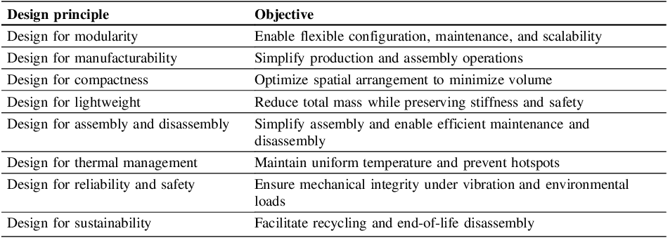
For redesign, the casing was modelled in SolidWorks 2023, allowing parametric optimization of geometry, assembly interfaces, and internal component layout to evaluate manufacturability, modularity, and spatial efficiency. The redesigned power electronics system includes key components for energy conversion, control, and filtering, with a total mass of 15 kg: one auxiliary inductor (ACL1), six main filter inductors (ACL2), four IGBTs with gate drivers (max dissipation 6670 W), and dedicated modules for AC/DC conversion (DVRPO), DC-DC regulation/protection (DRIPO), AC-side filtering/control (FIBOAC), DC bus capacitance (FIBOCAP), and EMI filtering (FIBOEMI). The casing uses an aluminium baseplate and glass-fibre reinforced polyamide closure. The redesign followed a structured Design-for-Excellence (DfX) framework, applying integrated principles to geometry, materials, and assembly to ensure functionality, manufacturability, and long-term sustainability, which are described in Table 1.
Design for principles considered for power electronics case redesign

The parametric optimization was conducted through a structured manual iterative design approach. Key geometric variables, including enclosure dimensions, module positioning, internal clearances, baseplate and closure thicknesses, were defined as editable parameters in the CAD model. Design variants were generated through controlled manual adjustment of these parameters to improve compactness, manufacturability, and assembly feasibility while satisfying dimensional constraints. The CAD models were subsequently exported to ANSYS for structural and thermal simulations. Geometry modifications and simulation analyses were performed iteratively with manual data transfer between platforms, enabling simulation-driven refinement of the final configuration.
3.2. Structural simulation
The structural assessment of the power electronics was performed in ANSYS Mechanical using the finite element method, following UN ECE Regulation No. 100 (Revision 3) for M2 and N2 vehicles. The workflow included: (1) static analysis to determine pre-stress from gravity; (2) modal analysis to extract natural frequencies and mode shapes; and (3) transient response analysis under shock loading, linked to the modal analysis to share geometry, boundary conditions, and data. The mode-superposition method was used for the transient analysis. Table 2 illustrates the input acceleration data for the shock testing.
Input acceleration data for the transient response analysis

Prior to meshing, the model geometry was simplified by removing non-structural features to reduce computational cost while preserving mechanical accuracy. Top composite cover was designed through Ansys Composite Prep application. All resultant components were designed as solid elements. Fastening elements were idealized as beam connections for a faster solution. A mesh refinement convergence study was performed at the hex-standoffs and U-shaped profiles that fix the PCBs. Final elements size of 1.0 and 1.5 mm were defined for the U-profiles and hex-standoffs, respectively (features can be seen in Section 4.1 – Casing redesign). The final model exhibited a combination of hexahedral and tetrahedral type elements, an average quality of 0.75, an average aspect ratio of 2.49 and a total of 2500000 degrees of freedom. The components defined by composite materials were evaluated by the inverse reserve factor (IRF) failure mode measure, available in Ansys Composite Post application. Metal components were evaluated by the maximum equivalent stress (von Mises criteria) and maximum total deformation.
3.3. Thermal simulation
Thermal simulations were conducted in ANSYS Fluent to assess temperature distribution and heat transfer within the power electronics and battery pack enclosures. Models included key heat-generating components: coils and IGBTs in the power electronics, battery modules in the battery pack, and enclosure structures. Heat conduction, natural convection, and external heat exchange were considered, with realistic boundary conditions. Component losses were assigned as 150 W (ACL1), 20 W (each ACL2), 1600 W (IGBTs), totalling 6670 W in the power electronics enclosure, and 153 W per battery module. External surfaces had a convective coefficient of 10 W/m²·K at 60 °C, while radiative effects were neglected. The cooling system used water at 20 °C and 0.1 kg/s to reproduce standard operating conditions.
4. Results and discussion
This chapter presents the design of the power electronics, together with the corresponding structural and both thermal simulations. The development followed the established flowchart methodology and involved multiple iterations supported by simulation analyses. However, only the final optimized configuration is reported here, as it reflects the consolidated outcome of the redesign process.
4.1. Casing redesign
Following the reduction of the power electronics components, a new configuration was analysed to further minimize volume. Accordingly, design-for-compactness principles were applied during development, and three configurations were evaluated (dimensional data are shown in Table 3, while the configurations and their corresponding volumes are illustrated in Figure 2). Solution 1 arranged components flat, meeting requirements but leaving central space unused, with a volume of 15.16 dm3. Solution 2 moved key modules (FIBOAC, FIBOCAP, FIBOEMI) to the centre, reducing volume to 14.43 dm³ but increasing height beyond targets. Solution 3 combined both strategies, placing FIBOCAP and FIBOEMI horizontally in the centre while keeping other components flat, achieving maximum compactness with a total volume of 13.32 dm³ and meeting all dimensional constraints (the most restrictive constraint).
Dimensional comparison of power electronics configurations versus design requirements

Power electronics component arrangements and corresponding volumes

Modularity in the power electronics pack is a key design principle that enables flexibility, maintainability, and scalability. In Solution 3, the pack is organized into three distinct modules: the coil region, the central PCB area, and the suspended zone housing the filter and conditioning modules. Each module performs a specific function, allowing engineers to isolate, replace, or upgrade components without affecting the rest of the system.
This modular separation enhances reliability by preventing failure propagation, improves thermal management through targeted cooling, and simplifies electrical integration. It also supports standardization, allowing independent manufacturing and testing of each module. By defining clear mechanical and functional boundaries, the design enables automated assembly, reduces wiring complexity, and lowers production costs. Furthermore, modularity promotes sustainability by facilitating maintenance or recycling, resulting in a compact, flexible, and easily scalable power electronics pack. To enhance modular independence and performance, busbars were designed for the main electrical connections, following design-for-manufacturability principles. Their standardized geometry simplifies assembly, reduces wiring complexity, and supports automated production, lowering costs and improving consistency. Additionally, busbars contribute to a compact layout and sustainable design by enabling easy material recovery. Complementary plastic combs and adaptable plates were modelled to align with the busbars’ orientation, securing them to the enclosure while reducing component diversity, simplifying assembly, and supporting efficient end-of-life disassembly (Figure 3a).
Power electronics pack design and casing: (a) Internal layout with coils, central and suspended PCB regions, busbars and plastic fixtures. (b) Aluminium base plate contoured cavity

The application of the previous design principles reinforced the design for assembly and disassembly by enabling a modular system architecture and the adoption of busbars, simplifying installation and maintenance while reducing cable count and electrical interferences. With the internal layout defined, the external casing was designed following design-for-lightweight principles, optimizing material use and structural configuration to minimize mass while maintaining strength and durability. Design for assembly was also applied with a contoured cavity in the aluminium base plate to house the electronic components, including the power electronics assembly, ensuring precise alignment, enhanced mechanical stiffness, and improved vibration resistance for greater system robustness and quick mounting (Figure 3b).
Power electronics pack enclosure: (a) external casing with reinforced polyamide walls and lid, (b) peripheral electrical connections

The adoption of reinforced polyamide for upper and lateral sections aids to reduce the overall mass, offering low density, high mechanical performance, and thermal stability. The use of polymeric materials also enables complex geometries (e.g., using additive manufacturing), supporting efficient assembly, sealing integration, and end-of-life recyclability (Figure 4a). The peripheral regions of the casing, house the connection interfaces, ensuring accessible electrical connections while maintaining structural integrity (Figure 4b).
Aligned with thermal management principles and in contact with the enclosure base, power-dissipating components have a dedicated cooling plate that provides direct thermal contact, efficiently removing heat. Optimized channels direct fluid through high-heat regions, enhancing convective transfer and reducing temperature gradients, improving thermal performance, reliability under high loads, and overall system longevity.
With the integration of electrical components, inter-module connections, the enclosure, and peripheral components, the pack weighs ∼31 kg with dimensions of 533.34 × 403.34 × 127 mm, while the cooling plate adds 11.5 mm in height and 4.93 kg. Consolidating all components into a single optimized enclosure with the integrated cooling plate, the final pack achieves a maximum power density of 671 W/L and an average of ∼504 W/L, providing a highly compact and efficient design for 20 kW peak and 15 kW nominal output. The pack’s width and height slightly exceed original targets due to component dimensions and the need for unobstructed assembly to meet operational requirements.
4.2. Structural simulation
A total of 40 mode shapes were calculated. From the effective mass ratio output, modes 23, 14 and 28 were the most relevant for X (vertical), Y (transverse) and Z (longitudinal) directions (Figure 5), respectively. These modes indicated a probable resonance at U-shaped profile, FIBOEMI PCB and top cover, at frequencies higher than 200 Hz, which did not compromise model’s structural integrity (United Nations, 2023).
Mode shapes with the highest effective mass ratio in X, Y, and Z directions (left to right)

The transient response analysis results indicated a maximum Y-axis directional deformation of 0.77 mm at FIBOEMI PCB, which did not result in a contact with other components. For the same direction, a maximum equivalent stress of 194 MPa was calculated at U-shaped profile, near the fastener’s connection with the standoff, as illustrated in Figure 6. For the Z direction, a maximum direction deformation of 0.32 mm was calculated for the FIBOEMI PCB, not compromising model’s structural integrity. A maximum equivalent stress of 258 MPa was determined at the hex-shaped standoffs, as illustrated in Figure 2, due to the contact with the component below.
Equivalent stress results’ contour for the U-shape profile and hex-shaped standoff, in Y and Z directions’ analysis, respectively

Figure 6 Long description
Panel X: A heat map representing equivalent stress in the transverse direction for a U-shape profile. The map uses a color scale ranging from 0.10594 to 194.25 MPa, with blue indicating lower stress and red indicating higher stress. The maximum stress value is 194.25 MPa, and the minimum is 0.10594 MPa. The stress distribution shows higher stress concentrations in specific areas, particularly around the bends and holes. Panel Y: A heat map representing equivalent stress in the longitudinal direction for a hex-shaped standoff. The color scale ranges from 0.44602 to 258.11 MPa, with blue indicating lower stress and red indicating higher stress. The maximum stress value is 258.11 MPa, and the minimum is 0.44602 MPa. The stress distribution shows higher stress concentrations around the edges and corners of the hex-shaped standoff.
These results demonstrated an allowable result set that would comply with the international shock standard. Moreover, further non-linear analysis could be performed to evaluate plastic behaviour and validate the assumption of a lower final stress output. Nevertheless, present linear analysis was sufficient for design optimization and experimental validation.
4.3. Thermal simulation
Using defined material, heat generation, and ambient boundary conditions, a numerical simulation predicted the thermal response of the power electronics under extreme conditions. Figure 7 shows temperature concentrations at power-dissipating components and the gradient increase across the enclosure walls.
Temperature distribution for (a) the enclosure, (b) IGBT’s and (c) the baseplate

Figure 7 Long description
Panel A: A 3D model of an enclosure with a color gradient indicating temperature distribution. The temperature scale ranges from 20 degrees Celsius to 100 degrees Celsius, with blue representing cooler areas and red representing warmer areas. Panel B: Four cross-sectional views of IGBTs with a color gradient indicating temperature distribution. The temperature scale ranges from 20 degrees Celsius to 100 degrees Celsius, with blue representing cooler areas and red representing warmer areas. Panel C: A cross-sectional view of a baseplate with a color gradient indicating temperature distribution. The temperature scale ranges from 20 degrees Celsius to 100 degrees Celsius, with blue representing cooler areas and red representing warmer areas.
Regarding the enclosure, the highest temperature was observed in the IGBTs. Localized hotspots in these components reached a temperature of approximately 100 °C. The IGBTs are critical components with a high amount of heat dissipated. However, the use of a liquid cooling system allowed obtaining acceptable temperatures in these components, considering its limit temperature (125°C). The other components, while operating at lower temperatures than the IGBTs, do not approach their critical failure temperatures. The results demonstrate that the designs proposed for the analyzed enclosures effectively limit temperature increase within the battery pack and power electronics, thus maintaining all components within their recommended thermal limits.
While this study employed sequential (decoupled) structural and thermal simulations, measures as consistent boundary conditions, were used to reduce uncertainties and better approximate coupled behaviour. Although this approach does not account for temperature-dependent material properties, thermally induced stresses, or deformation–heat transfer interactions, conservative material choices and safety margins provided sufficient accuracy for preliminary validation and regulatory shock compliance. To further enhance predictive reliability, a stepwise roadmap toward strong multiphysics coupling is envisioned for future work. This includes implementing fully coupled thermo-mechanical simulations with temperature-dependent material models, incorporating deformation-induced contact variations, integrating electromagnetic–thermal interactions to account for Joule heating and local loss distribution, validating coupled simulations against experimental data, and iteratively refining design and material selection based on multiphysics results. Such a strategy will provide a more comprehensive assessment of system behaviour and long-term reliability under operational conditions.
4.4. Efficiency comparison
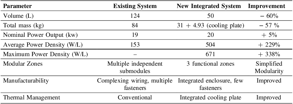
As previously described, the existing power electronics system, with overall dimensions of 989 × 228 × 551 mm (124 L) and a total mass of 84 kg, delivers a nominal power output of 19 kW, corresponding to a power density of approximately 153 W/L. The original system, though functional, suffers from inefficient use of internal volume due to its modular, component-heavy design, limiting manufacturability, scalability, and efficiency. The new integrated power electronics pack overcomes these issues with a compact, unified architecture, combining submodules into a single enclosure organized into three functional zones: coil region, central PCB area, and suspended module zone. This configuration enhances modularity and maintainability, allowing independent access to functional sections. The optimized design weighs 31 kg with dimensions 533.34 × 403.34 × 127 mm (50 L) with the cooling plate adding 11.5 mm and 4.93 kg. It achieves a maximum power density of 671 W/L (+338%) and an average of 504 W/L (+229%), while reducing weight by 57% versus the original pack. A comparative summary of key parameters for the two prototypes is presented in Table 4.
By combining compactness, modularity, and improved manufacturability, the new design delivers an efficient, scalable solution for advanced power electronics. Despite a slight volume increase, it achieves higher power density, thermal efficiency, and reliability, as confirmed by simulations. Overall, the optimized design demonstrates that integration and design-for-excellence principles can produce a lighter, more efficient, and thermally robust solution for next-generation electrified transport.
Comparative overview of existing and new integrated power electronics prototypes

5. Conclusions and future works
This work addressed a methodology proposal integrating regulatory modular architectural redesign guided by DfX principles, and combined thermo-mechanical assessment with regulatory shock validation within a unified development workflow. The results demonstrate that such an integrated approach enables substantial improvements in compactness, weight reduction, and power density, while ensuring compliance with automotive regulatory requirements for AddVolt’s power electronic system. By consolidating multiple submodules into a single optimized enclosure with three functional zones, the new design not only enhances maintainability and facilitates independent module handling but also surpasses many market offerings in power density, thermal performance, and manufacturability.
The pack’s mechanical and thermal performance was validated through simulations. Structural analyses confirmed the robustness of critical components under vibration and shock, while thermal simulations verified effective heat dissipation via the optimized cooling plate, keeping all electrical components within safe temperature limits. Mechanically optimized, the pack maintains structural integrity while reducing mass, contributing to a lighter, more manufacturable, and scalable solution. Most notably, the new system achieves a maximum power density of 671 W/L (338% improvement over the existing design) and an average power density of 504 W/L (229% increase), while simultaneously reducing weight by approximately 57%. These enhancements demonstrate that, despite slightly exceeding dimensional requirements, the redesigned power electronics pack delivers a compact, reliable, and high-performance solution with superior modularity, thermal management, and manufacturability, suitable for sustainable transport applications.
Future works should refine the dimensional requirements of the power electronics pack to meet target size specifications without compromising power density, weight reduction, or modularity. Additionally, a fatigue assessment under representative automotive vibration and thermal cycles, incorporating PSD-based random vibration analysis and thermo-mechanical fatigue evaluation of critical components to ensure long-term reliability will also be performed. As discussed in Section 4.3, future developments will include fully coupled multiphysics simulations, validated against experimental data, to further enhance predictive accuracy and long-term reliability assessment. Electromagnetic (EM) shielding must also be assessed, as it is a critical requirement in automotive electronic systems due to the increasing integration of electronic components. Recent studies show that continuous carbon fiber–reinforced composites provide high shielding effectiveness (SE): 40 dB attenuates more than 99.9% of incident radiation, while 4–8-layer prepregs (1–3 mm) can exceed 60 dB, achieving attenuation above 99% (Banerjee, R. et al., 2023; Munalli et al., 2019). The selected composite materials show promise for excellent EM shielding, but SE simulations or prototype testing per ISO 11452, CISPR 25, and ASTM D4935 are needed for validation (In Compliance, 2016). Complementary work will involve prototyping, testing, and validating the power electronics system—including thermal, vibration, manufacturability, and assembly assessments—to ensure a robust, automotive-ready solution. A cost analysis will also assess the economic benefits of the new design versus the original casing.
Acknowledgement
This work was developed within the scope of the project “NGS – New Generation Storage” [C644936001-00000045], financed by PRR – Plano de Recuperação e Resiliência under the Next Generation EU from the European Union.






 Open access

