

1. Introduction
Wireless power transfer (WPT) to implantable devices has attracted significant attention in the last decade. It is a promising choice for delivering power to the implants which may avoid the surgery required to replace batteries [Reference Rabaey, Mark and Chen1]. This power transfer takes place when a voltage is induced at a receiver due to electric and magnetic fields generated by an external transmitter [Reference Ho, Kim and Poon2].
Traditionally, two major techniques of delivering power wirelessly into the implant exist. The first one is far-field transmission using antennas [Reference Liu, Guo, Sun and Xiao3–Reference Huang, Lee, Chang, Chen, Yo and Luo9]. An external antenna is placed away from the body to power and communicate with implants through an implantable antenna. This approach restricts the patient’s mobility and exposes the whole body to the radiated power. The second technique is the inductive coupling between two coils [Reference Campi, Cruciani, Palandrani, De Santis, Hirata and Feliziani10–Reference Monti, Arcuti and Tarricone19]. These coils should be kept aligned well; otherwise, the strong electromagnetic coupling will be lost.
Inductive coupling is not restricted to coils. Antennas can be used in power transmission based on this technique if it is placed in close proximity within the near-field region. These antennas are wearable on the body and used to wirelessly charge as well as communicate with implants. Loop antennas are widely used for this purpose in the literature because of the high magnetic field in the near-field region. A pair of square loop antennas was used to characterize the effect of the human head on the transmission of RF signal at the MedRadio band in [Reference Chen, Liu and See20]. Another pair of circular loop and triangle patch antennas was used to improve communications with implants in [Reference Kiourti, Costa, Fernandes and Nikita21]. In [Reference Manoufali, Bialkowski, Mohammed, Mills and Abbosh22], a near-field wireless power link was established between a brain implantable bowtie antenna and an off-body exterior loop antenna. A metasurface-based WPT link consists of transmitting patch, and receiving implantable loop antenna is proposed in [Reference Shaw and Mitra23]. A dual broadband loop antenna was developed for WPT and communications with implantable antennas in [Reference Kod, Zhou, Huang, Alrawashdeh and Hussein24]. A pair of square loop antennas was used for WPT in [Reference O’Driscoll, Poon and Meng25]. A parasitic patch implantable antenna was utilized to improve the WPT with a transmitting array antenna [Reference Chen, Sun and Geyi26]. A multiband antenna with a T-shaped ground slot is proposed for WPT and Telemetry [Reference Das and Yoo27]. A circular loop antenna and an implantable cubic loop antenna were used for powering brain-machine interfacing in [Reference Amendola, Moradi and Koski28]. In these applications, it is very difficult to know the location and orientation of the implants accurately. Consequently, the misalignment issue is expected to occur.
Misalignment is one of the most challenging issues for WPT. Previous works have been conducted to investigate and resolve this issue. Multiple circular coils were used as a solution for the retinal implant system to improve WPT and reduce the misalignment effect in [Reference RamRakhyani and Lazzi29]. Typical receiver orientation and position for better WPT based on the magnetic field distribution were studied using spiral coils to tolerate the misalignment in [Reference Nguyen, Hughes, Woods, Seo, Rao and Chiao15]. In [Reference Nguyen, Chou, Plesa, Rao and Chiao30], a repeater coil between multiple transmitting and receiving coils was used to reduce the misalignment effect and improve WPT by altering the orientation of the repeater. In [Reference Lee, Hoang, Choi and Bien31], an adaptive impedance matching at the transmission side was used to improve axial misalignment. Other researchers suggested a solution to solve the misalignment by using parallel and orthogonal winding at the secondary coil in [Reference Zhang and Chau32, Reference Chow, Chen, Chung and Chan33]. In [Reference Kim, Kim, Choi, Kim and Park14], a mix of circular spiral and helical coils in bowl shape as a transmitter and rectangular spiral and helical coils with a ferrite core as a receiver have been used to compensate the misalignment issue. Another solution using square loop antennas was introduced in [Reference Lee, Park and Lee34] by using a distributed array of transmitting loops to improve lateral misalignment of WPT. Most of the suggested solutions are complicated and bulky especially for biomedical applications. In this paper, a compact solution using loop antennas is introduced. This solution is planar and small in size. No matching solutions or extra array elements are required to improve the efficiency of WPT and the misalignment issue. Furthermore, this design can work on two bands MedRadio (401–406 MHz) and ISM (433 MHz). These make the proposed design very suitable for biomedical applications.
The paper is organized as follows. In Section 2, the antenna design and performance analysis are presented. Section 3 focuses on the misalignment analysis between the wearable and implantable antennas. Section 4 discusses the WPT measurement. Conclusions are finally given in Section 5.
2. Antenna Design and Performance Analysis
Loop antennas are the most commonly used antenna types on the body because of the high magnetic field in the near-field region. Magnetic field has negligible interaction with biological materials [Reference Ho, Kim and Poon2], and then, the antenna is more robust against the detuning by the high permittivity of the body.
A loop antenna can be considered as a coil with one turn. The inductive coupling between two loops can be presented in the simplified circuit model as shown in Figure 1, where L, R, and C are the self-inductance, resistance, and capacitance of an antenna, respectively. The mutual coupling between two loops is denoted by M. The subscripts p and s refer to the primary and the secondary loops, respectively.
Equivalent circuit of two coupled loops.
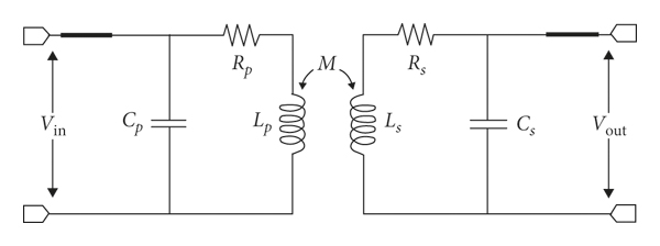
The improvement of WPT comes from better coupling coefficient k due to higher M according to

The traditional approach to improve WPT is to increase the magnetic field by increasing the self-inductance through adding more turns to the coil or increasing the length of the antenna conductor. This leads to higher induced voltage at the receiver according to Faraday law in the following equation [Reference Ho, Kim and Poon2]:
where V 2 is the induced voltage at a receiver, ω is the operating frequency, μ0 is the permeability of free space, and H is the magnetic field generated by a source at a receiver of area S. However, any misalignment can cause the loss of the flux linkage and then the reduction in WPT.
WPT for implants is established between asymmetrical antennas because the secondary implantable antenna is much smaller than the primary wearable transmitter due to the high permittivity of body tissues. An accurate position for the secondary antenna with respect to the primary one is unguaranteed during implantation, and hence, the misalignment and then a reduction in WPT efficiency can occur.
It is important to find a proper design that can provide better coupling when the receiver encounters a misaligned position. An understanding of the flux lines distribution can help in modifying this distribution to get larger flux linkage with the receiver and then a higher coupling coefficient k.
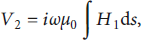
A meandered loop antenna is proposed in this paper as shown in Figure 2. The loop antenna with a perimeter of about one λ (wavelength) long behaves as a folded dipole antenna with two λ/2 dipoles. The directions of the currents along the two halves are the same as shown in Figure 3(a). The surface current along each halve will be maximal at the center and becomes weaker at the ends. These currents generate a magnetic field around the conductor in a direction following the right-hand rule. As a result, the generated fields will be in opposite directions in the center area of the conventional loop antenna and will cancel out each other. This leads to weak magnetic field at the middle area and stronger at the edges as will be seen in Sections 2 and 3.
The proposed antenna: (a) fabricated prototype and (b) detailed dimensions in mm.
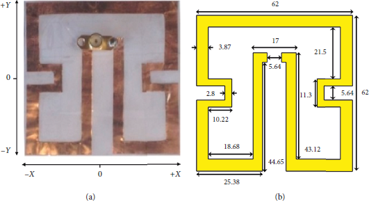
(a) Surface current distribution in a square loop antenna. (b) Surface current distribution in the proposed meandered loop antenna. (c) Magnetic field distribution for both antennas.
The magnetic field is distributed in closed lines around the source conductor. Larger induced voltage can be generated at the receiver when these lines cut the effective parts of the receiver antenna in an appropriate direction. This means that the z components of magnetic lines from the horizontal conductor along the x-axis shown in Figure 3(c) are distributed in vertical closed lines. It can induce voltage at the horizontal conductor of the receiver while it is less effective at the vertical conductors. The same scenario is true for the horizontal closed lines fields from the vertical conductor. A reshape for the generated magnetic field distribution at the target receiver is important to design an efficient WPT system.
2.1. Configuration of the Wearable Meandered Loop Antenna
Meandered loop antenna is a technique that helps in reducing the antenna size [Reference Alrawashdeh, Huang and Cao35]. The magnetic field in the internal area of the loop can be consolidated through meandering the antenna in a specific way to create a constructive combination. A redirection of the surface current is proposed in this work as shown in Figure 3(b). A strong magnetic field and redistribution to the magnetic flux can be generated in almost the whole area of the antenna. This can be achieved by dragging the exciting port into the internal area. The antenna has been meandered more at the sides to get a smaller antenna size at the same operating frequency. The new design has achieved two advantages: the first one is to generate combined magnetic fields constructively in most of the antenna area and the second is that the generated magnetic field is strong along two different axes in the xy-plane of the antenna. Currents along the two axes generate magnetic lines distribution vertically and horizontally in closed lines, and the generated field is strong in almost all antenna areas as shown in Figure 3(c). The dense orthogonal lines provide better coupling with the receiver at different locations and then improve WPT. Furthermore, it will improve the misalignment issues as will be discussed in Section 3.
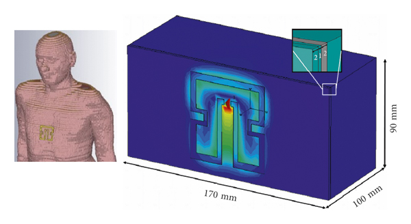
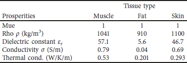
The proposed antenna covers both the MedRadio band and the ISM band of 433 MHz. This antenna is fabricated by cutting a copper sheet into shape. The thickness of the copper sheet is 0.1 mm. This thickness does not significantly affect the performance of the antenna. The simulated radiation efficiency and gain of this antenna on a body model that consists of 4 layers as shown in Figure 4 are 1.13% and −16.5 dB, respectively. The properties of these layers are defined as a biotissue from the CST Voxel family with broadband properties from 0.1 to 3 GHz as shown in Table 1. The thicknesses of these layers are 2 mm, 1 mm, 2 mm, and 95 mm for clothes, skin, fat, and muscle, respectively. These values are expected to be low due to the high energy absorption rate of the tissue. The antenna is suitable for in-body communication at the MedRadio band with an implantable antenna or for off-body communication as a repeater between the implantable antenna and an external far away reader based on the link budget [Reference Agneessens, Van Torre, Tanghe, Vermeeren, Joseph and Rogier36]. The square loop is optimized to cover the desired bands using CST software. It has dimensions of 90 mm × 90 mm with 5.4 mm strip width and 8.6 mm feeding gap.
Gustav voxel body model and a simplified body model used for the simulation.
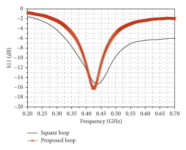
The simulated reflection coefficients of the standard square loop and the proposed meandered wearable antenna on the body model are shown in Figure 5. These antennas have been optimized to match 50 Ω using CST. The proposed loop has a narrower bandwidth due to the meandering technique as compared with the conventional loop but still has a sufficient bandwidth of 65 MHz to cover the desired bands.
The simulated reflection coefficients of the proposed meandered loop and the traditional square loop antennas on the body model.
2.2. Magnetic Field Strength
The proposed meandered loop antenna is intended to be attached to the body tissue working as a wearable antenna. The square loop and the proposed loop antennas were evaluated using CST Microwave Studio with the Gustav voxel body model and a simplified body model as shown in Figure 4. The results on both body models are found in good agreement so that the simplified body model was used in most simulations. The size of the simplified body model is chosen to be consistent with the container that is used for measurements as will be shown in Section 4.
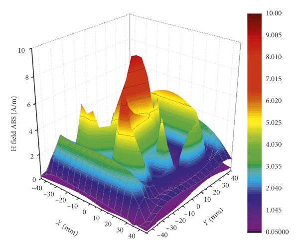
The generated magnetic field strength in the z-direction for the proposed antenna shown in Figure 5 was examined along the two major axes of the xy-plane and compared with the conventional square loop antenna as shown in Figure 6. In this figure, the field of the traditional square loop is shown in grid which is dominant mostly along the x-axis. The internal area has weak field because the field lines are combined destructively as mentioned before. However, the field still exists although weak because the conductor containing the feeding port has the highest surface current and will contribute higher field. The effect of this weakness on the coupling will be very obvious when the receiver is moved along the y-axis. In the case of the meandered loop antenna, the combined magnetic fields exist along both x- and y-axes and stronger than the conventional case as indicated by horizontal bars shown in Figure 6. It can be noticed that the middle area has the strongest field because it contains the excitation port. The field can be observed in the entire area of the antenna as compared with the traditional one which generates field mostly along the edges. This gives more flexibility and better coupling to the receiver in terms of misalignment in different directions as will be seen in Section 3.
The magnetic field strength along x and y offsets for the proposed and the square loop antennas. The square loop antenna results are indicated by grids. The results for the proposed meandered loop antenna are indicated by horizontal bars.
2.3. Specific Absorption Rate
The specific absorption rate (SAR) is an essential factor to measure the absorbed power in the tissue [Reference Rabaey, Mark and Chen1, Reference Alrawashdeh, Hunag, Kod and Sajak37]. It is primarily determined by the electric field as shown by
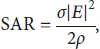
where ρ (kg/m3) is the mass density, σ (S/m) is the conductivity of the tissue, and |E| (V/m) is the electric field intensity.
The maximum transmit power to be used within the safety regulations can be computed according to this value. The FCC SAR regulation of 1.6 W/kg per 1 g averaging was considered to determine the usability of the proposed wearable antenna limits. It is found by calculating the SAR using CST Studio that the proposed design can be used with a transmission power of up to 274 mW. This power limit will be considered in the evaluation of the antenna performance in terms of WPT.
3. Misalignment Analysis between Wearable and Implantable Antennas
The misalignment issue breaks the optimum operating condition of the WPT system, and the WPT efficiency can be significantly reduced. Because of the magnetic field distribution, the proposed design shows robust performance against the misalignment issue.
To demonstrate the feasibility of the design, an implantable antenna has been optimized based on the same approach as the wearable antenna. This implantable antenna will be used as a receiver to work with the wearable antenna to measure the transmission coefficient S21 along different offset scenarios. The size of the implantable antenna is much smaller than that of the wearable antenna with a size ratio of 1 : 18.3.
3.1. Implantable Antenna
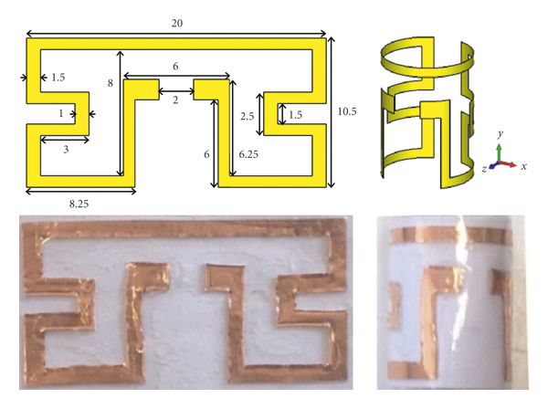
An implantable loop antenna was designed to have a structure similar to the proposed wearable antenna as shown in Figure 7. The structure was modified from the flat wearable antenna and can be bent around cylindrical implants with minimum dimensions of 11 mm in length and 3.5 mm in radius so that very little space will be occupied by the antenna. This implantable antenna shows the broadband response in both cases, flat and bent, as shown in Figure 8.
Dimensions and photographs of the fabricated implantable antenna (all dimensions in mm).
The reflection coefficient of the proposed implantable antenna in two cases of flat and bent.
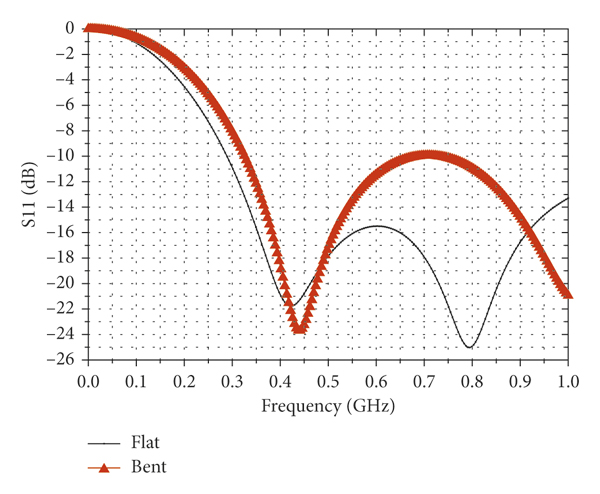
Both structures cover well the desired bands of 402–405 MHz and 433 MHz. The radiation efficiency and gain of the implantable antenna are 0.056% and −28.5 dB, respectively. These values are expected due to the high loss of body tissues and the small size of the antenna.
The implantable antenna is made of a thin copper sheet with a thickness of 0.04 mm. To prevent direct contact of the antenna material with the tissue, the implantable antenna is surrounded by a thin polypropylene adhesive tape of 0.04 mm. This thin layer has a negligible effect on the antenna performance.
3.2. Analysis of Misalignment
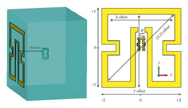
The misalignment between a pair of wearable and implantable antennas was investigated in terms of S21. The implantable antenna was inserted 30 mm in depth in the body model. It is then shifted along x, y and (x, y) offsets and rotated around the azimuth angle θ as indicated in Figure 9. The result is compared with a standard square loop pair tested in the same scenario.
The setup of testing S21 between the proposed pair of antennas.
The investigation of misalignment is shown in Figure 10. It is shown that, when the implantable antenna has an offset along the x-axis, the proposed antenna has a similar response to the square loop because both pairs have relatively strong magnetic fields along the x-axis as shown in Figure 10(a). But the magnitude of S21 is about 4 dB better as a result of the stronger magnetic field generated by the proposed meandered antenna. Along the y-axis, the effect of the new axis is very obvious. The proposed pair has an approximately stable response against offset with a better S21 of 5 dB on average as compared with the square loop as shown in Figure 10(b).
The simulated misalignment comparison between the proposed and the square loop antennas along (a) x-axis, (b) y-axis, (c) (x, y) diagonal, and (d) azimuth angle θ.
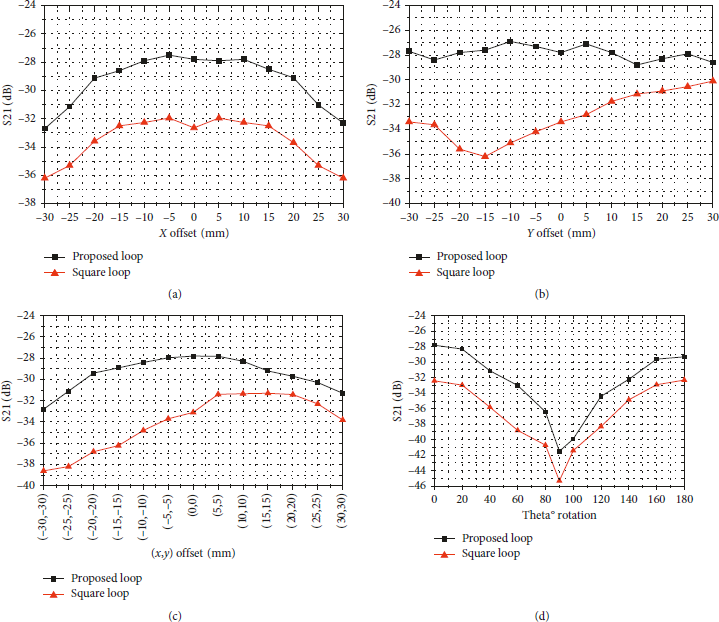
Figure 10(c) indicates the diagonal offset. The proposed pair has a more stable response compared with the square loop with an advantage of 2 dB up to 7 dB. This advantage comes from the strength of the magnetic field along both x- and y-axes so that the weak coupling from one direction can be compensated by the other direction. The location of the exciting port in the internal area adds more advantages to make the response smoother while the response in the square loop case is more biased toward the side of the exciting port. Another offset was examined by rotating the implantable antenna around the azimuth. The response of both pairs is similar, but the proposed design still has a S21 up to 4 dB better as shown in Figure 10(d).
3.3. Transmission Coefficient Measurement for the Proposed Design
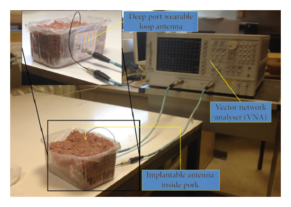
The proposed wearable and implantable antennas were fabricated and tested in minced pork that mimics human body tissues [Reference Huang, Lee, Chang, Chen, Yo and Luo9, Reference Alrawashdeh, Hunag, Kod and Sajak37]. The transmission coefficient S21 is measured to evaluate the WPT as shown in Figure 11.
The comparison of the simulated and measured efficiencies of the rectifier and measured voltages.
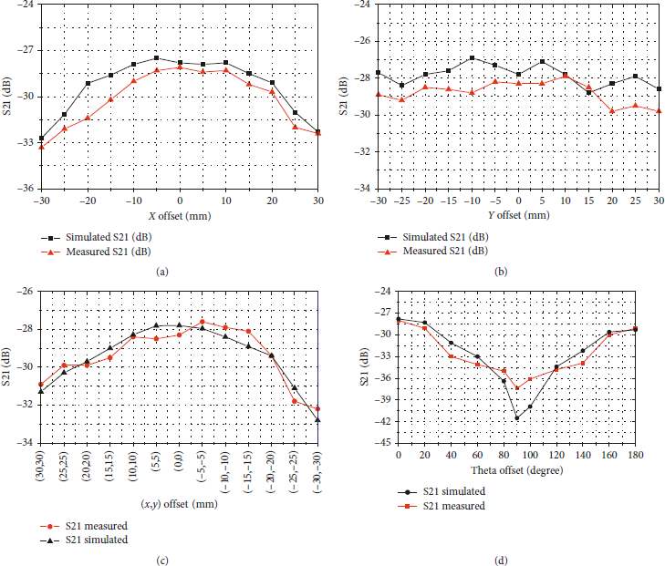
The same procedure of examining S21 mentioned in Section 3.2 was repeated. The offsets in the x-axis and y-axis directions, diagonally with (x, y) offset, and rotation around the azimuth angle θ were examined. The measured results of S21 are in good agreement with the simulated one as depicted in Figure 12. These results validate the advantage of the proposed design.
The simulated and measured transmission coefficients of the proposed pair antennas with offsets along (a) x-axis, (b) y-axis, (c) (x, y) diagonal (x, y), and (d) Theta offset.
4. Wireless Power Transmission
The WPT is investigated in terms of the real power that can be delivered to the target device using the proposed antennas. A rectifier circuit is developed and integrated with the implantable antenna to form a rectenna. The role of the rectenna is to capture the RF signal from the transmitter and convert it into DC power to be used for powering implantable devices directly or recharging a battery. The design and test of this rectifier will be explained in this section along with the analysis of the maximum power delivery within the safety limits.
4.1. The Rectifier
A rectifier circuit with a dimension of 10 mm × 5 mm was designed to be integrated with the implantable antenna. The geometry detail of the rectifier with component values is shown in Figure 13. This design is based on the principle of voltage doubler circuit using dual zero bias Schottky diodes HSMS-2822 from AVAGO Technologies [38]. The Advanced Design System software 2011.01 was used to develop the circuit. The optimization process to miniaturize this rectifier is based on reducing the size of transmission lines, and then, the overall performance of the rectifier can be compensated by tuning the values of the lumped elements.
The geometry of the designed rectifier (all dimensions in mm).
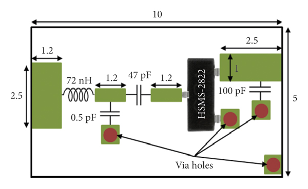
The lumped components are approximated then to realistic values, and the size of the transmission lines is slightly changed to retrieve the optimum performance of the rectifier. This process is repeated many times to get smaller rectifier until the maximum miniaturization is reached. An LC matching circuit is used to convert the input impedance of the rectifier to 50 Ω so that it can be connected directly to the antenna.
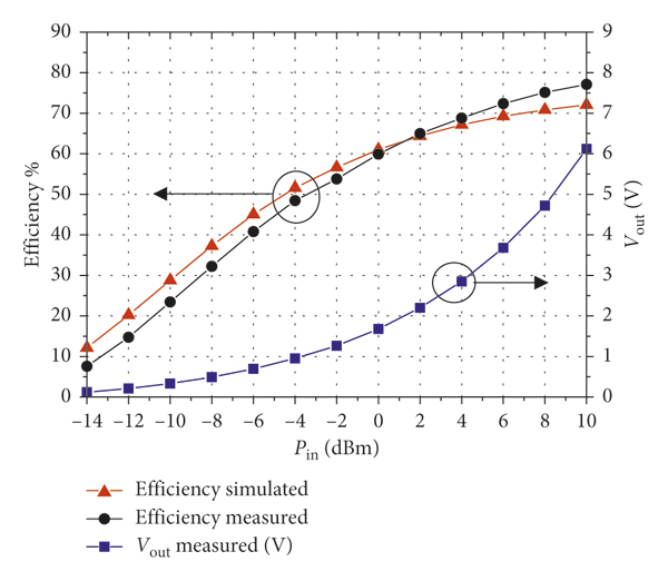
The rectifier showed the best response on a load value of 4.7 KΩ. It has an RF to DC conversion efficiencies of 28% at −10 dBm input power up to more than 70% at 10 dBm input power. This rectifier can offer more than 50% efficiency when the input power is larger than −4 dBm. The main reason for the difference in efficiency is because the impedance of the diode changes with the input power level, and hence, the efficiency of the rectifier is a function of the input power. The circuit was fabricated on a Duroid 5880 substrate with a relative dielectric constant of 2.2 and a thickness of 1.57 mm.
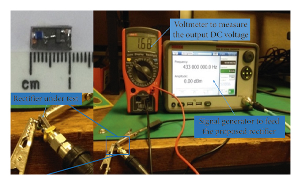
The measurement setup is shown in Figure 14. It consists of a signal generator to feed the rectifier and a multimeter to measure the voltage on the load. A range of input powers at 433 MHz has been applied to the circuit. It showed a 50% rectification efficiency with input power −4 dBm and the efficiency was increasing with the increase in the input power level until the value 10 dBm where the efficiency is saturated at around 76%. The simulated and measured efficiencies are in very good agreement as depicted in Figure 15.
The measurement setup of the proposed rectifier.
The comparison of the simulated and measured efficiencies of the rectifier and measured voltages.
4.2. Maximum Power Delivery
Limit is tested using the wearable antenna and implantable rectenna. First, the proposed design was tested under a low input power of 10 mW to demonstrate the ability of the system in delivering sufficient power to the load. The experiment setup contains a signal generator, a cubic container with dimensions 9 cm × 10 cm × 17 cm filled with minced pork to mimic body tissue, and a voltmeter to measure the voltage as shown in Figure 16(a). A 50 Ω coaxial cable is used to connect the implantable antenna to the rectifier. It is worth mentioning that the coaxial cable has no effect on the coupling strength where a bead had been added on the connector. The measurement was not significantly changed by these efforts. With 10 mW input power available to the wearable antenna, the received power at the load was 13 μW.
The experiment setup of measuring the output power versus different input power: (a) with a constant input power of 10 dBm and (b) with a sweep of input power.
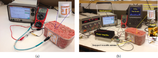
A power amplifier was used to boost the level of the transmit power up to 274 mW as shown in Figure 16(b). Both the output DC voltage and the power are measured against a range of input power not exceeding the safety limit according to the SAR as shown in Figure 17. The total power transfer efficiency is defined by
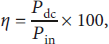
where η is the total wireless power transfer efficiency including RF to RF and RF to DC conversion efficiencies. P dc and P in are the power delivered to the load and the power available to the transmitting wearable antenna, respectively.
The measured output power and voltage as a function of the input power.
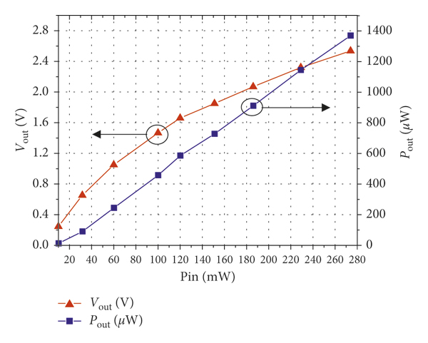
These results indicate a total power transfer efficiency of 0.1 % when the power available to the wearable antenna is 10 mW. The efficiency is relatively low mainly because of the low RF to RF transfer efficiency due to the high tissue loss. The efficiency can be increased up to 0.5% when the available power exceeded 50 mW.
A DC power of more than 1000 μW can be harvested with an input power under safety limits. The received power is enough to power many common implantable medical devices such as a pacemaker, a nerve stimulation device, and a glucose measurement system that requires 70 μW [Reference Das and Yoo39], 100 μW [Reference Niu, Hao, Li, Ma and Wu40], and 48 μW [Reference Bazaka and Jacob41] power, respectively.
5. Conclusion
This paper presents a novel approach to design a meandered loop antenna that generates strong magnetic fields along two orthogonal axes. The new design shows significant advantages in terms of improving WPT and the robustness to the misalignment issue.
Two meandered loop antennas are designed based on the same approach to form a pair of compatible wearable and implantable antennas. The proposed pair was compared with a pair of conventional square loop antennas. The new design showed very good tolerance against the misalignment in different directions and better power transmission. Then a rectifier circuit of the size of 10 mm × 5 mm was designed and optimized to be used with the implantable antenna to form a rectenna. The rectenna works with the wearable antenna as a WPT system. This rectifier performs RF to DC conversion with an efficiency of 50% to 70% at the input power from −4 dBm to 10 dBm.
The measured results validated the simulated one. The overall results demonstrated the significant advantages of the proposed design. The output DC voltage and power with respect to different inputs within the safety limits were measured. A DC power of more than 1000 μW can be harvested under the condition that the transmitted power by the wearable antenna is under safety limits. This amount of power is more than enough to directly power many common implantable medical devices including the pacemaker, the nerve stimulation device, and the glucose measurement system.
Data Availability
The data used to support the findings of this study can be available upon request.
Conflicts of Interest
The authors declare that they have no conflicts of interest.
Acknowledgments
This work was supported by Interdisciplinary Network Fund Grant, UK, and the Higher Committee for Education Development (HCED), Iraq, under Sponsorship D-10/66.


 Open access