

1. INTRODUCTION
The Global Navigation Satellite System (GNSS) alone does not always provide adequate performance, particularly in demanding air vehicle applications where high levels of integrity are required. For an avionics navigation system, integrity directly relates to the level of confidence that can be placed in the information provided by the on board system. It includes the ability of the navigation system to provide timely and valid warnings to users when the system must not be used for the intended operation or phase of flight. Specifically, an avionics navigation system is required to deliver an alert of any malfunction (as a result of a set alert threshold being exceeded) to users within a given period of time. Time-to-Alert (TTA) is defined as the maximum time allowed from the moment a fault resulting in an unsafe condition is detected to the moment that the user is made aware of it (Ochieng et al., Reference Ochieng, Sauer, Walsh, Brodin, Griffn and Denney2003). Integrity risk, also referred to as the probability of misleading information, is defined as the probability that the navigation positioning error exceeds the alert limit and that the event is not detected. Loss of integrity can happen in one of two ways. Either an unsafe condition is not detected, or it is detected but the alert is not received by the user within the required TTA. The alert limit defines the largest position error, which results in a safe operation. This is specified such that the error can degrade to a level larger than the 95th percentile accuracy requirement but still within a safe limit. GNSS augmentation can take many forms but all share the same fundamental principle of providing supplementary information whose objective is to improve the performance and/or trustworthiness of the system. GNSS augmentation benefits in the aviation domain can be summarized as follows:
• Increased runway access, more direct en-route flight paths and new precision approach services;
• Reduced and simplified avionics equipment;
• Potential elimination of some ground-based navigation aids (VOR, ILS, etc.) with cost saving to Air Navigation Service Providers (ANSPs).
In addition to the existing Space- and Ground-Based Augmentation Systems (SBAS and GBAS), GNSS augmentation may take the form of additional information being provided by other on board avionics systems. As these systems normally operate via separate principles to the GNSS, they are not subject to the same sources of error or interference. A system such as this is referred to as an Aircraft-Based Augmentation System (ABAS), (ICAO, 2005). ABAS is different to Receiver Autonomous Integrity Monitoring (RAIM), in which the aircraft characteristics (flight dynamics, body shape, antenna location, electromagnetic compatibility/interference, etc.) are not considered. The remainder of the paper is arranged as follows: Section 2 specifies the Avionics-Based Integrity Augmentation (ABIA) architecture and definitions, Section 3 describes ABIA Integrity Flag Generator (IFG) development and Section 4 presents the Conclusions. Part 2 of the paper (published separately) provides the ABIA integrity flag threshold criteria and a detailed TORNADO-IDS (Interdiction and Strike variant) simulation case study.
2. ABIA ARCHITECTURE AND DEFINITIONS
As a result of extensive research and flight test activities performed with GPS-based Time and Space Position Information (TSPI) systems on TORNADO-Interdiction and Strike (IDS), TYPHOON, MB-339CD and other aircraft (Sabatini and Palmerini, Reference Sabatini and Palmerini2008), an ABAS concept was developed by CSV-RSV specifically targeting GNSS integrity augmentation in TSPI applications (Figure 1). In this TSPI Avionics-Based Integrity Augmentation (T-ABIA) system, the aircraft sensors provide information on the aircraft's relevant flight parameters (navigation data, engine settings, etc.) to an Integrity Flag Generator (IFG), which is also connected to the on board GNSS. The IFG can be incorporated into one of the existing airborne computers or can be a dedicated processing unit. Using the available data on GNSS and the aircraft flight parameters, integrity signals are generated which can be displayed on one of the cockpit displays and/or sent to an Aural Warning Generator (AWG).
T-ABIA system for flight test applications.

Various modelling, simulation and flight test activities were performed to develop this novel T-ABIA system (Sabatini and Palmerini, Reference Sabatini and Palmerini2008), demonstrating the validity of the concept and its technical feasibility. The next logical step was to extend the results obtained with this prototype to the design of a more advanced ABIA system suitable for manned and unmanned aircraft applications (both civil and military). Such a system can provide steering information to the pilot (as the T-ABIA) and, additionally, electronic commands to the aircraft/Unmanned Aerial Vehicle (UAV) Flight Control System (FCS), allowing for real-time and continuous integrity monitoring, avoidance of safety-/mission-critical flight conditions and rapid recovery of the Required Navigation Performance (RNP) in case of GNSS data degradation or loss. The architecture of this advanced ABIA system is depicted in Figure 2.
ABIA architecture evolution for manned and unmanned aerial vehicles.

The systems described above address both the predictive and reactive nature of GNSS integrity augmentation. To understand this concept, let us first of all introduce some key definitions of alerts and TTAs applicable to the ABIA system.
• Caution Integrity Flag (CIF): a predictive annunciation that the GNSS data delivered to the avionics system is going to exceed the RNP thresholds specified for the current and planned flight operational tasks (GNSS alert status).
• Warning Integrity Flag (WIF): a reactive annunciation that the GNSS data delivered to the avionics system has exceeded the RNP thresholds specified for the current flight operational task (GNSS fault status).
• ABIA Time-to-Caution (TTC): the minimum time allowed for the caution flag to be provided to the user before the onset of a GNSS fault resulting in an unsafe condition.
• ABIA Time-to-Warning (TTW): the maximum time allowed from the moment a GNSS fault resulting in an unsafe condition is detected to the moment that the ABIA system provides a warning flag to the user.
Based on the above definitions, we can define two separate models for the time responses associated to the Prediction-Avoidance (PA) and Reaction-Correction (RC) functions performed by the ABIA system (Figure 3). The PA time response is given by:
 $${\rm \Delta} T_{PA} = {\rm \Delta} T_{Predict} + {\rm \Delta} T_{C - Report} + {\rm \Delta} T_{Avoid} $$
where:
- ΔT Predict
=time required to predict a critical condition.
- ΔT C−Report
=time required to communicate the predicted failure to the FPG module.
- ΔT Avoid
=time required to perform the avoidance manoeuvre.
In this case, we have ΔT Avoid≤TTC. If the available avoidance time ΔT Avoid is not sufficient to perform an adequate avoidance manoeuvre (i.e., ΔT Avoid>TTC), the aircraft will inevitably encroach on critical conditions causing GNSS data losses or unacceptable accuracy degradations. In this case, the RC time response applies:
 $${\rm \Delta} T_{RC} = {\rm \Delta} T_{Detect} + {\rm \Delta} T_{W - Report} + {\rm \Delta} T_{Correct} $$
where:
- ΔT Detect
=is the time required to detect a critical condition.
- ΔT W−Report
=is the time required to communicate the failure to the FPG module.
- ΔTcorrect
=is the time required to perform the correction manoeuvre.
In general, we must have ΔTDetect+ΔTW−Report≤TTW. The RC time response is substantially equivalent to that which existing GBAS and SBAS systems are capable of achieving. A comparison between Figure 3(a) and (b) allows the reader to immediately visualise the benefits introduced by the ABIA PA function. Further progress is possible by adopting a suitable algorithm in the IFG module capable of initiating an early correction manoeuvre as soon as the condition ΔT Avoid≤TTC is violated. In this case, the direct Prediction-Correction (PC) time response would be:
 $${\rm \Delta} T_{PC} = {\rm \Delta} T_{Predict} + {\rm \Delta} T_{C - Report} + {\rm \Delta} T_{Erarly\; Correct} $$
where T Early Correct is the time required to perform an early correction manoeuvre.
ABIA PA and RC functions representation.

This concept is illustrated in Figure 4. By comparison with Figure 2, it is evident that the ABIA system would be able to reduce the time required to recover from critical conditions if the following inequality is verified:
 $$\Delta T_{Early\; Correct} \lt \; TTC + \Delta T_{Detect} + \Delta T_{C - Report} + \Delta T_{Correct} $$
ABIA PC function representation.

3. ABIA IFG DEVELOPMENT
As a first step, a dedicated analysis is required in order to determine the flight envelope limitations associated with the use of GNSS. By analysis, simulation and flight test the following models are obtained:
• The Antenna Obscuration Matrices (AOM) in azimuth and elevation, constructed as a function of attitude (Euler) angles in all relevant aircraft configurations;
• The GNSS Carrier-to-Noise and Jamming-to-Signal Models (CJM), accounting for the relevant transmitter/receiver characteristics, propagation losses and interference;
• The Multipath Signal Model (MSM) including fuselage, wing and ground path fading components and the associated range errors;
• The Doppler Shift Model (DSM) and associated critical conditions causing GNSS tracking issues.
Using appropriate aircraft dynamics models, the manoeuvring envelope of the aircraft is determined in all required flight conditions. Using the AOM, CJM, MSM and DSM models, together with the GNSS receiver tracking models and the manoeuvring requirements of specific flight tasks (e.g., test/training missions or standard airport approach procedures), it is possible to identify the conditions that are potentially critical for the on board GNSS system and set appropriate thresholds for the ABIA CIFs and WIFs, thereby generating timely alerts when the aircraft is performing critical manoeuvres prone to induce GNSS signal outages. Once the reliability of the mathematical algorithms is established, the ABIA IFG module is implemented in the aircraft to alert the pilot when the critical conditions for GNSS signal losses are likely to occur.
3.1. IFG Module Architecture
Figure 5 shows the architecture of an ABIA IFG module and its interfaces. This module is designed to provide CIF and WIF alerts in real-time (i.e., in accordance with the specified TTC and TTW requirements in all relevant flight phases). IFG module inputs are from the GNSS receiver and other aircraft sensors. The GNSS and Sensors Layer (GSL) passes the aircraft Position, Velocity, Time (PVT) and attitude (Euler angles) data (from the on board Inertial Navigation Systems, Air Data Computer, etc.), GNSS data (raw measurements and PVT) and the Flight Control System (FCS) actuators data to the Data Extraction Layer (DEL). At this stage, the required Navigation and Flight Dynamics (NFD) and GNSS Constellation Data (GCD) are extracted, together with the relevant information from an aircraft Three-Dimensional Model (3DM) and from a Terrain and Objects Database (TOD). The 3DM database is a detailed geometric model of the aircraft built in a Computer Aided Three-dimensional Interactive Application (CATIA). The TOD uses a Digital Terrain Elevation Database (DTED) and additional man-made objects data to obtain a detailed map of the surfaces neighbouring the aircraft.
IFG module architecture.

In the Integrity Processing Layer (IPL) the Doppler Analysis Module (DAM) calculates the Doppler shift by processing the NFD and GCD inputs. The Multipath Analysis Module (MAM) processes the 3DM, TOD, GNSS Constellation Simulator (GCS) and A/C Navigation/Dynamics Simulator (ADS) inputs to determine multipath contributions from the aircraft (wings/fuselage) and from the terrain/objects close to the aircraft. The Obscuration Analysis Module (OAM) receives inputs from the 3DM, GCS and ADS, and computes the GNSS antenna(e) obscuration matrices corresponding to the various aircraft manoeuvres. The Signal Analysis Module (SAM) calculates the link budget of the direct GNSS signals received by the aircraft in the presence of atmospheric propagation disturbances Carrier-to-Noise (C/N0), as well as the applicable Radio Frequency (RF) interference (Jamming-to Signal [J/S]) levels. The Integrity Flags Layer (IFL) uses a set of predefined CIF/WIF threshold parameters to trigger the generation of both caution and warning flags associated with antenna obscuration, Doppler shift, multipath, carrier, interference and satellite geometry degradations.
3.2. Antenna Obscuration Analysis
Due to the manoeuvres of the aircraft, the wings, tail and fuselage will obscure some satellites during the flight. Figure 6 shows the structure of the OAM.
GNSS antenna obscuration analysis.

A Three Degrees of Freedom (3-DOF) model with variable mass was developed to calculate the trajectory of the aircraft (i.e., position, velocity and attitude (Euler angles)) during the different flight phases. Taking into account the aircraft shape (CATIA 3-D model), the aircraft flight dynamics (pitch, roll and yaw variations) and the geometric displacement of the GNSS satellites in view, the Antenna Obscuration Matrices (AOM) are generated for the different flight conditions. An example of the TORNAO-IDS AOM obtained with 50° bank angle is shown in Figure 7.
TORNADO-IDS upper antenna (centrally mounted) AOM (Bank=+50°).

Besides the AOM, other factors influence the satellite visibility. In general, a satellite is geometrically visible to the GNSS receiver only if its elevation in the antenna frame is above the Earth horizon and the antenna elevation mask. It should be noted that even high performance avionics GNSS antennae have gain patterns that are typically below -3 dB at about 5 degrees elevation and, as a consequence, their performance becomes marginal below this limit (Figure 8).
High quality antenna gain pattern (L1 frequency).

In order to determine if a satellite is obscured, the Line of Sight (LOS) of the satellite with respect to the antenna phase centre has to be determined. To calculate the satellite azimuth and elevation with respect to the antenna a transformation matrix between the Earth Centred Earth Fixed (ECEF) and antenna frames must be applied. This is obtained from:
 $${\rm T}_{\rm E}^{\rm a} = {\rm T}_{\rm b}^{\rm a} *{\rm T}_{\rm N}^{\rm b} *{\rm T}_{\rm E}^{\rm N} $$
where:
- Tba
is the transformation matrix between the aircraft body frame and the antenna frame,
- TNb
is the transformation matrix from the East-North-Up (ENU) frame to body frame and
- TEN
is the ECEF to ENU transformation matrix.
As an example, Figure 9 shows the trajectory of an aircraft during a Turning Descent Manoeuvre (TDM) lasting 300 seconds.
Turning descent manoeuvre.

Figure 10 shows the combined Global Positioning System (GPS)/GALILEO satellite visibility during the same flight phase. During the manoeuvre, the number of satellites in view varies from 7 to 16.
Satellite Visibility (TDM).

TORNADO-IDS flight trials showed that the signal losses due to antenna obscuration can be reduced by introducing constraints to the aircraft initial heading for left and right turns (Sabatini and Palmerini, Reference Sabatini and Palmerini2008). In particular, it was found that the satellite losses are minimised by reducing the number of left turns performed with the initial heading ranging from North-East to South-East, and the number of right turns performed with the initial heading between South-West and North-West. This fact can be explained by considering a typical northern hemisphere mid-latitude sky plot shown in Figure 11.
GPS sky-plot (northern hemisphere mid-latitude).
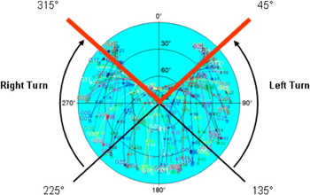
Since in the northern hemisphere/mid-latitudes the majority of satellites are available in the azimuth range 45 to 315 degrees, a left turn with an initial heading in the range 45 to 135 degrees would be prone to GPS data losses, due to the reduced number of satellites available in the direction of the turn. Similar considerations apply for right turns performed with an initial heading in the range 225 to 315 degrees.
3.3. GNSS Signal and Interference Analysis
The received signal strength is affected by a number of factors including transmitter and receiver characteristics, propagation losses and interferences. In our case, the SAM combines the various factors contributing to the GNSS link budget and signal degradations due to interference. Multipath induced effects are considered separately. The SAM module takes inputs from the GCS and NFD modules, and computes both C/N0 and J/S. The ratio of total carrier power to noise C/N0) in dB-Hz is the most generic representation of received signal strength. This is given by:
 $$\displaystyle{{\rm C} \over {{\rm N}_0}} = {\rm P}_{\rm t} + {\rm G}_{\rm t} + {\rm G}_{\rm r} + {\rm L}_{\rm s} - {\rm L}_{\rm a} - {\rm L}_{\rm r} - \sigma _{\rm m} - {\rm N}_{\rm f} $$
where:
- PT
is the transmitted power level (dBw);
- Gt
is the satellite antenna gain (dBic);
- Gr
is the receiver antenna gain toward the satellite (dBic);
- Ls
is the free space loss (dB);
- La
is the atmospheric attenuation in dry-air (dB);
- Lr
is the rainfall attenuation (dB);
- σ m
is the tropospheric fading (dB) and;
- Nf
is the receiver noise figure (dB).
The link budget calculated from Equation (6) only refers to the direct GNSS signal received from a satellite. Multipath effects, which are due to the geometric and reflective characteristics of the environment surrounding the GNSS antenna are not included in this calculation and are discussed separately. The L-band antenna onboard GPS satellites is designed to radiate the composite L-band signals to the users on and near the Earth. As shown in Figure 12, the GPS satellite viewing angle from edge-to-edge of the Earth is about 27·7° (Boithias, Reference Boithias1982). The satellite antenna is designed to illuminate the Earth's surface with an almost uniform signal strength. The path loss of the signal is a function of the distance from the antenna phase centre to the surface of the Earth. The path loss is least when the satellite is directly overhead and is most at the edge of the coverage area.
GPS Satellite Antenna Coverage.

The difference in signal strength caused by this variation in path length is about 2·1 dB [6] and the satellite antenna gain can be approximated by:
 $${\rm G}_{\rm t} = 2{\cdot}5413*\sin {\rm E} - 2{\cdot}5413$$
where E is the elevation angle. Similarly, the avionics antenna gain pattern shown in Figure 8 can be approximated by:
 $${\rm G}_{\rm r} = 9\cdot8756*\sin {\rm E} - 4\cdot7567$$
GNSS signal frequencies (L-band) are sufficiently high to keep the ionospheric delay effects relatively small. On the other hand, they are not so high as to suffer severe propagation losses even in rainy conditions. However, the atmosphere causes small but non-negligible effects that must be taken into account. The major effects that the atmosphere has on GNSS signals include those detailed in (Parkinson and Spilker, Reference Parkinson and Spilker1996):
• Ionospheric group delay/carrier phase advance;
• Tropospheric group delay;
• Ionospheric scintillation;
• Tropospheric attenuation;
• Tropospheric scintillation.
The first two effects have a significant impact on GNSS data accuracy but do not directly affect the received signal strength (C/N0). Ionospheric scintillation is due to irregularities in the electron density of the Earth's ionosphere (scale size from hundreds of metres to kilometres), producing a variety of local diffraction and refraction effects. These effects cause short-term signal fading which can severely stress the tracking capabilities of a GNSS receiver. Signal enhancements can also occur for very short periods, but these are not really useful from the GNSS receiver perspective. Atmospheric scintillation effects are more significant in the equatorial and sub-equatorial regions and tend to be less of a factor at European and North-American latitudes. Unfortunately, at the moment, there is little we can do to estimate ionospheric scintillation effects and no efficient algorithms are available for integration in the ABIA system. Tropospheric attenuation in the GNSS frequency bands is dominated by oxygen and the effects of other chemical species can be neglected for most applications. Oxygen attenuation (A) is in the order of 0·035 dB for a satellite at zenith and its variation with elevation angle (E) can be approximated by (Parkinson and Spilker, Reference Parkinson and Spilker1996):
 $${\rm A(E)} \cong \displaystyle{{0{\cdot}07} \over {\sin {\rm E} + 0{\cdot}043}}\; (\rm dB) \quad {\rm for}\; 3 \lt E \lt 10\; {deg} $$
 $${\rm A(E)} \cong \displaystyle{{0{\cdot}035} \over {\sin {\rm E}}}\; (\rm dB) \quad {\rm for} \ {\bf E} \lt 10\; {deg} $$
These formulae provide acceptable results only if E>3 degrees. However, since several other errors affect measurements from satellites with elevations below 5°, a software mask is typically employed in avionics GNSS receivers to exclude these satellites form the navigation computations (Sabatini and Palmerini, Reference Sabatini and Palmerini2008). Tropospheric rainfall attenuation has a minor effect in the GNSS frequency bands. For instance, at a frequency of 2 GHz the attenuation for high rainfall rates is less than 0·01 dB/km (rainfall attenuation below 2 GHz is even less). Tropospheric scintillation is caused by irregularities (primarily turbulence) causing variations of the refractive index. This effect varies with time, frequency and elevation angle. For small omnidirectional antennas, such as GNSS antennas, the CCIR provided the following expression for the long-term rms amplitude scintillation (Boithias, Reference Boithias1982):
 $${\rm \sigma} _{\rm m} = 0{\cdot}025{\rm f}^{0{\cdot}58} (\csc {\bf E})^{ - 0{\cdot}85} {\rm \;} \quad ({\rm dB})$$
where f is the frequency in GHz.
The Noise Figure (Nf) is related to the system noise temperature (Tsys) in Kelvin as follows (Davenport and Root, Reference Davenport and Root1987):
 $${\rm N}_{\rm f} = 10\log \left( {1 + \displaystyle{{{\rm T}_{{\rm sys}}} \over {{\rm T}_0}}} \right)\quad ({\rm db})$$
where T0=290 K=24·6 dB-K.
Tsys for antenna plus receiver can be computed using the Friis formula (Friis, Reference Friis1944). Typical Nf values for state-of-the-art GPS receivers are between 2 and 4 dB. Intentional and unintentional RF interference (jamming) can result in degraded navigation accuracy or complete loss of the GNSS receiver tracking. Jammers can be classified into three broad categories: Narrowband Jammers (NBJ), Spread Spectrum Jammers (SSJ) and Wideband Gaussian Jammers (WGJ). Fortunately, a number of effective jamming detection and anti-jamming (filtering and suppression) techniques have been developed for military GNSS applications and some of them are now available for civil use as well (Ward, Reference Ward1994). The J/S performance of a GNSS receiver at its tracking threshold can be evaluated by the following equation (Kaplan and Hegarty, Reference Kaplan and Hegarty2006):
 $$\displaystyle{{\rm J} \over {\rm S}} = 10\log {\rm QR}_{\rm c} \left[ {\displaystyle{1 \over {10^{0.1({\rm C}/{\rm N}_0 )_{{\rm MIN}}}}} - \displaystyle{1 \over {10^{0.1({\rm C}/{\rm N}_0 )}}}} \right]$$
where:
- Q
is the processing gain adjustment factor (1 for NBJ, 1·5 for SSJ and 2 for WGJ);
- Rc
is the code chipping rate (chips/s); $({\textstyle{{\rm C} \over {{\rm N}_0}}} )_{{\rm MIN}} $$
is the receiver tracking threshold (dB-Hz).

Since the weak limit in an avionics receiver is the carrier tracking loop threshold (typically the Phase Lock Loop [PLL]), this threshold is usually substituted for  $({\textstyle{{\rm C} \over {{\rm N}_0}}} )_{{\rm MIN}} $. During the flight test activities performed on TORNADO-IDS with unaided C/A code avionics receivers, it was found that in all the dynamics conditions explored and in the absence of jamming, a $({\textstyle{{\rm C} \over {{\rm N}_0}}} )$ of 25 dB-Hz was sufficient to keep tracking the satellites. As an example, using this 25 dB-Hz tracking threshold, we can calculate the J/S performance of the TORNDO-IDS GPS receiver considering one of the satellites tracked during the descent manoeuvre illustrated in Figure 9. As shown in Figure 13, during this manoeuvre, the C/N0 for Pseudo Random Noise (PRN) PRN-14 was about 37 dB-Hz.
Calculated C/N0 for PRN-14.

Table 1 shows the corresponding J/S calculations, assuming (C/No)MIN=25 dB-Hz. Using these J/S values, the minimum range in metres from a jamming source can be calculated from:
 $${\rm R}_{{\rm min}} = \displaystyle{{\lambda _j} \over {4\pi}} \left( {10^{\textstyle{{{\rm ERP}_{{\rm tj}} - {\rm P}_{{\rm rj}} + {\rm G}_{{\rm rj}} - {\rm L}_{{\rm rf}}} \over {20}}}} \right)$$
where:
- ERPtj
is the effective radiated power of the jammer (dBw).
- j
is the wavelength of jammer frequency (m).
- Prj
is the received (incident) jamming power level at threshold=
${\textstyle{{\rm J} \over {\rm S}}}$+Prs (dBw).- Prs
is the minimum received (incident) signal power (dBw).
- Grj
is the GNSS antenna gain toward jammer (dBic).
- Lrf
is the jammer power attenuation due to receiver front-end filtering (dB).

3.4. Doppler Shift Analysis
Doppler shift is the change in frequency of the received signal that is experienced when the observer (aircraft) moves relative to the signal source (satellite). The Doppler shift of the nth satellite signal frequency is given by:
 $${\rm \Delta f}_n = {\rm f}\left( {\displaystyle{{{\rm v}_{\rm i} - {\rm v}_{\rm u}} \over {\rm c}}} \right)\cos \alpha _{\rm n} $$
where:
- vi
is the satellite velocity.
- vu
is the aircraft velocity.
- c
is the speed of light.
- f
is the GNSS signal frequency.
- α n
is the angle between the aircraft velocity and the nth satellite LOS vector.
During the initial phases of the GPS-TSPI flight test campaign (Sabatini and Palmerini, Reference Sabatini and Palmerini2008), it was noted that, even in high dynamics avionics receivers, the reacquisition time after loss of one or more satellite signals could be up to 40 seconds, depending on flight conditions and satellite constellations (Figure 14). Therefore, we investigated how the Doppler shift could affect the receiver's capability to track the carrier phase and rapidly reacquire the signal after a loss. Doppler shift directly affects the signal acquisition time of the receiver, both in terms of frequency of the code and frequency of the carrier. In general, acquisition time increases in the presence of Doppler shift. Considering the case of one satellite tracked, the Doppler shift is due to the relative velocity of the satellite and the receiver (i.e., the difference between the projections of the velocity vectors along the satellite-receiver direction). The worst case is, therefore, that of an aircraft flying along the LOS to the satellite, in which the full velocity vector of the aircraft must be used to determine the relative velocity. Analysis of receiver data recorded during several flights and up to speeds of 500 knots highlighted that the Doppler effect causes a frequency shift, with respect to the carrier frequency L1, which reaches a maximum value of about 15 KHz. This value is low if compared with the GPS signal bandwidth and the high dynamic characteristics of the carrier tracking loops internal to the avionics receiver guarantee that neither the data accuracy is degraded nor the carrier phase is lost because of Doppler shift. Nevertheless, the coupling between such a frequency shift and the signal reacquisition strategy of the receiver can significantly affect the time necessary to get data after a signal loss, even when a good satellite configuration is available.
Doppler shift and signal acquisition in an avionics receiver.

J/S calculations for 25 dB-Hz tracking threshold.
3.5. Multipath Analysis
Multipath is caused by the interference of multiple reflections (from the ground and the aircraft structure) with the direct signal transmitted by the satellite, and represents a major source of error in GNSS observations. The level and characteristics of multipath depend on the geometry of the environment surrounding the antenna, the reflectivity of nearby objects/terrain and the satellite elevation angle. In order to build a reliable multipath model, a combination of signal analysis and geometric ray-tracing methods was adopted. To start, we use the aircraft 3D CATIA model to identify the geometric characteristics of the multipath signal and study the Signal-to-Noise ratio variations in the presence of multipath (S/Nm).
From Figure 15, the S/Nm and phase error for a single refection can be represented as a function of direct and multipath signal amplitudes and the multipath relative phase is β (Ward, Reference Ward1994):
 $$\displaystyle{{\rm S} \over {{\rm N}_{\rm m}}} = {\rm A}_{\rm c}^2 = {\rm A}_{\rm d}^2 + {\rm A}_{\rm m}^2 + 2{\rm A}_{\rm d} {\rm A}_{\rm m} \cos \beta $$
 $$\tan (\delta _\phi ) = \displaystyle{{{\rm A}_{\rm m} \sin \beta} \over {{\rm A}_{\rm d} + {\rm A}_{\rm m} \cos \beta}} $$
where:
- Ad
is the direct signal amplitude.
- Am
is the multipath signal amplitude.
- β
is the phase of the multipath.
Figure 16 shows that both the multipath phase β and the multipath amplitude affect the received signal. Therefore, we require a multipath model to simulate these two factors, considering the reflections from the airframe and from the ground. In our research, we adopted the Aeronautical Multipath Channel (AMC) model developed during the ESA-SDS research (Steingass, Reference Steingass2004).
Phase of GNSS signal.

Variation of Ac as function of the angle β.

Figure 17 illustrates the overall structure of the AMC model. Let h(t, τ) be the impulse response of the multipath channel model. Then h(t, τ) is given by (Steingass, Reference Steingass2004):
 $${\rm h(}t,\tau {\rm )} = 1 + \mathop \sum \limits_{{\rm i} = 1}^3 \sqrt {{\rm P}_{\rm i}} *{\rm n}_{\rm i} (t)*\delta ({\rm t} - \tau _{\rm i} )$$
AMC model structure.

where:
Pi is the Echo Power of the ith path.
The signal ni(t) is a noise signal with Power i, and a power spectral density N(f):
 $${\rm N(\,f)} = \left\{ {\matrix{ {0\;} & {{\bf f} \lt - \displaystyle{B \over 2}} \hfill \cr {\displaystyle{1 \over {\rm B}}\;} & { - \displaystyle{{\rm B} \over 2} \lt f \lt - \displaystyle{B \over 2}}\hfill \cr 0& {{\bf f} \gt - \displaystyle{B \over 2}} \hfill \cr}} \right.$$
where B is the noise bandwidth.
From the multipath channel model in Figure 18, the wing reflection, the fuselage reflection and the ground-echo are the main components of the multipath signal.
Geometric reflection model.

Figure 18 shows the geometric reflection model. The incoming wave is emitted from point T, R is the receiver location and S is the reflection point. V is a defined point on the reflecting surface and n stands for a unit vector normal to the surface.
In ray-tracing, the reflection point S and the defined point V should satisfy the equation:
 $$({\rm S} - {\rm V}) \times {\rm n} = 0$$
and the line equation connecting T and Rimage:
 $${\rm S} = {\rm T} + {\rm t} \times ({\rm R}_{{\rm image}} - {\rm T})$$
where t is a parameter between 0 and 1.
Combining Equations (20) and (21):
 $${\rm S} = {\rm T} + \displaystyle{{{\rm n} \times {\rm V} - {\rm n} \times {\rm T}} \over {{\rm n} \times ({\rm R}_{{\rm image}} - {\rm T})}}({\rm R}_{{\rm image}} - {\rm T})$$
The corresponding extra path length LmS, due to specular reflection, is then:
 $${\rm L}_{{\rm mS}} = \left| {{\rm T} - {\rm S}} \right| + \left| {{\rm R} - {\rm S}} \right| - \left| {{\rm T} - {\rm R}} \right|$$
In our wing reflection model, the wing is assumed to be flat. By Gaussian Doppler Spectrum theory, the power of the wing echo spectrum is assumed to be (Braasch, Reference Braasch1992):
 $${\rm P}_{{\rm Gr}({\rm dB})} = 20{\rm *log}\left( {\displaystyle{1 \over {\sqrt {2{\rm \pi \sigma} ^2}}} {\rm *e}^{ - {\textstyle{{{\rm f}^2} \over {2{\rm \sigma} ^2}}}}} \right)$$
where the deviation σ=3·8 Hz.
The wing reflection signal delay can be calculated from:
 $${\rm \tau} _{{\rm wing}} ({\rm t}) = \displaystyle{{2{\rm *L*sin}({\rm E})} \over {{\rm C}_0}} $$
where:
- L
is the antenna height from the wing.
- E
is the elevation angle (degrees).
- C0
is the speed of light.
The fuselage is assumed to be a cylinder and the power of the fuselage echo spectrum is given by:
 $${\rm P}_{{\rm proc}} ({\rm dB}) = 20{\rm *log}_{10} \left[ {k_1 *e^{(k_2 *|f|\; )} - SNR - k_3} \right]$$
where k1, k2 and k3 are the fuselage geometric coefficients described in (Steingass and Lehner, Reference Steingass and Lehner2004).
Previous research showed that the fuselage reflection characteristics change very little by increasing the fuselage radius. For easier implementation of the fuselage reflection model, a 2-dimensional polynomial function of 4th order was fitted to each parameter (mean, b2, b3). As an example, considering the TORNADO-IDS upper antenna located on the fuselage at a height of Lfuselage=0·05 metres, the fuselage reflection time delay is τ fuselage=1·7×10−10 s. Ground reflection becomes important only during the landing phase, when the aircraft is in close proximity of the terrain. As before, assuming a Gaussian distributed ground reflection amplitude with zero mean, the ground-echo power can be described by Equation (24). Assuming that the terrain is flat:
 $$\tau _{{\rm ground}} ({\rm t}) = \displaystyle{{2*{\rm h}*\sin ({\rm E})} \over {{\rm C}_0}} $$
where:
- h
is the aircraft altitude.
- E
is the elevation angle.
This basic ground-echo model can be expanded to take into account various terrain and man-made building geometries. As discussed in (Parkinson and Spilker, Reference Parkinson and Spilker1996), GPS receivers can effectively reject most of the multipath signal if the differential delay Δτ>1·5 μs for the C/A code and 0·15 μs for the P(Y) code. As a consequence, the region of potential ground-echo multipath problems for the C/A code is:
 $${\rm h}*\sin ({\rm E}) \lt (1{\cdot}5\,\mu s)*{\rm C}_0 = 448{\cdot}5\,{\rm m}$$
Simulation and test activities performed on various military aircraft showed that, above this threshold, the fuselage reflections are normally the main contributors to the airframe multipath. In particular, it was found that the airframe multipath ranging error budget can be minimised by placing the GNSS antenna 5 centimetres (or more) above the highest point on the aircraft fuselage. Applying this criterion to the TORNADO-IDS antenna installation, the airframe multipath error associated to each satellite remained below 2 metres in all relevant flight conditions and aircraft-satellite relative geometries. To investigate the effects of ground-echo multipath on the TORNADO-IDS GPS receiver, flight test activities were performed with satellite elevation angles between 5° and 90° and bank/pitch angles exceeding 45°. In these conditions, it was observed that no significant ground-echo multipath is present for altitudes above 500 feet Above Ground Level (AGL). As this value is much lower that the theoretical threshold established by Equation (28), it was concluded that the signal attenuation due to ground reflectivity was responsible for the reduced susceptibility to ground-echo multipath. Nevertheless, reducing the aircraft altitude below 500 feet AGL and performing attitude manoeuvres exceeding 45°, significant ground-echo multipath errors were experienced. In particular, it was observed that the effect of ground-echo signals translated into a sudden increase of the multipath ranging error of up to two orders of magnitude with respect to the airframe multipath errors alone. During a low-level TORNADO-IDS flight trial, it was found that the ground-multipath ranging error reached a value of about 140 metres when the aircraft was flying at an altitude of 300 feet AGL over flat terrain with a roll angle exceeding 45°. It must be pointed out, however, that such particular flight conditions are only likely to be encountered in military aircraft and some UAV applications. Due to the flight profile requirements and manoeuvring constraints of typical airliners, the ground multipath contributions can be normally neglected in these cases. According to the Standard Multipath Error Model (SMEM) research (Murphy et al., Reference Murphy, Friedman, Booth, Geren, Molloy, Clark and Burns2004) and experimental validation activities performed in the United States on various types of civil airliners (Booth et al., Reference Booth, Murphy and Liu2000), the airframe multipath ranging error (multipath) associated to a satellite observation can be calculated directly as a function of the satellite elevation angle:
 $$\sigma_{\rm multipath} = 0{\cdot}13 + 0{\cdot}53{\rm e}^{(\rm - E/10)} $$
This model was endorsed by the International Civil Aviation Organisation (ICAO) GNSS panel (Booth et al., Reference Booth, Murphy and Liu2000) and included in the Minimum Operational Performance Standards (MOPS) for the Local Area Augmentation System (RTCA, 2004) and for the Wide Area Augmentation System (RTCA, 2006). Further research is currently in progress at CSV-RSV, NGI and CU on other airframe types, including general aviation aircraft and various classes of UAVs. For small UAV platforms, multipath effects associated with low-level flight in urban environments is also being investigated. Preliminary results obtained with small-size UAVs show that multipath ranging errors in excess of 100 metres are possible when the vehicle flies in proximity of large buildings. Further research is needed to corroborate these initial findings and to obtain useful models for the various classes of UAV platforms considered for the ABIA development.
4. CONCLUSIONS
In addition to Space and Ground Based Augmentation Systems (SBAS and GBAS), Global Navigation Satellite System (GNSS) augmentation can be obtained by processing the information obtained from the other avionics sensors. In most cases, the other sensors operate via separate principles to the GNSS and are not subject to the same sources of error or interference. A system such as this is referred to as an Aircraft-Based Augmentation System (ABAS). In our research, an ABAS system was developed specifically targeting GNSS integrity augmentation for manned and unmanned aircraft, including both mission- and safety-critical applications. In this Avionics-Based Integrity Augmentation (ABIA) system, the aircraft sensors provide information on the aircraft relevant flight parameters to an Integrity Flag Generator (IFG), which is also connected to the on board GNSS. Using the available data on GNSS and the aircraft flight parameters, integrity signals are generated which can be displayed on one of the cockpit displays and/or sent to an Aural Warning Generator (AWG). Additionally, the ABIA system can provide steering information to the pilot or electronic commands to the aircraft/ Unmanned Aerial Vehicle (UAV) Flight Control System (FCS), allowing for real-time integrity monitoring, avoidance of safety/mission-critical flight conditions and fast recovery of the Required Navigation Performance (RNP) in case of GNSS data degradation or loss. In this first paper, we have presented the fundamental design features of this novel ABIA system. Additionally, the key mathematical models required for the ABIA integrity flags have been introduced (i.e., antenna obscuration, geometric accuracy degradations, Signal to Noise Ratio (SNR), multipath and Doppler shift). The ABIA integrity flag thresholds criteria and a detailed TORNADO-Interdiction and Strike (IDS) simulation case study will be presented in the second part of this paper.


