


1. Introduction
High-power ultra-wideband (UWB) electromagnetic pulse has the characteristics of high power, narrow pulse width, and wide spectrum. It can produce electromagnetic interference to electronic devices through back door coupling and is widely used in susceptibility research of electronic systems [Reference Nitsch, Camp, Sabath, terHaseborg and Garbe1, Reference Sabath and Potthast2] and security defense applications, such as the vehicle stopping system [Reference Hong and Braidwood3]. In addition, due to the characteristics of short time-domain pulse, high-power UWB electromagnetic pulse is also widely used in biological effects research [Reference Shckorbatov, Kolchigin and Pasiuga4, Reference Schunk, Bieth, Pinguet and Delmote5] and the radar target identification technique [Reference Negrier, Lalande and Shalaby6–Reference Salmanl, Schultzel and Janson8]. There are two kinds of UWB electromagnetic pulse, one is monopole pulse and the other is bipolar pulse. The energy of monopole pulse is mainly concentrated in the low-frequency part and the radiation efficiency is low, while the radiation efficiency of bipolar pulse is high because it has no DC component. Generally, there are two kinds of high-voltage sources for driving bipolar pulses. One is the Tesla transformer, for example, the Sinus-type ultra-wideband system developed by the Institute of High Current Electronics (HCEI) [Reference Andreev, Efremov and Koshelev9–Reference Efremov, Koshelev and Sevostyanov12], and RADAN series developed at the Institute of Electrophysics [Reference Yalandin and Shpak13]. The other is to use the Marx generator to generate high-voltage pulse for driving bipolar pulse [Reference Mayes, Hatfield and Mayes14–Reference Pinguet, Dupéroux, Delmote, Bieth and Bischoff17]. According to the published literature, the volume and weight of 10 GW bipolar pulse generators are relatively large, which limits the further application of the system.
In this paper, a compact high-power UWB bipolar pulse generator is developed based on a modified circuit structure Marx generator. The structure Marx generator consists of 32 stages, including 8 disk-shaped modules, and each module contains four submodules. The structure combines ring and line structure. The disk-shaped modules are connected in a straight line, and each submodule is connected in a ring. Compared with the “linear” or “Z”-type Marx generator [Reference Lassalle, Morell and Loyen18], the modified structure is greatly shortened in length. Compared with the bipolar pulse generated by Blumlein line [Reference Andreev, Efremov and Koshelev9], the bipolar pulse generated by a single line is simpler in structure and easier in insulation design and debugging under higher-power conditions (especially when the power exceeds 10 GW).
2. System Composition
The high-power bipolar pulse generation system mainly consists of an integrated charging power supply, a modified structure Marx generator, and a bipolar pulse generator. Each subsystem is connected by a flange. The cavity of the Marx generator is filled with gas SF6 of 0.32 MPa. The system is a cylindrical structure with a total length of about 1.8 m (without load), maximum diameter of 0.4 m, and total weight of only 200 kg. The structure of the bipolar pulse generation system is shown in Figure 1.
Structure diagram of the high-power bipolar pulse generation system excluding 10-ohm load.
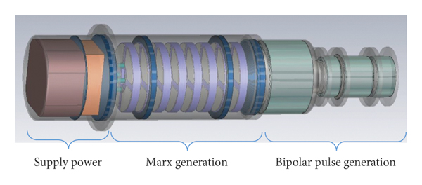
The charging power supply charges the Marx generator through a full bridge circuit, high-frequency transformer, and rectifiers. The maximum output peak voltage of the Marx generator is more than 1 MV. The high-voltage “wide” pulse input by the Marx generator is compressed into a monopole “narrow” pulse through a transmission line and a sharpening switch, and then, the bipolar pulse is generated by a ring cutoff switch and another sharpening switch.
The experimental results show that the test waveform of bipolar pulse is consistent with the simulation waveform of PSPICE software. The center frequency of the bipolar pulse is about 400 MHz, and the output peak power is more than 15 GW.
3. High-Voltage Pulse Generation
3.1. Structure of the Marx Generator
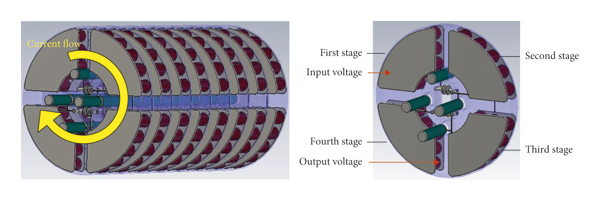
The high voltage to drive the bipolar pulse is generated by using a modified Marx generator. The capacitance of each stage is 6 nF, which is composed of twelve 50 kV/0.5 nF ceramic capacitors in parallel. The disk module is 40 mm thick with an interval of 35 mm between the two adjacent disk modules. Eight disk modules are stacked in series; the output of the former module is connected to the input of the latter module in two adjacent modules. The total length of the Marx core is 600 mm. When the Marx generator is operating, the discharge current spirals forward and passes through each sector capacitor bank in turn. The structure of the Marx generator is shown in Figure 2.
The structure diagram of the 32-stage Marx generator (as shown in the left figure), which consists of 8 disk modules, and each module contains four stages (as shown in the right figure).
3.2. Circuit Structure of the Marx Generator
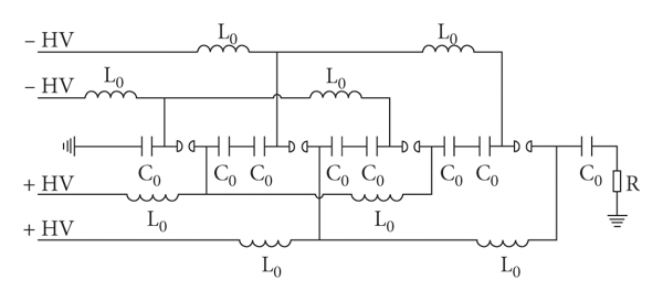
The circuit principle of the 8-stage Marx generator is shown in Figure 3, and all discharge switches are self-breakdown spark gap. Different from the Marx generator charged by positive and negative voltages [Reference Song, Li and Zhang19, Reference Song, Zhang and Li20], the modified Marx generator uses four charging channels, two of which are positive voltage and the other two are negative voltage. The advantage of this charging circuit topology is that the design of charging circuit structure is simplified and the cross of positive and negative charging inductors is avoided.
The circuit of the 8-stage Marx generator with a four-group charging loop.
3.3. Constant Current Charging Power Supply
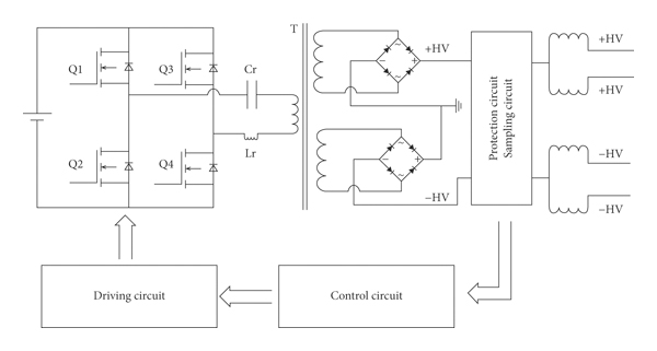
To make the system compact, the charging power supply was integrated to the end of the Marx generator. The charging power supply adopts the L-C constant current resonant charging mode. The control circuit outputs 2 PWM (Pulse Width Modulation) signals and drives the IGBT switch to turn the DC voltage into a 20-kHz periodic square voltage. Then, the periodic square wave voltage changes into ±35 kV high voltage after passing through the high-frequency transformer, rectifier circuit, protection circuit, etc. The circuit diagram is shown in Figure 4. Since a Marx generator module needs two positive voltage inputs and two negative voltage inputs, the isolated inductor is used to separate the positive voltage and negative voltage into two channels, as shown in the output section of Figure 4.
The circuit diagram of constant current charging power supply.
3.4. Spark Gap Switch
The discharge switch is a key component of the Marx generator, and its characteristics directly affect the working performance of the generator. The requirements of the discharge switch are short conduction time, good working stability, and small time-delay jitter. Since all switches of the generator are overvoltage self-breakdown, continuous clearance adjustment is considered in the switch design for the convenience of debugging. The spark gap switch adopts a planar cylindrical electrode, the electric field is evenly distributed, and the switch spacing is continuously adjusted by thread. The switch electrode with a diameter of 20 mm is made of stainless steel. To prevent the corona phenomenon, the electrode edge has a smooth transition of the fillet. The switches are placed in two rows in the center of the capacitor disk module, with no shielding between them. The ultraviolet light rays generated during switch discharge illuminate each other, accelerate the switch conduction, and facilitate the erect of the Marx generator. The structure and layout of the switches are shown in Figure 5.
Switch structure (a) and layout (b).
3.5. Design of the Isolation Inductor
When the Marx generator is charged, the current change rate dI/dt is very small. So, the isolation inductor is approximately a complete conductor, and the charging efficiency is approximately 100%. The isolation inductance does not affect the charging time and efficiency, while, when the Marx generator is discharged, the inductance of the isolation inductor affects the output peak voltage of the Marx generator.
Figure 6 shows the variation of output peak voltage of Marx with different isolation inductors (load resistance R = 500 Ω). As the inductance increases, the output peak voltage increases too, and the voltage waveform changes from an underdamped state to overdamped state. When the inductance reaches 10 μH, the output voltage differs a little from that of 100 μH. Considering the need of a compact design of the system, the isolation inductance is taken as 20 μH. The inductor adopts a hollow spiral structure, which is made by wrapping an enameled wire around an insulated cylinder. The length of the inductor is about 75 mm, which ensures no surface breakdown under the environment of high-voltage SF6 gas.
Influence of isolation inductance on the output voltage waveform of the Marx generator.
4. High-Power Bipolar Pulse Generation
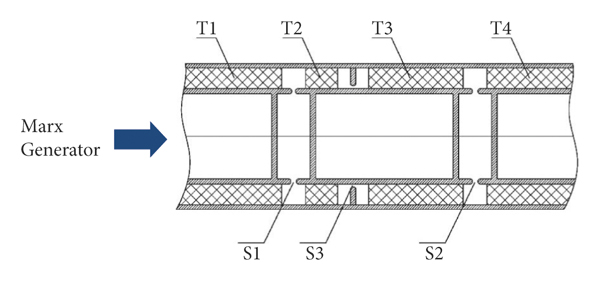
The high-power bipolar pulse generation circuit is shown in Figure 7. Because the output voltage front of the Marx generator is about tens of nanoseconds, it cannot be used to generate a bipolar pulse directly, so it needs to be compressed. When the switch S0 is on, the Marx generator charges the transmission line T1. When the charging voltage reaches or approaches the maximum voltage, the switch S1 is on, and the transmission line T1 charges T2 and T3. When the voltage pulse reaches the switch S2, the switch S2 does not conduct, resulting in total reflection. When the reflected voltage reaches the ground switch S3, the switch S2 and switch S3 conduct simultaneously (the switch S3 is short-circuit total reflection, and the voltage polarity is reversed), forming a bipolar pulse on the transmission line T4.
Circuit of high-power bipolar pulse generation.
According to the principle of bipolar pulse generation, Pspice software was used to simulate the generation of bipolar pulse. L marx is the sum of the equivalent inductance of Marx and the connection inductance between Marx and T1, and the total inductance is 5 μH. C marx is the equivalent capacitance of Marx, and the value is 0.1875 nF. The characteristic impedances of transmission lines T1, T2, T3, and T4 are all 10 Ω, and the electrical lengths are 1 ns, 0.3 ns, 0.8 ns, and 10 ns, respectively. R Load is the resistive load with a resistance of 10 Ω. The simulation results are shown in Figure 8. After the Marx generator charged with ±35 kV is discharged, a 920 kV voltage pulse was obtained on T1 after about 27 ns. At this moment, switch S1 is on, and transmission line T1 charges to T2 and T3. After 2.57 ns, switch S2 and S3 are on at the same time, and a bipolar pulse of about 400 kV is obtained on the T4, with an output power of about 16 GW and a central frequency of 400 MHz.
Simulated time-domain voltage waveform and bipolar pulse frequency-domain waveform.
The structure of the bipolar pulse generator is predicted in Figure 9. The device adopts a coaxial transmission line structure, and the sharpening switches S1 and S2 are ring switches, which are installed on the inner conductor of the transmission line. The gap of switches S1, S2, and S3 is 10 mm, 2.2 mm, and 2 mm, respectively. The switch cavities S1, S2, and S3 are filled with high-pressure nitrogen of 4 MPa, 7 MPa, and 7 MPa, respectively.
Structure diagram of the bipolar pulse generator.
When the ring switch breaks down, it can form multiple conductive channels, which can effectively reduce the inductance of the switch and accelerate the conduction speed. The ground switch S3 is also a ring structure, which is installed on the outer cylinder of the transmission line. Sharpening switch S1, S2, and ground switch S3 are made of stainless steel. Each switch has an independent switch cavity to facilitate air pressure adjustment. The switch cavity can withstand pressure greater than 10 MPa. The inner and outer conductors of the transmission lines T1, T2, T3, and T4 are also made of stainless steel. The outer conductor diameter is 200 mm, and the inner and outer conductors are filled with plexiglass as insulation support. The relative dielectric constant of plexiglass is 2.3.
5. Experimental Results
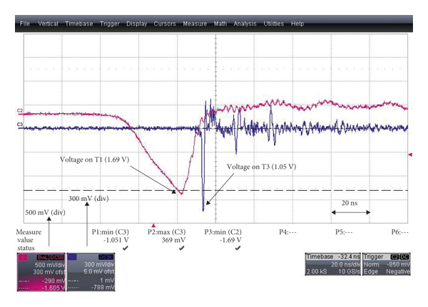
The pulse voltage signal in the process of bipolar pulse generation is detected by the capacitor voltage divider, and its bandwidth can reach 2 GHz. The capacitor voltage divider is set on the inner wall of the outer conductor of the transmission lines T1, T3, and T4, and their voltage ratio is 1271.4, 1095.8, 1155, respectively. The signal of the capacitor voltage divider is transmitted to the oscilloscope through a 50 dB attenuator and a 30 m coaxial cable whose attenuation coefficient is about 1.4 at the frequency of 400 MHz. The bandwidth of the oscilloscope (Lecroy waverunner 8254 M) is 2.5 GHz. The voltage waveforms obtained by the capacitor voltage divider on transmission lines T1 and T3 are shown in Figure 10. After the Marx generator charges the transmission line T1 for about 27 ns, the voltage on the transmission line T1 is about 950 kV (the measured value of the oscilloscope is 1.69 V). At this time, the switch S1 is on, and a monopole pulse with a pulse width of about 2 ns and amplitude of about 509 kV (the measured value of the oscilloscope is 1.05 V, which is the average value of 10 recorded data) is obtained on the transmission line T3.
Experimental voltage waveforms on transmission lines T1 and T3.
After the monopole pulse is reflected by switches S2 and S3, a high-power bipolar pulse is generated on the transmission line T4. The experimental bipolar pulse waveform and simulated waveform are shown in Figure 11. As can be seen from the figure, the generated bipolar pulse width is about 3.5 ns, the amplitude is 390 kV, and the output power is 15.2 GW. The experimental waveform is consistent with the simulated waveform.
Comparison of the experimental bipolar pulse waveform and the simulated waveform.
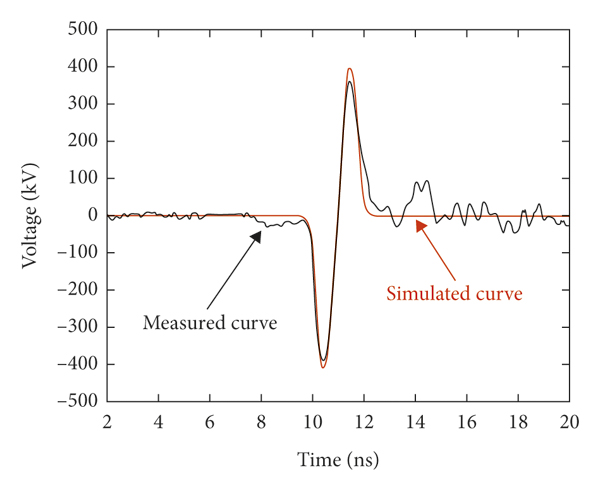
Since the electric length of transmission line T1 is 1 ns, its capacitance is about 100 pF. When the charging voltage on T1 is 950 kV, the input energy on T1 is 45.1 J. The power obtained on 10-ohm load is 15.2 GW, and the half width of the bipolar pulse waveform is about 1.75 ns, as shown in Figure 11. Through integral calculation, the output energy of the bipolar pulse generator is about 26.6 J, so the energy efficiency of the bipolar pulse generator is about 59%.
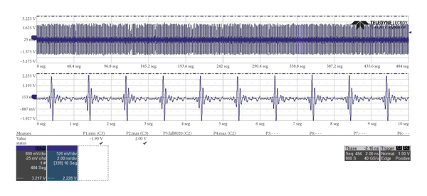
An experimental study on the repetition-rate characteristics of the bipolar pulse generator was carried out by replacing the resistive 10-ohm load with a high-power UWB antenna. The radiation system operated continuously for one minute at a repetition rate of 100 Hz and operated stably. Figure 12 shows the far-field radiation waveforms under the repetition rate operation condition. The cumulative number of operating pulses of the system has exceeded 105.
Far-field radiation waveforms of the bipolar pulse generator at 100 Hz repetition rate.
Due to the use of SF6 insulating gas, its poor thermal conductivity and ionization products are the main reasons for the performance degradation or failure of the bipolar pulse generation system. When SF6 gas is discharged and ionized, it will produce toxic or corrosive gases, such as SO2, H2S, and HF. These ionized gases will also seriously reduce the insulation performance of SF6 and affect the service life of the generator. After the experiment, the ionized SF6 gas needs to be discharged into a special collection container through a pipe.
6. Conclusions
In this paper, a high-power bipolar pulse generation system based on a modified Marx generator is designed; its size is φ400 mm × 1800 mm, and weight is about 200 kg. The modified structure Marx generator consists of 32 stages, including 8 disk-shaped modules, and each module contains four submodules. The structure combines ring and line structure. The disk-shaped modules are connected in a straight line, and each submodule is connected in a ring. Compared with the “linear” or “Z”-type Marx generator, the modified structure is greatly shortened in length. The total length of the Marx core is only 600 mm, with an output voltage pulse of more than 1 MV.
The bipolar pulse generator consists of four 10 Ω low-impedance coaxial transmission lines, two sharpening switches, and a cutoff switch. Compared with the bipolar pulse generated by Blumlein line, the bipolar pulse generated by the single line described in this paper is simpler in structure and easier in insulation design and debugging under higher power conditions, especially when the power exceeds 10 GW.
The simulation and experimental results show that a bipolar pulse with a width of about 3.5 ns, voltage of 390 kV, and output power of more than 15 GW was obtained on a 10-ohm transmission line. The experimental results are consistent with the simulation results. The bipolar pulse generator with a UWB antenna has been tested, and it can run steadily for one minute under the condition of 100 Hz repetition rate, and the cumulative lifetime is more than 105 pulses.
Data Availability
The data used to support the findings of this study are available upon request.
Conflicts of Interest
The authors declare no conflicts of interest.


 Open access