


NOMENCLATURE
- Δ
-
change
- BPR
-
bypass ratio
- ESFC
-
energy SFC (W/N)
- FCV
-
fuel calorific value (lower) (MJ/kg)
- Fn
-
net thrust (kN)
- HVLER
-
aircraft variant – hydrogen very large aircraft extended range
- HVLLR
-
aircraft variant – hydrogen very large aircraft long range
- HVLMR
-
aircraft variant – hydrogen very large aircraft medium range
- ISA
-
international standard atmosphere
- NOx
-
nitrogen oxides
- SFC
-
specific fuel consumption (kg/s/MN)
- SLS
-
sea level static
- TET
-
turbine entry temperature (K)
1.0 INTRODUCTION AND ANALYSIS METHOD
The use of hydrogen as a civil aviation fuel is an alternative to decarbonise aviation(1–Reference Verstraete3). Switching jet engine fuel to hydrogen promises to decarbonise civil aviation if hydrogen production is carbon free and aircraft engines deliver very low NOx emissions. Hydrogen also removes other harmful emissions such as unburnt hydrocarbons, aromatic compounds, sulphur oxides, soot and smoke. However, the use of hydrogen for civil aviation requires colossal changes in aircraft, infrastructure, management, safety and regulation. Such a change will be very expensive. However, the authors firmly believe that, socially and economically, it is a far superior alternative to the vast economic and social damage that will result from reducing air traffic. Hydrogen is a technological solution to provide combined sustainability in environmental, economic and social terms. With the appropriate (very large) investments, an introduction in approximately 15 years is conceivable.
Many tests and evaluations of hydrogen-fuelled aircraft have been carried out, from von Ohain’s hydrogen-fuelled demonstrator in the late 1930s(Reference Giffard4), the flight test of a B57-Canberra in the late 1950s(Reference Kaufman5) and the TU-155 in the late 1980s(6). More recently, significant tests at engine conditions to deliver hydrogen combustion with low NOx emissions are being carried out in the European project Enable H2(1).
For a swift change, several waves of innovation are needed. For early service (2035?), the first wave must maximise the use of existing design and technology. Later waves of innovation will deliver the full potential of hydrogen in the aircraft.
This study examines a possible scenario into the first innovation wave to offer aircraft decarbonisation scenarios long before 2050 by maximising the use of the current state of the art. This approach will enable a reduction of development costs and concentrate scarce research resources in the key hydrogen focused components. Such initial aircraft designs will not be optimal, but they may reduce development time and risk. It is hoped that this could bring entry into service forward by 15 years or more. The carbon savings achieved would be colossal. The authors ask: why not fully decarbonise civil aviation in 50 years? Figure 1 shows a scenario where five technology options are compared. The authors believe that the zero-carbon option in 50 years is feasible if decisive and wide-ranging international action is taken.
Comparison of five technology scenarios, all with the hypothesis of continuous growth in air traffic of 4% p/a. Baseline shows CO2 emissions with the continued use of current state-of-the-art equipment. The 25% and 50% results show the benefits of the immediate introduction of improved technology improvements that would yield, in 100 years, these respective improvements. The 50% gradual results show a gradual move to 50%, and H2+Electric shows a fully decarbonised scenario.

It is widely acknowledged that market forces alone will not bring about the changes needed. It would be necessary to adopt direct international financial support or economic–taxation measures to enable the transition to zero-carbon aviation. Techniques for evaluating the impact of different policy scenarios are available(Reference Nalianda7).
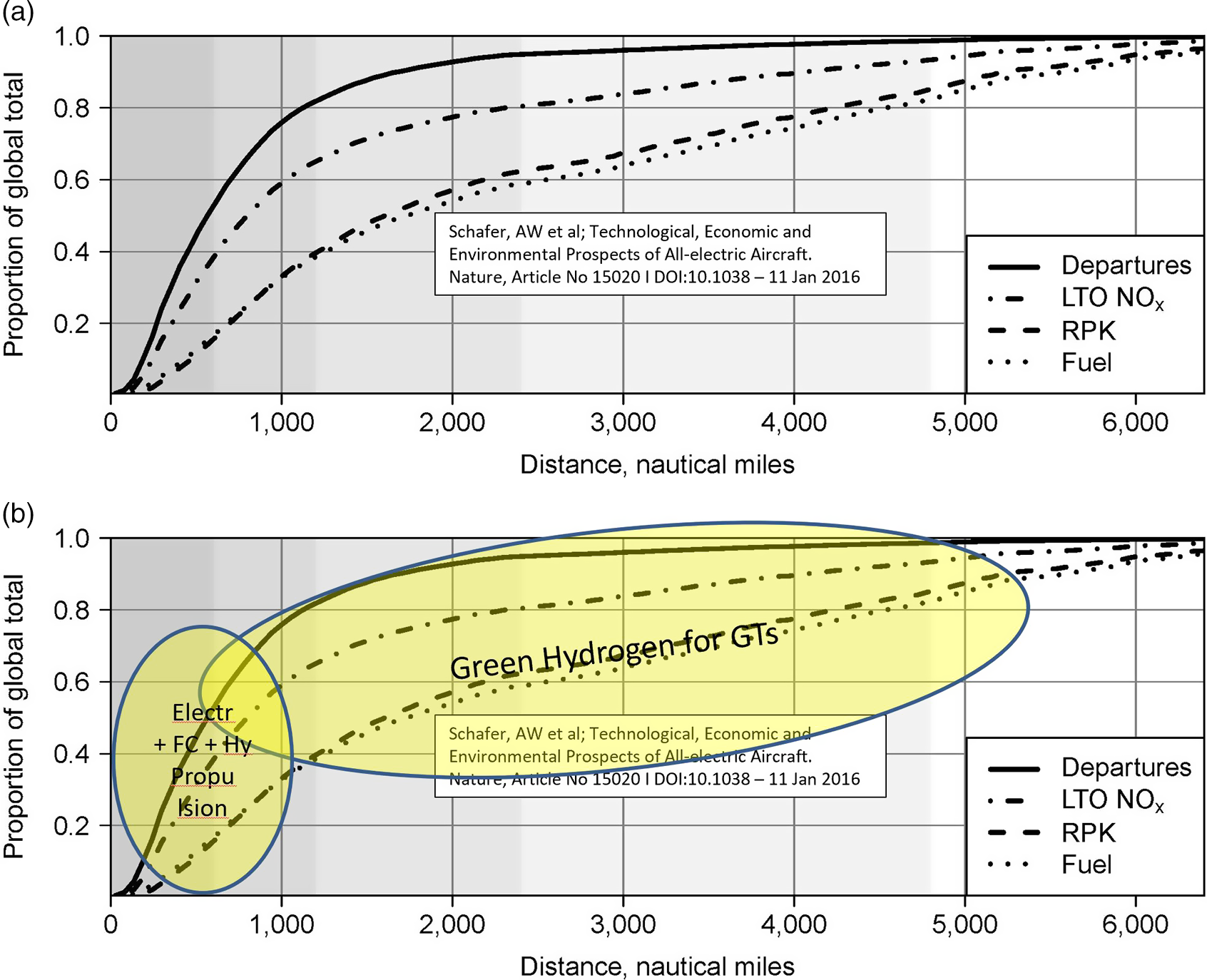
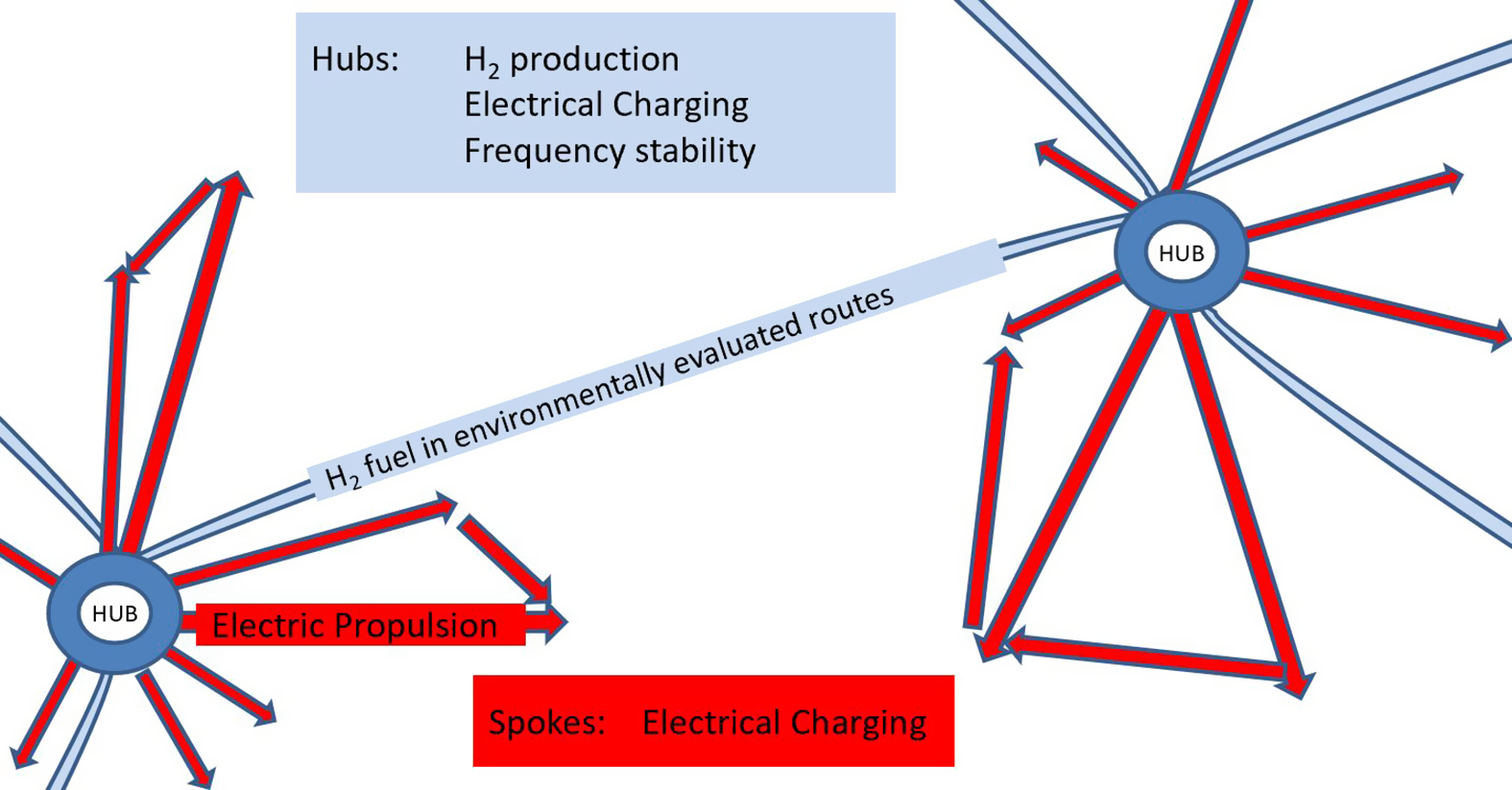
Fast decarbonisation is possible if successive waves of innovation are considered. In the first wave, for fast implementation, Fig. 2b shows how such a first wave of innovation could be shared between electric (including all electric, fuel cell electric and hybrid) and hydrogen propulsion systems. This may give rise to an increase in popularity of hub-and-spoke systems (Fig. 3) where inter-hub traffic is served by hydrogen-fuelled transports with gas turbine engines and the spokes by all-electric, fuel-cell electric and hybrid electric aircraft.
(a). Commercial aircraft traffic characteristics(Reference Schafer, Barrett, Doyme, Dray, Gnadt, Self, O’Sullivan, Synodinos and Torija8). (b) Commercial aircraft traffic characteristics(Reference Schafer, Barrett, Doyme, Dray, Gnadt, Self, O’Sullivan, Synodinos and Torija8) annotated by the authors on the basis of published electric propulsion capabilities and the H2 evaluation described here.
Schematic of hydrogen hub and electric propulsion spoke approach.
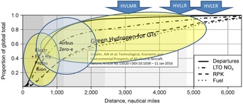
The maximum estimated range of the ‘Hydrogen for GTs’ bubble in Fig. 2b is shown at 5,500nm based on the results for the HVLER aircraft variant analysed here. In the longer term, third- and fourth-generation aircraft could be designed to exploit the synergies between electrical and hydrogen systems(Reference Nalianda and Singh9) to deliver improved engine and aircraft performance.
The study described here follows such an approach for a propulsion system in a medium/long-range aircraft design, where the focus is on the first wave of innovation aimed at a swift entry into service and the environmental reward is achieved by the faster deployment of carbon-free systems replacing carbon-emitting equipment. An attempt is made, via a hypothetical but reasonable approach, to answer a key question: What would a hydrogen-fuelled propulsion system look like if integrated into existing airliner design experience? A realistic option is proposed based on a derivative design inspired by existing technology for a wide-body transport.
Cycle characteristics of the turbofan engine

Through evaluation and analysis, the option of using an existing aircraft to achieve this objective was ruled out; it was apparent that such a vehicle would be very inefficient. A careful evaluation procedure was introduced (Huete et al. 2020-1) to down-select a reasonable vehicle from a wide range of options. It was concluded that the volume–mass relationships are such that a reasonable approach would be to consider a design that integrated the airframe of a 600tonne double-decker airliner (inspired by the Airbus A380(10)), with the wing and engines of a long-range twin-engine airliner (inspired by the Airbus A350-1000 with its Trent XWB turbofans(11)). The evaluation was an iterative process, and only the final result is shown here. This exercise gave rise to a family of three aircraft variants, labelled HVLMR, HVLLR and HVLER.
It is clear that integrating the necessary components would not be a straightforward matter, and the approach proposed here is a derivative design and not a retrofit. This could be accomplished within 15 years if sufficient research budgets are allocated very soon. It is also acknowledged that a significant challenge will arise from the systems needed to store, move and use hydrogen on board, the development of certification requirements, delivery of low NOx emissions systems and public support to decarbonise the sector. This public support is likely to be of a similar magnitude to the public investments and subsidies that underpinned the widespread use of renewable energy systems in the electricity generation industry.
2.0 ENGINE CHARACTERISTICS
The evaluation was an iterative process, concluding with the selection of a baseline jet engine that is inspired by a state-of-the-art high-bypass-ratio three-spool turbofan (Trent XWB(12)). Uisng TURBOMATCH (the Cranfield gas turbine performance simulation code(Reference Nikolaidis13)) the performance of turbofans using conventional and hydrogen fuels was evaluated. The TURBOMATCH analytical method uses gas turbine performance principles(Reference Palmer and Pilidis14) and is an iterative method based on component characteristics.
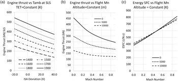
As expected, there are no major differences in engine performance arising from the use of hydrogen fuel, as shown in Table 1. SFC is expressed in a conventional way and also as ESFC, philosophically akin to the concept of heat rate, in wide use for land-based gas turbines. This is necessary because of the very large difference in the lower fuel calorific values, FCV, of conventional fuel and hydrogen (43.1 and 120MJ/kg, respectively)(Reference Cohen, Rogers and Saravanamuttoo15). The engine used in the three aircraft variants described below is always the same. The engine is designed for the aircraft variant with the highest thrust requirement; the lower thrust requirement of the other variants is met by adjusting the engine power setting.
The next step was an assessment of engine performance throughout the flight envelope using TURBOMATCH with hydrogen fuel in the calculations. The outputs are shown in Fig. 4, showing the thrust variation with ambient temperature (Fig. 4a) and with altitude and flight Mach number (Fig. 4b). Figure 4c shows the ESFC and its dependence on altitude and flight Mach number.
(a). Thrust versus SLS ISA temperature deviation. (b) Thrust versus flight Mach number. (c) ESFC versus flight Mach number.

3.0 FUEL TANK INTEGRATION
A major challenge with the use of hydrogen is the low density of the fuel, even in its liquid form. The fuel is to be stored at 21.5K and 1.25bar, so insulation will require a great deal of attention. The authors based the tank design philosophy on expanded analytical studies based on previous Cranfield work(Reference Goldberg16–Reference Goldberg, Nalianda, MacManus, Pilidis and Felder18). The tanks must be insulated to prevent heat leakage into the liquid hydrogen with no need for an active cooling system. Low-pressure storage does not demand thick walls. Fuel withdrawals through engine feeding lines reduce the tank pressure and temperature, while heat leakage increases them. Pressure and temperature is regulated through two mechanisms. To prevent excessive increases in pressure and temperature, due to heat leakage, a bleeding valve allows hydrogen to escape to a venting space in a safe way, restoring the pressure and temperature inside the tank. To avoid undesirably low pressure inside the tanks, warmer or preheated hydrogen can be fed back into the tanks from feeding or venting lines.
Several design schemes are possible, with either single or double metallic or composite walls. A wide range of insulation materials from foam to vacuum-jacketed multilayer insulation can be used. The resulting tanks deliver insulation properties ranging from nearly zero boil-off over extended periods of time, typically days, to short-range tanks, that can accomplish a 6h mission with boil-off rates below 0.15% per hour(Reference Goldberg16) (p. 3). Tank selection depends on not only the mission but also the infrastructure developed at airports for hydrogen aircraft. For airports without hydrogen infrastructure, requiring aircraft to arrive and park with large amounts of fuel, highly insulated tanks should be considered. For airports with a fully developed infrastructure, optimum tanks would require a much lighter insulation. The infrastructure plays a significant role in hydrogen development, not only because hydrogen needs to be produced onsite from renewable resources and would require safe storage and filling systems to be certified, but also due to the reutilisation system required for hydrogen left at the aircraft when stopped or parked overnight.
Due to the uncertainty regarding the pace at which such infrastructure will be developed, the tanks considered in this paper are aluminium double-walled foam-insulated tanks with boil-off rates below 0.15% per hour. The weight of the tanks considered here is 1.22 times the weight of the hydrogen contained. This results in a gravimetric efficiency (ratio of weight of hydrogen to weight of hydrogen plus tank) of around 0.45. Under optimum infrastructure development, the gravimetric efficiency could be increased to the 0.7+ range.
The authors, based on established aircraft and engine design and performance correlations(Reference Nikolaidis13,Reference Fielding19,Reference Raymer20,Reference Torenbeek21) , developed a method for the evaluation of aircraft and engine performance (Huete et al. 2020-1). Many iterations of different combinations were carried out. The final results of this analytical process are presented in Table 2, where the HVLMR, HVLLR and HVLER concepts are compared with the ‘design donor’ aircraft. These are used with the Cranfield propulsion system integration method Hermes/Orion(Reference Nalianda, Goldberg and Mastropierro22) to confirm the combined aircraft and engine performance. Hermes/Orion uses TURBOMATCH for engine performance calculations.
Comparison HVLMR, HVLLR and HVLER with the ‘design donor’ aircraft
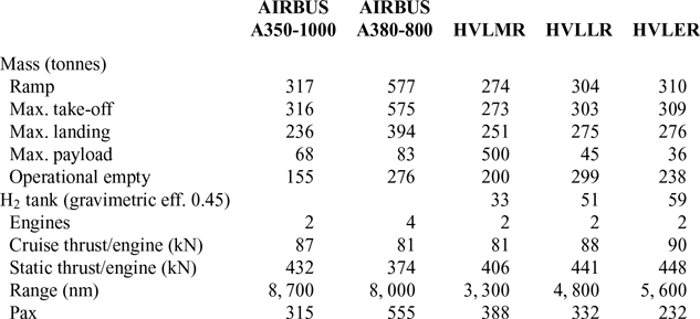
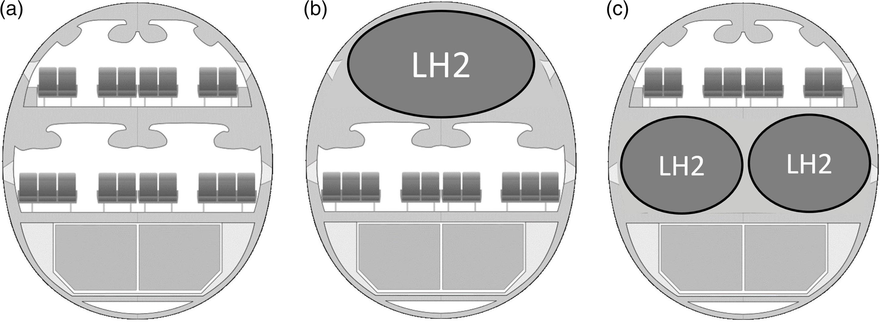
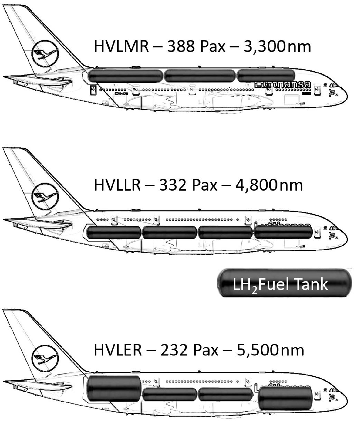
Figure 5a shows the airframe of the aircraft used for the study. The aircraft has two decks to carry passengers, the lower deck being larger than the upper one. The authors examined three variants of a hydrogen-fuelled airliner derived from this concept: HVLMR, HVLLR and HVLER; for hydrogen medium, hydrogen long and hydrogen extended range. The concepts of long and extended ranges apply to hydrogen in this case and imply much shorter flights than the capabilities of a modern conventional airliner. The first variant, HVLMR, considers the use of the upper deck to house fuel tanks, while the HVLLR is conceived with the fuel tank in the lower deck and HVLER with a combination.
(a) Baseline image (b) HVLMR layout (c) HVLLR layout (Image from Ssolbergj, Steff and Clem Tillier - Creative Commons licensed modified by the authors).
HVLMR, HVLLR and HVLER concepts. Images courtesy of Lufthansa(10) and modified by the authors.
Distances between selected airports, a measure of the usefulness of HVLMR, HVLLR and HVLER (Wikipedia)

HVLMR, HVLLR and HVLER capabilities(Reference Schafer, Barrett, Doyme, Dray, Gnadt, Self, O’Sullivan, Synodinos and Torija8) annotated by the authors and including the authors understanding of the Airbus Zero-e concepts(23).

4.0 INTEGRATED CAPABILITY
To offer a visual illustration of the aircraft concepts, the authors modified existing aircraft artwork(10) and produced authors impressions of the HVLMR, HVLLR and HVLER. These are shown in Fig. 6 with estimates of range and passenger capacity. Table 3 lists a compilation of distances between major cities obtained from Wikipedia to give a measure of the usefulness of the HVLMR, HVLLR and HVLER aircraft.
The estimated vehicle capability, for an introduction-accelerator philosophy, is good. It does not match the payload or very long ranges of current aircraft using conventional fuels, but it fares very well as an introductory accelerator technology to decarbonise aviation. Furthermore, Fig. 7 shows that the range offered covers more than 98% of existing aircraft departures and accounts for 90% of total fuel consumption. So, the remaining small fraction of very long-range flights could be serviced with one additional stop. It is expected that, in this scenario, the impact on fuel consumption will actually be beneficial because it is well known that significantly less fuel is required if a conventional aircraft flies two 8,000km legs instead of a 16,000km flight nonstop, although in the case of hydrogen the benefit will be significantly smaller because of the much higher energy density of the fuel, requiring a smaller fuel fraction of the total aircraft weight.
During this early investigation, it became apparent that the tank gravimetric efficiency is a parameter that will very significantly influence the performance characteristics of the integrated aircraft and powerplant. A detailed evaluation is being pursued independently (Huete et al. 2020-2)
5.0 CONCLUSIONS AND RECOMMENDATIONS
This paper describes an investigation into three hypothetical propulsion integration configurations with different tank locations for storing fuel. The investigation is philosophical in nature and is backed by detailed calculations. A family of civil aircraft using hydrogen fuel in gas turbine engines could be developed using the main components of two existing aircraft as a basis for the design. A very large two-deck transport design would provide the fuselage, while the wings, engines and tail surfaces would be derived from a very long-range twin. The family would comprise three configurations: HVLMR, HVLLR and HVLER. This family exhibits a payload and range that is significantly smaller than the ‘donor’ aircraft, but its characteristics are sufficiently attractive to be considered as a launch option for a first generation of zero-carbon aircraft. The range of the HVLER is chosen strategically to allow flights from any point on the planet to any other with just one stop. Figure 7 shows the strategic positioning of the family.
There may be many candidate aircraft to enter early service, but HVLMR, HVLLR and HVLER appear to offer sufficient promise to be considered as first-generation candidates for larger vehicles with longer ranges. As technologies mature, the performance of the aircraft of later generations would be better. In this context, a parameter of crucial importance, the tank gravimetric efficiency, is currently being evaluated by authors examining the proposed concepts(Reference Verstraete3) and original analysis. Another aspect under investigation is the ability to burn hydrogen in the combustor with very low NOx emissions(1). The approach in this investigation is to use combustors with very small orifices to mix air with fuel, procure good mixing characteristics delivering a lower primary zone fuel-to-air ratio and lower flame temperature, capitalising on the much wider flammability limits of hydrogen. This approach appears to be a good candidate solution at the expense of a small, acceptable weight and length penalty to the engine. Beyond carbon and NOx emissions, contrails also deserve detailed consideration. It is anticipated that, initially, contrail mitigation will be via rerouting flights(Reference Nalianda7). This approach is very promising to completely avoid persistent contrails at the expense of a few (1–3) additional percent in fuel burn. The integration of the fuel system and the components required is likely to follow known approaches(Reference Brewer, Morris, Davis, Versaw, Cunnington, Riple, Baerst and Garmong24) updated. Given the reduced luminosity of hydrogen flames, it is anticipated that heat transfer will be less aggressive than what is experienced with conventional fuels, so conventional combustor cooling arrangements are probably adequate. The same is argued here for turbine cooling requirements. Nonetheless, these matters deserve detailed examination.
Current detailed work is showing(1) that health and safety at airports and on aircraft can be managed by careful attention to detail and appropriate investments. There will be many certification hurdles, in particular arising from the need for extensive changes to certification rules. The development process could comprise two parallel streams. The first would focus on the development of the aircraft and engines using conventional fuel to test the handling quality of the vehicles. In parallel, an existing four-engine transport could be modified to use hydrogen fuel in two of the four engines to test all the systems associated with hydrogen in a twinjet; the remaining two engines would operate on conventional fuel while the hydrogen systems are developed to achieve high reliability and functionality. These parallel streams would probably last about a decade and serve as a platform for the dialogue with certification authorities to adapt rules to hydrogen fuel, supporting a zero-carbon reality.
Of course, there are also the questions of airport infrastructure and the production of zero-carbon hydrogen on a vast scale. This may be from seawater electrolysis to prevent unhelpful competition with scarce freshwater resources. Undoubtedly, all of these developments will cost hundreds of billions of pounds (or euros or US dollars), but the authors firmly believe that these costs are acceptable to migrate to zero carbon an industry that brings so many technical, social and economic benefits.
ACKNOWLEDGEMENTS
The authors acknowledge the support of Lufthansa via the provision of artwork used in this paper and for their interest in this environment-enhancing project.


 Open access