


Introduction
Minerals that belong to the polybasite group are among the most widespread Ag-sulfosalts in nature. The broad nomenclature of this group was due to their wide As–Sb, Ag–Cu isomorphism and the existence of more polytypes (monoclinic, trigonal) was ambiguous for a long time. Eventually the published nomenclature rules of Bindi et al. (Reference Bindi, Evain, Spry and Menchetti2007c) clarified that the members of polybasite group exhibit the general formula [M 6T 2S7][Ag9CuS4] with M = Ag,Cu and T = As,Sb and their crystal structure can be described as formed by two pseudo-layer modules: module layer A [M 6T 2S7]2– and module layer B [Ag9CuS4]2+. Members with As>Sb are pearceites and those with Sb>As are polybasites. Subsequent to Bindi et al. (Reference Bindi, Evain, Spry and Menchetti2007c) members with a Cu-dominant occupation at the M position of an A module layer (i.e. with total Cu contents > 4.00 atoms per formula unit, apfu) were defined as the minerals cupropearceite and cupropolybasite (Bindi et al., Reference Bindi, Evain, Spry, Tait and Menchetti2007d) and a Se-rich member with the formula [(Ag,Cu)6(Sb,As)2(S,Se)7][Ag9Cu(S,Se)2Se2] was defined as the mineral selenopolybasite (Bindi et al., Reference Bindi, Evain and Menchetti2007b). More recently, benleonardite [Ag6(Sb,As)2S6Te] [Ag9Cu(S,Te)2Te2] has also been recognised as a member of this group (Bindi et al., Reference Bindi, Stanley and Spry2015a).
In the approved members of this group, contents of ∼1 apfu Cu in the B module layer [Ag9CuS4] have been typically reported (Bindi et al., Reference Bindi, Evain and Menchetti2006, Reference Bindi, Evain and Menchetti2007a, Reference Bindi, Evain and Menchetti2007b, Reference Bindi, Evain, Spry and Menchetti2007c, Reference Bindi, Evain, Spry, Tait and Menchetti2007d), with only two exceptions. Bindi and Menchetti (Reference Bindi and Menchetti2009) described polybasite-M2a2b2c with only 0.43 apfu Cu determined by electron probe microanalysis and 0.50 apfu according to single-crystal data. The second is the case of benleonardite, for which, based on single-crystal data, Bindi et al. (Reference Bindi, Stanley and Spry2015a) found the formula [Ag6(Sb,As)2S6Te] [Ag9Cu(S,Te)2Te2] but earlier published chemical data show only minimal Cu contents (for Bambolla, Ivigtut, Um Samiuki occurrences up to 0.31 wt.%; for Gies and Mayflower contents up to 2.38 wt.% Cu). The first Cu-free member, argentopearceite, identified at the deposit Mikulov (Czech Republic), was approved by the Commission on New Minerals, Nomenclature and Classification of the International Mineralogical Association (IMA 2020-049; Sejkora et al., Reference Sejkora, Plášil, Makovicky, Škácha, Dolníček and Gramblička2020). Later, its Sb-analogue, the mineral argentopolybasite was described by Števko et al. (Reference Števko, Mikuš, Sejkora, Plášil, Makovicky, Vlasáč and Kasatkin2023) and Bindi et al. (Reference Bindi, Keutsch, Topa, Kolitsch, Morana and Tait2023).
As the mineral studied from the Mikulov and Moldava deposits has As>Sb and the structural position ‘Cu’ of the B module layer (Bindi et al., Reference Bindi, Evain, Spry and Menchetti2007c) is dominated by Ag, it has been named argentopearceite to indicate the Ag-dominant analogue of pearceite. Moreover, as it exhibits the 221 unit-cell type, the full name for the polytype is argentopearceite-T2ac, the Ag-dominant analogue of pearceite-T2ac (Bindi et al., Reference Bindi, Evain, Spry and Menchetti2007c). The holotype specimen of argentopearceite-T2ac from Mikulov is deposited in the collections of the Department of Mineralogy and Petrology, National Museum in Prague, Cirkusová 1740, 193 00 Praha 9, Czech Republic under the catalogue number P1P 35/2020. The studied material (cotypes) from the Moldava deposit are deposited in the same collection under the catalogue numbers P1N 64.380, P1N 66.881 and P1N 90.431.
Occurrence
A hand-sized sample of argentopearceite-T2ac was recovered in 2010 from the mine dump of the abandoned Lehnschafter mine. This is the largest, and probably the most important, mine in the Mikulov–Hrob base-metal ore district and is located 9 km NW of Teplice in the Krušné hory (Erzgebirge), Czech Republic. The GPS coordinates of the occurrence of argentopearceite-T2ac are 50°41’26.960”N, 13°43’16.547”E. The first remark about mining in this area comes from the middle of the 15th century, but the greatest mining boom lasted from the beginning of the 16th century until the 30-year war. All later mining efforts were not as successful and mining in this area finished at the end of the 19th century. Total silver production here is estimated at 16,000 kg (Dvořák et al., Reference Dvořák, Gramblička, Radoň and Števko2012). Kratochvíl (Reference Kratochvíl1957–1966) compiled the list of local minerals and Sattran (Reference Sattran1959) published the first study of this base-metal ore district and its mineral assemblage. The ore district is represented by the quartz-dominated As–Ag–Pb veins, located in gneisses of the crystalline mantle of Fláje granite massif, and which predominantly fill the oldest postmetamorphic faults running in a NNE direction (0–30°). Hydrothermal veins are of young-Variscan age (Sattran, Reference Sattran1959). The majority of the veins contain only the oldest high-temperature stage of grey quartz with disseminated pyrite and arsenopyrite, the younger second stage of druse quartz with common sulfides (arsenopyrite, galena, sphalerite, pyrite, tetrahedrite and chalcopyrite) is less abundant, and a third stage with Ag-sulfides and sulfosalts (acanthite, pyrargyrite, proustite, miargyrite, and hereby described argentopearceite) in white quartz with dolomite and calcite occurs only sporadically in thicker veins. The total absence of copper minerals is characteristic of this third stage of mineralisation. Argentopearceite is associated with proustite in quartz gangue.
Subsequently, argentopearceite was also determined in the museum samples labelled ‘pearceite’ (National Museum Prague collection, samples P1N 64.380, P1N 66.881 and P1N 90.431) from the abandoned fluorite deposit of Moldava (mined 1960–1994 with a production of ∼690 thousand tons of fluorite ore), located 16 km northwest of Teplice in the Krušné hory, Czech Republic (GPS: 50°43’19.1”N, 13°38’58.9”E). The Moldava deposit is represented by two main fluorite-quartz-baryte veins (named Josef and Papoušek) with NW–SE direction, which can be traced for ∼5 km. They were verified up to a depth of 600 m below the surface by boreholes. The thickness of veins is usually 2–3 m, locally increasing to 6 m. The vein-filling is massive or contains cavities with green, yellow and violet fluorite crystals (Fengl, Reference Fengl1998). The strongly supergene-altered Ag-rich mineralisation (acanthite, proustite, silver, argentopearceite, galena, tennantite etc.) in the Josef vein was discovered in 1968 at the fifth level of the Josef shaft (150 m below the surface) and continued up to the 7th level at the depth of 300 m (Fengl et al., Reference Fengl, Jansa, Novák and Reichmann1981). Its rich mineralogy (more than 100 known mineral species) was studied by Fengl et al. (Reference Fengl, Jansa, Novák and Reichmann1981) and more recently by Sejkora and Řídkošil (Reference Sejkora and Řídkošil1994), Sejkora et al. (Reference Sejkora, Řídkošil and Šrein1994, Reference Sejkora, Čejka, Šrein, Novotná and Ederová1998, Reference Sejkora, Čejka and Šrein2001), Sejkora and Škácha (Reference Sejkora and Škácha2015), and Sejkora (Reference Sejkora2024). Argentopearceite is associated there with acanthite and proustite in fluorite gangue.
Physical and optical properties
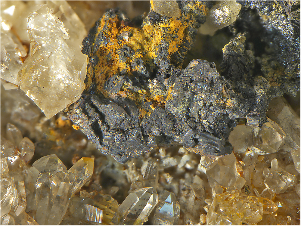
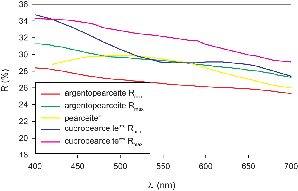
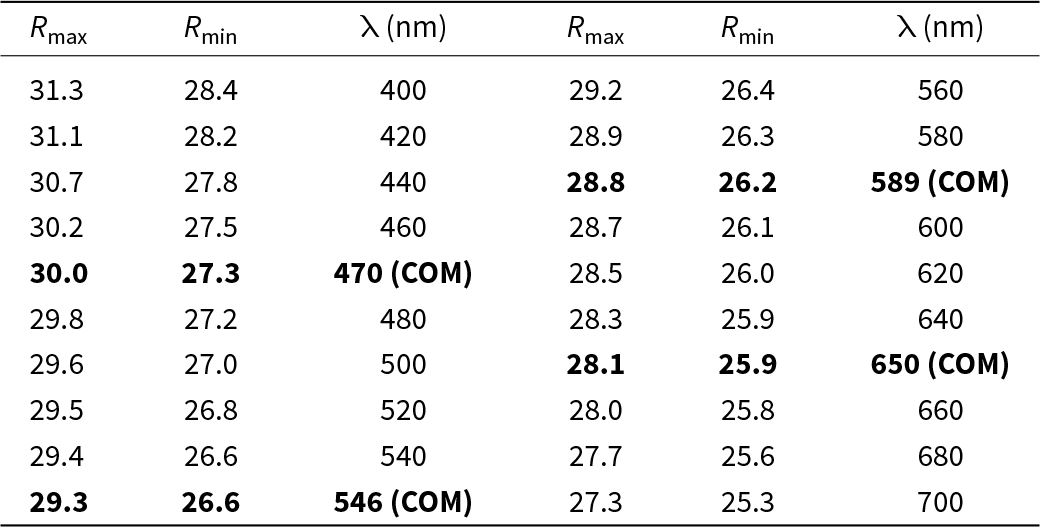
Argentopearceite from Mikulov forms irregular aggregates up to 2–4 mm across in cavities of quartz gangue, partly composed of tabular (pseudo)hexagonal crystals up to 0.8 mm in size (Fig. 1). The mineral is dark grey to black (tarnished to brown tints) and is opaque in transmitted light; it has a metallic lustre and greyish black streak. No cleavage was observed; the fracture is conchoidal. The calculated density (Z = 4) for the unit-cell parameters refined for the single-crystal X-ray diffraction data is 6.29 g/cm3; both for the empirical and ideal formula. Mohs hardness is assumed to be ∼3 by scratch tests. In reflected light, argentopearceite is grey with a greenish shade. Bireflectance was not observed. Pleochroism is very weak. Anisotropy under crossed polars is moderate with weak greenish and green–blue tints. Internal reflections were not observed. Reflectance spectra were measured in air with a TIDAS MSP400 spectrophotometer attached to a Leica microscope (20× objective) using a WTiC (Zeiss no. 370) standard. The results from the 400–700 nm range are given in Table 1 and plotted in Fig. 2, along with published data for pearceite and cupropearceite (Criddle and Stanley, Reference Criddle and Stanley1993; Picot and Johan, Reference Picot and Johan1982).
Aggregate of argentopearceite-T2ac, partly composed of (pseudo)hexagonal tabular crystals in the cavity of quartz gangue; Mikulov (holotype P1P 35/2020); FOV 5 mm.

Reflectivity curves for argentopearceite-T2ac from Mikulov compared with published data for pearceite* (Picot and Johan, Reference Picot and Johan1982) and cupropearceite** (Criddle and Stanley, Reference Criddle and Stanley1993); note Criddle and Stanley (Reference Criddle and Stanley1993) named their mineral pearceite, but the determined Cu content (18.8 wt.%; 5.92 apfu Cu) indicates it as cupropearceite defined by Bindi et al. (Reference Bindi, Evain, Spry, Tait and Menchetti2007d).

Reflectance values (%) for argentopearceite from Mikulov*

* The reference wavelengths required by the Commission on Ore Mineralogy (COM) are given in bold.
At the Moldava deposit, argentopearceite occurs as groups of steel to dark grey hexagonal tabular crystals up to 1–3 mm in size in druse cavities of fluorite gangue or fine-grained veins and aggregates up to 1 cm in size in association with acanthite and proustite.
Chemical composition
Chemical analyses of argentopearceite from both occurrences were obtained using a Cameca SX100 electron microprobe (National Museum, Prague) operating in wavelength-dispersive mode (25 kV, 2–5 nA and 10–15 μm wide beam). The following standards and X-ray lines were used to minimise line overlaps: Ag (AgLα), Au (AuMα), Bi (BiMβ), CdTe (CdLα), Co (CoKα), chalcopyrite (CuKα, SKα), FeS2 (FeKα), HgTe (HgMα), NaCl (ClKα), Ni (NiKα), NiAs (AsLβ), PbS (PbMα), PbSe (SeLβ), PbTe (TeLα), Sb2S3 (SbLα), Tl(Br,I) (TlLα) and ZnS (ZnKα). Concentrations of elements other than those reported in Tables 2 and Supplementary Table S1 were below detection limits (ca 0.03–0.05 wt. %). Raw intensities were converted to the concentrations of elements using the automatic ‘PAP’ (Pouchou and Pichoir, Reference Pouchou, Pichoir and Armstrong1985) matrix-correction procedure.
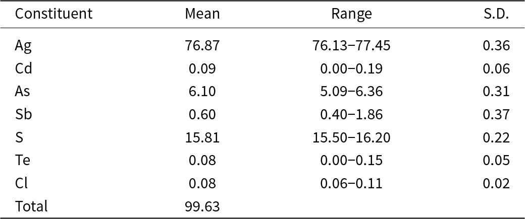
Chemical data (wt.%) for argentopearceite from Mikulov (crystal used for single crystal study), average of 15 analyses

S.D. = estimated standard deviation.
Analytical data for the argentopearceite crystal used for the single-crystal study (n = 15) are given in Table 2; it leads to the empirical formula calculated on the basis of 29 apfu (Ag15.95Cd0.02)Σ15.97(As1.82Sb0.11)Σ1.93(S11.03Cl0.05Te0.01)Σ11.09. The simplified formula is Ag16(As,Sb)2S11 (summary) or [Ag9AgS4][Ag6(As,Sb)2S7] (structural form of the polybasite group). The ideal formula is Ag16As2S11, which requires Ag 77.45, As 6.72 and S 15.83 a total of 100.00 wt.%. Later, additional grains from the holotype sample from Mikulov were analysed with similar results (Supplementary Table S1), the observed Cu contents do not exceed 0.08 apfu and the average empirical formula is (Ag16.18Cu0.04)Σ16.22(As1.84Sb0.05)Σ1.89(S10.84Cl0.04Te0.02)Σ10.90.
The chemical composition of three samples from the Moldava deposit also agrees very well with the ideal argentopearceite formula; analytical data are given in Supplementary Table S1. The observed Cu contents reach at most 0.16 apfu and their average empirical formulas (with catalogue numbers) are the following: (Ag16.07Cu0.02)Σ16.09As1.92(S10.93Cl0.05Te0.02)Σ11.00 (P1N 90.431), (Ag16.17Cu0.09)Σ16.26As1.89(S10.80Cl0.04Te0.01)Σ10.85 (P1N 66.881) and (Ag16.16Cu0.07)Σ16.23As1.92(S10.79Cl0.05Te0.02)Σ10.86 (P1N 64.380).
X-ray crystallography and structure determination
Powder diffraction
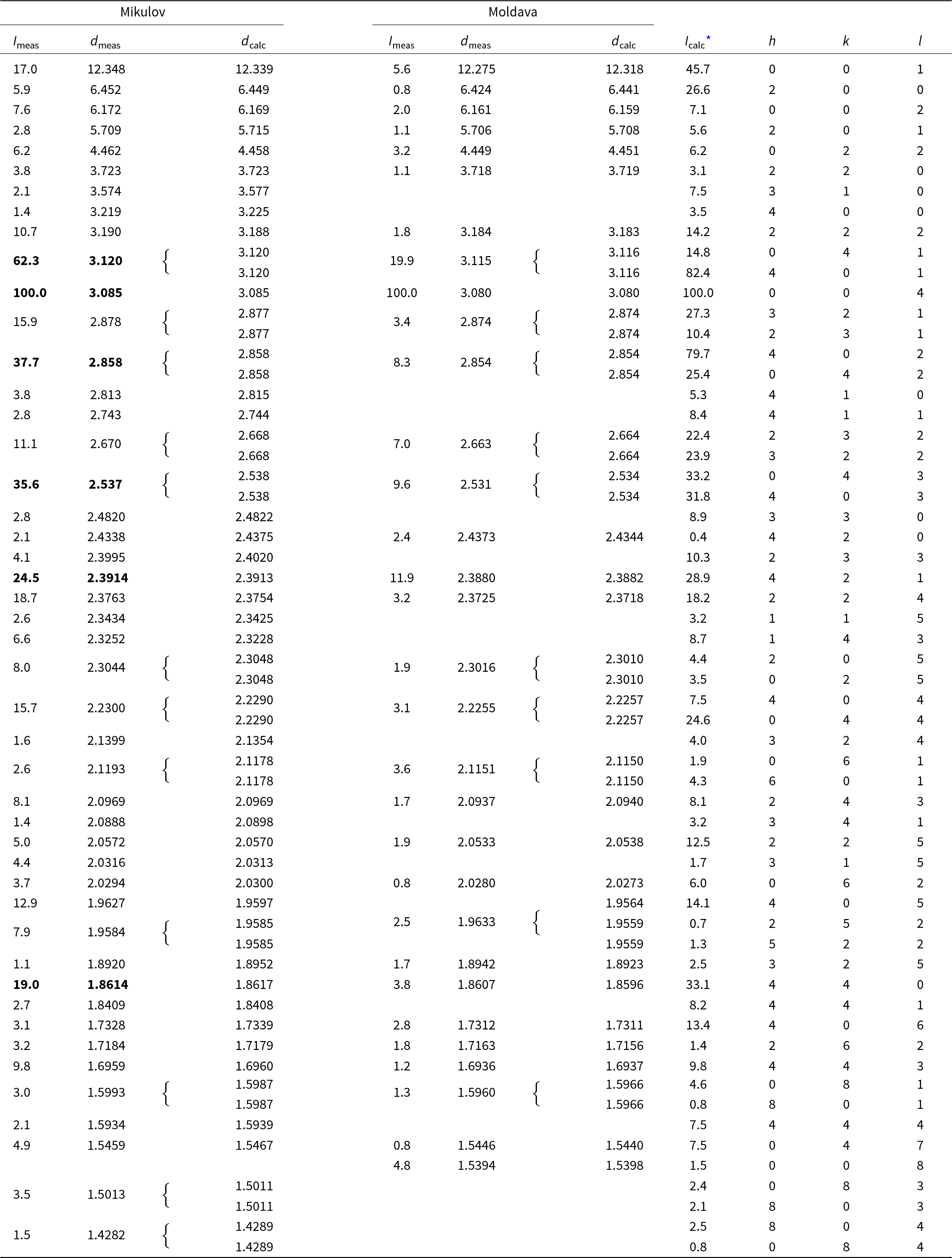
Powder X-ray diffraction data of argentopearceite were recorded at room temperature using a Bruker D8 Advance diffractometer equipped with a solid-state LynxEye detector and secondary monochromator producing CuKα radiation housed at the Department of Mineralogy and Petrology, National Museum, Prague. The instrument was operated at 40 kV and 40 mA. To minimise the background, the powdered samples were placed on the surface of a flat silicon wafer. The powder pattern was collected in the Bragg–Brentano geometry in the range 3–70°2θ, step size 0.01° and counting time of 20 s per step (total duration of the experiment was c. 30 hours). The positions and intensities of diffractions were found and refined using the Pearson VII profile-shape function of the ZDS program package (Ondruš, Reference Ondruš1993); data are given in Table 3. The differences between intensities observed for the samples from Mikulov and Moldava samples and those calculated on the basis of the refined structural model are related to the preferred orientation and other textural effects. Unit-cell parameters were refined by the least-squares program of Burnham (Reference Burnham1962) for trigonal space group P321 (#150) as follows – Mikulov: a = 14.8934(18), c = 12.339(2) Å, V = 2370.3(6) Å3 and Z = 4; Moldava: a = 14.8741(16), c = 12.318(2) Å and V = 2360.1(5) Å3. The c:a ratio calculated from unit-cell parameters is 0.8285 (Mikulov) and 0.8282 (Moldava).
Powder X-ray diffraction data (d in Å) for argentopearceite from Mikulov and Moldava; the six strongest diffractions are reported in bold

I calc* - relative intensity calculated using the software PowderCell2.3 (Kraus and Nolze, Reference Kraus and Nolze1996) on the basis of the structural model given in Tables 4 and 5.
Single-crystal X-ray diffraction (SCXRD)
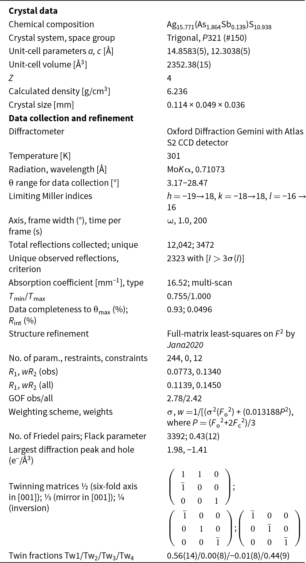
Single-crystal diffraction data of argentopearceite were collected from the holotype specimen from Mikulov at room temperature on an Oxford Diffraction Gemini diffractometer equipped with a standard sealed X-ray tube (graphite monochromatised MoKα radiation, λ = 0.71073 Å) and an Atlas S2 CCD detector. The raw data reduction was done using CrysAlisPro Version 1.171.39.46 software (Rigaku, 2019). The data were corrected for Lorentz factor, polarisation effect and absorption (multi-scan, ABSPACK scaling algorithm; Rigaku, 2019). The crystal structure of argentopearceite was solved from the diffraction data using the SHELXT program (Sheldrick, Reference Sheldrick2015) and refined using the Jana2020 software (Petříček et al., Reference Petříček, Palatinus, Plášil and Dušek2023). The crystal was modelled as a four-fold twin due to metric merohedry twinning (trigonal<hexagonal; diffraction type II; Petříček et al., Reference Petříček, Dušek and Plášil2016). We employed the third-order anharmonic Gram–Charlier development (see, e.g. Volkov et al., Reference Volkov, Charkin, Firsova, Aksenov and Bubnova2023) to describe the Debye-Waller factors for some of the Ag atoms that behave strongly anharmonically in the structure studied. The refined values were checked for significance (shift vs. error). The use of the Gram–Charlier development and corresponding data handling and refinement were discussed recently by Plášil et al. (Reference Plášil, Sejkora, Dolníček, Petříček, Désor, Majzlan, Gross, Möhn and Schürmann2024). The Wilson’s correction was applied during the refinement, preventing the statistical bias in the least-squares refinement (Wilson, Reference Wilson1976). Details of data collection and refinement are given in Table 4. Fractional atomic coordinates and equivalent isotropic displacement parameters are reported in Table 5 and Table 6 reports selected bond distances. Further details of the data collection, crystallographic parameters, and the fit statistics are given within the crystallographic information files provided as Supplementary material. The Vesta program (Momma and Izumi, Reference Momma and Izumi2011) was used to plot the electron density and the isosurface for atomic displacement parameters (ADPs) of the Ag atoms, all other structrure drawings were done using the Diamond4 program (Crystal Impact). For charge distribution analysis and other polyhedral-concerning calculations (Table 7), the program ECoN21 (Ilinca, Reference Ilinca2022) was used.
Summary of data collection and refinement for argentopearceite-T2ac from Mikulov

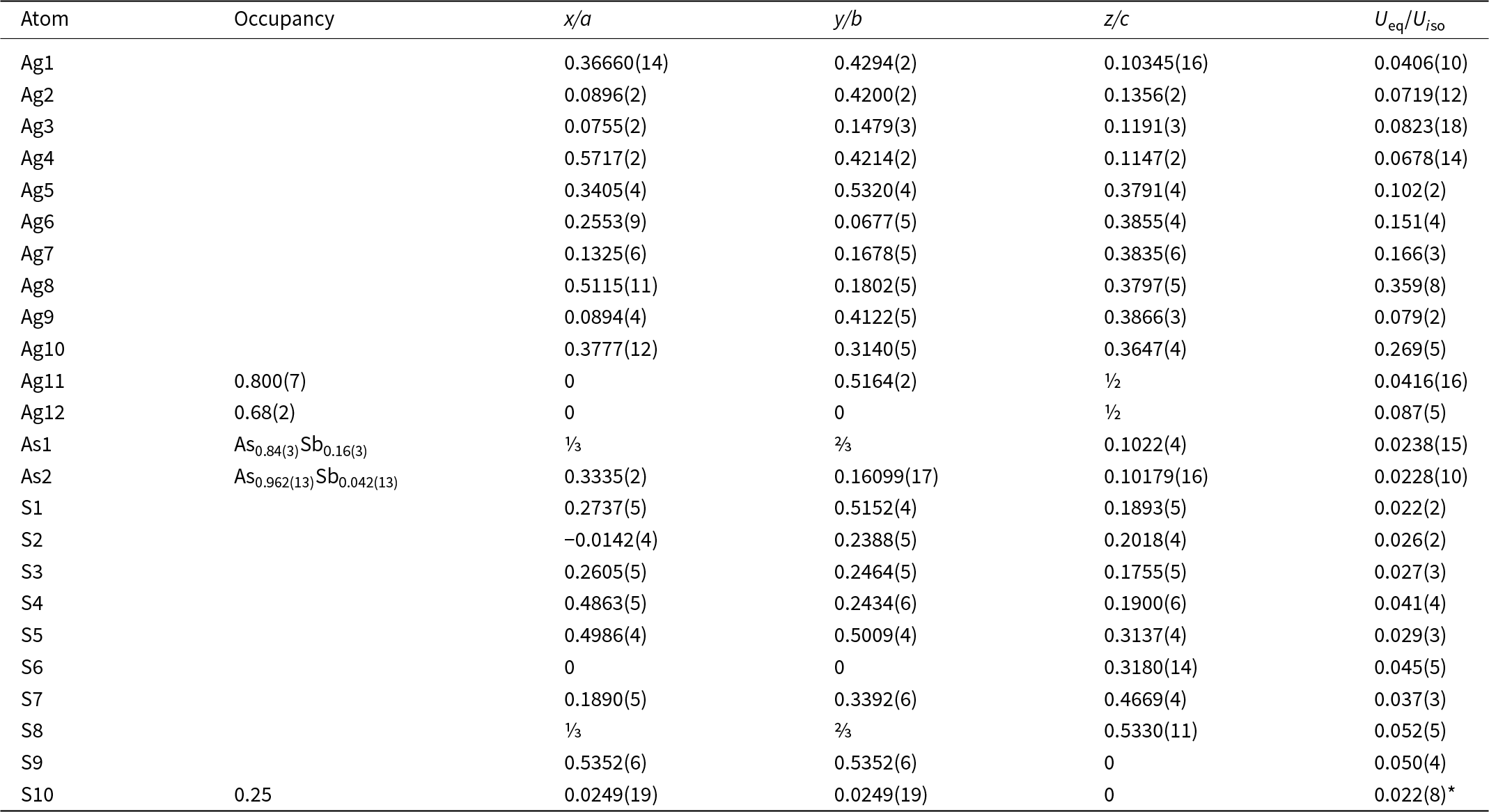
Atom positions, occupancy factors and displacement parameters (in Å2; equivalent or isotropic – marked with *) for the structure of argentopearceite-T2ac from Mikulov

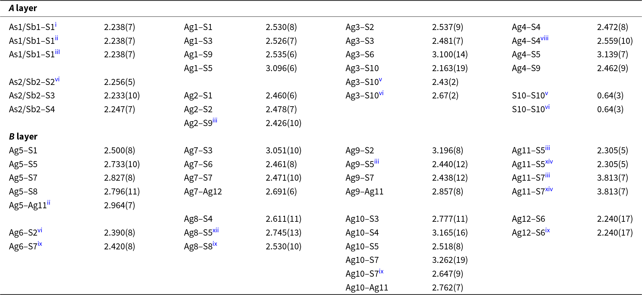
Selected interatomic distances (in Å) and polyhedral measures for argentopearceite-T2ac structure from Mikulov

Symmetry codes: (i) y, x, –z; (ii) –y+1, x–y+1, z; (iii) –x+y, –x+1, z; (iv) x–y, –y+1, –z; (v) –y, x–y, z; (vi) –x+y, –x, z; (vii) –x, –x+y, –z; (viii) –x+y+1, –x+1, z; (ix) y, x, –z+1; (x) –x+1, –x+y+1, –z+1; (xi) x–y, –y, –z+1; (xii) –y+1, x–y, z; (xiii) –x, –x+y, –z+1; (xiv) x–y, –y+1, –z+1.
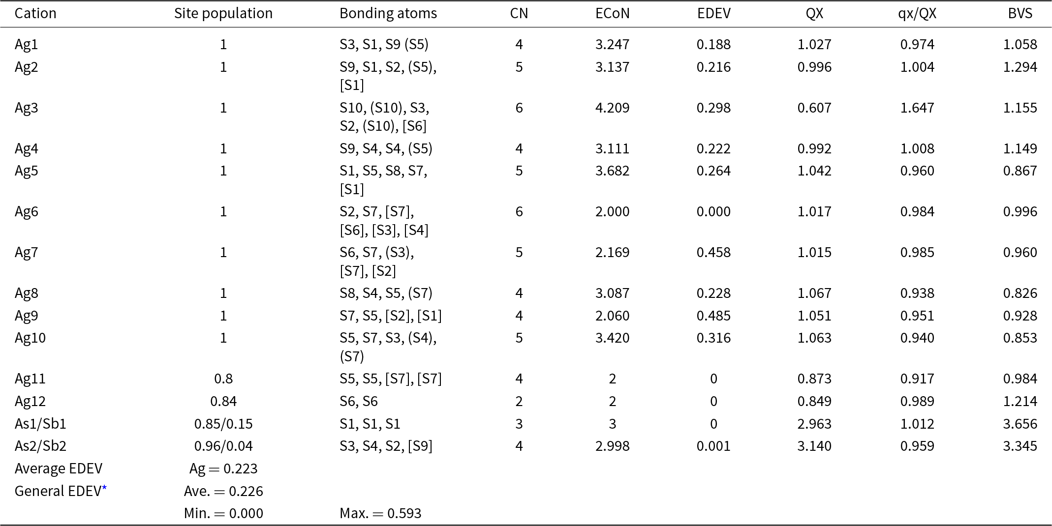
Charge-distribution analysis, bond-valence sums, ECoN and EDEV* for the structure of argentopearceite-T2ac from Mikulov

Notes: parentheses: () = contribution to the charge <0.1; [] = contribution to the charge < 0.01. CN – coordination number; ECoN – effective coordination number; EDEV – deviation of ECoN from the constrained coordination number (i.e. determined by the ligands with non-zero weight bonds concerning the charge distribution); QX – charge received by cations; qx/QX – ratio of formal charge of cation/QX; BVS – bond-valence sum – a sum of bond-valences (bond-strengths) received by the cation
* Taken from Ilinca (Reference Ilinca2022)
Crystal structure
Argentopearceite from Mikulov is trigonal, space group P321 (No. 150), with a = 14.8583(5) Å and c = 12.3038(5) Å. Thus, it is a Ag end-member of the pearceite-T2ac structure type. The crystal structure of argentopearceite contains two distinct As(Sb) sites (one of them on the three-fold axis of symmetry), twelve distinct Ag sites, and ten S positions. Ag10 is (practically) in a special position, as is S9; selected special coordinates occur also for S6, S7, and S10.
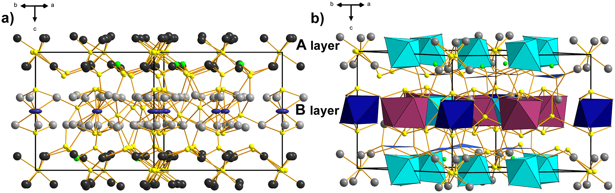
As in other pearceite–polybasite homeotypes, the crystal structure of argentopearceite is divided into two well-defined layers, called A and B (after Bindi et al., Reference Bindi, Evain and Menchetti2006), of almost identical thickness (when measured on well-populated boundary levels composed of anions), which differ, however, in the character of their cation populations. One of them is populated by As3+ and Ag (A layer) (Fig. 3a), which are placed ‘under’ the boundary sulfur sheets, with lone electron pairs of As orientated towards its more sparsely populated median sulfur sheet. The other layer lacks the lone-electron pair elements and is populated by ‘subsurface’ silver sheets. The rest of the sulfur occurs between these silver sheets, together with two characteristic cation positions, Ag11 (site occupancy Ag0.81) and Ag12 (site occupancy Ag0.66), which are in the median plane of the layer (Fig. 3a). Both positions were refined as pure silver sites, which is in agreement with the chemical analysis. This succinctly describes the distribution of atoms in the B layer; however, it contains a rich assortment of coordinations and coordination polyhedra in both layer types. Equally, it contains several cation–cation interactions and at least some signs of silver mobility.
The crystal structure of argentopearceite. (a) The view of the A and B layers. A layer: Ag – dark grey, As/Sb – green, S – yellow. B layer: Ag11 and Ag12 – dark blue, rest of Ag atoms – grey, S – yellow. (b) A layer: S9-centered Ag6S octahedra (Ag1, Ag2, Ag4) (turquoise), As/Sb in green colour, corresponding AsS3 pyramids (orientations not differentiated, blue). B layer: Ag-centred Ag12 distorted trigonal antiprisms (blue), Ag-centred Ag12 square antiprisms (plum), the interconnecting S8-centered Ag6S octahedra (3× Ag8, 3× Ag5) (light blue).

For further description, we shall use the concept of anion-centred coordination polyhedra, for the A layer in combination with the AsS3 pyramids (Fig. 3a,b). This concept yields a better-organised description of the layered architecture and its principal elements. It resembles the approach Withers et al. (Reference Withers, Norén, Welberry, Bindi, Evain and Menchetti2008) used, although it differs in definitions of some of these elements. Among other reasons, differences exist because Withers et al. (Reference Withers, Norén, Welberry, Bindi, Evain and Menchetti2008) described the pearceite Tac polytype and we deal with the T2ac polytype. Structural differences between these two polytypes (Bindi et al., Reference Bindi, Evain and Menchetti2007a) are more pronounced than typically assumed.
A layer
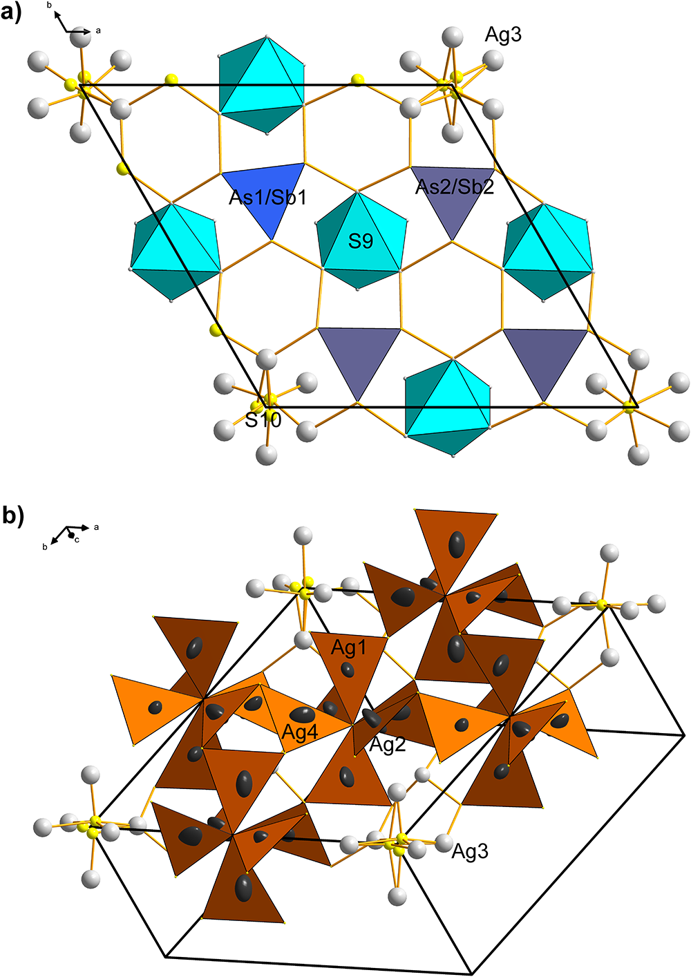
The As–Ag layer (Figs 3a,b, 4a) has all AsS3 coordination pyramids (As–S for As1 is equal to 2.231 Å; for As2 they are 2.257, 2.233 and 2.249 Å) orientated with lone-electron pairs inwards, towards its median plane, and their pyramid bases are parallel to (0001). The simplest and most important observation is that the Ag atoms present in this layer (Ag1, Ag2, and Ag4) together form octahedral Ag6 clusters, with S9 in their centres. The average of the Ag–S9 bonds is 2.474 Å. Silver, which surrounds the S9 site, forms Ag–S bonds towards the vertices of the surrounding AsS3 pyramids. A similar octahedral Ag6 configuration is formed by the (six symmetrically related) Ag3 atoms, constituting an octahedron in the 0,0,z positions. The average Ag3–S10 bond is 2.422 Å, an average of 2.168, 2.434 and 2.663 Å; distances resulting from the split character of S10.
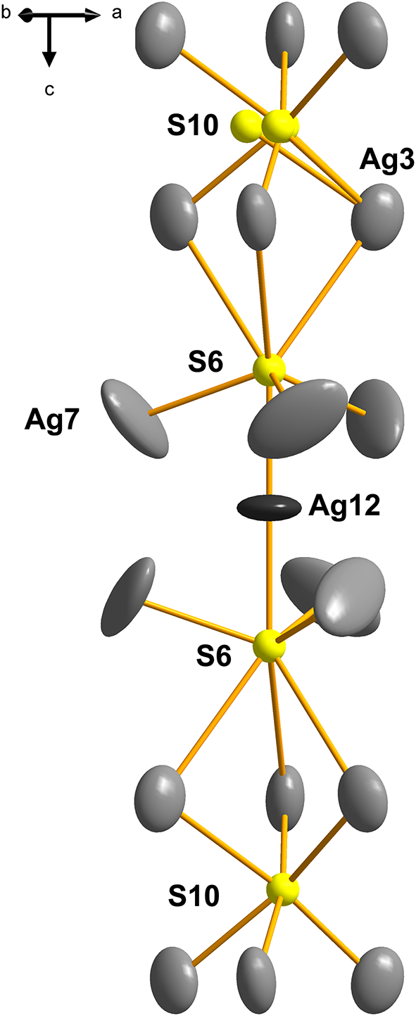
The peculiar behaviour of the S-centred Ag3–S10 cluster does not appear to result only from overall deprivation in space and might also reflect the local situation in the Ag12–S6–(Ag3)3–S10–(Ag3)3–S6 column (Fig. 5). The other Ag–S bonds (2.38–2.52 Å) are of the usual length. In the Cu-containing pearceite-Tac, Withers et al. (Reference Withers, Norén, Welberry, Bindi, Evain and Menchetti2008) assume that the positional disorder of the analogue of our S10, results from statistical (Ag, Cu) occupancies of the surrounding octahedral ligands to the central sulfur atom and subsequent satisfaction of bond valences. However, the ligands (all Ag3) were refined as pure silver in the present case. Interestingly, the Ag3–S10 configurations occur only as a minority among the other, configurationally simple types of anion-centred octahedra with S9 in their centres. In contrast, in the Tac structure, they are the only type of anion-centred octahedron in the A layer.
The alternative description of this layer is of equal crystal-chemical importance. All Ag sites (Ag1, Ag2 and Ag4) form 6-winged ‘spinners’, with the central S9 atom (Fig. 4b), as well as all peripheral S atoms, situated within their own structural (0001) A layer. They remind us of the spinners observed in the structure of tetrahedrite isotypes (Makovicky, Reference Makovicky2021). However, the orientation of AgS3 triangles is different, resulting in the (‘approximate’) spinner bar 3-symmetry. The bond to the central S9 sulfur of the spinner is, in most cases, just slightly shorter than the rest of the Ag–S bonds. The Ag–Ag distances (based on static Ag atoms) are in the range 3.02–4.10 Å, excluding the presence of cation–cation bonds in this layer, and suggesting at the same time that the above octahedral arrangements of silver atoms are a result of general crystal-chemical convenience (satisfying a triangular bonding scheme for Ag) and not of the Ag–Ag bonding. The Ag–Ag distances between spinners are 4.048 Å, and spinner arm edges (S–S distances) measure ∼3.9–4.8 Å. Spinners formed by Ag3 bear signs of the S10 splitting.
The A layer from the crystal structure of argentopearceite. (a) S9-centred SAg6 polyhedra (turquoise) and projections of the AsS3 trigonal pyramids (indigo and blue). Viewed along [0001]. (b) An alternative description of the layer: clusters of six AgS3 propellers, each sharing a central S9 atom.

A side-view of A+B layers indicates that the Ag–S bonds that interconnect the A and B layers originate at the Ag atoms in the ‘Ag-only’ B layer and not in the Ag–As layer. For example, Ag5 has a rather short bond (2.503 Å) directed to S1 from the opposing A layer.
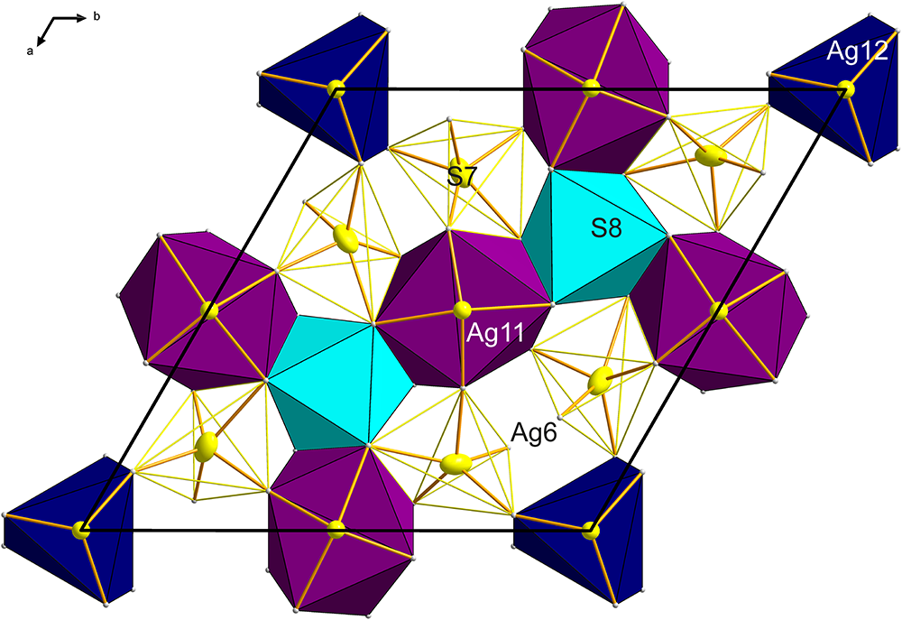
B layer
The As-free B layer can be interpreted as a mosaic of four different coordination polyhedra: two different clusters based on cation–cation bonds and two anion-centred coordination polyhedra which interconnect them (Fig. 6). This scheme of ‘inverted polyhedra’ offers the simplest description for the B layer. The cluster based on the central Ag12 atom has six Ag7 ligands at 2.696 Å and forms a distorted trigonal prism (Fig. 6). These silver atoms are separated by distances of 3.007 Å, and 2× 3.954 Å from one another. The second-nearest Ag atoms to Ag12 are the Ag8 atoms, at a distance of only 3.698 Å from the central Ag12. The Ag12 polyhedron is situated at x = y = 0 and z = 0.5. The other metal cluster is situated at (0.52,0,½) and equivalent positions. Remarkably, it is a distorted square antiprism around Ag11, with only four short cation–cation contacts, arranged according to the ‘horizontal’ two-fold rotation operation: 2× 2.742 Å to Ag10 and 2× 2.852 Å to Ag9 in the form of a disphenoid. Distances from Ag11 to the remaining antiprism corners are longer: 2.972 Å to Ag5, and 3.095 Å to Ag8.
Both cation clusters are topped by single S atoms from both the +c and –c sides. The Ag11–S5 distance is 2.307 Å, and the Ag12–S6 distance is somewhat shorter, 2.226 Å. Both these sulfurs are bonded to the cations at the top corners of the (anti)prisms. The above-mentioned Ag12-based (anti)prism is composed of only Ag7 atoms, and the topping S6–Ag7 bonds are 2.416 Å long. In the Ag11 case, the topping S5 has bond distances from 2.440 Å to 2.756 Å, in agreement with the trapezoidal form of the (0001) faces of the cluster.
Three Ag11 clusters in one B layer are separated only by an octahedral anion-centred cluster of S7, coordinated by three Ag5 and three Ag8 atoms. There are three 2.527 Å bonds S8–Ag8 and three 2.782 Å bonds to Ag5 present; the Ag5–Ag11 distance is 3.645 and 3.710 Å, whereas the Ag5–Ag5 distances are 3.547 Å and the Ag8–Ag8 distances are longer, 3.955 Å. Clearly, none of the cation–cation interaction mechanisms seen in the surrounding antiprisms ‘spill over’ into this polyhedron, and some of the Ag–S distances might even be somewhat longer, perhaps stretched by the requirements of the surrounding polyhedra.
The S7-centred polyhedron is complicated, and these polyhedra leave small unfilled gaps that stretch between adjacent Ag11- and Ag12-based polyhedra (Fig. 6). Four of the Ag ligands to S7 have Ag–S distances between 2.43 and 2.67 Å, whereas the other four have 2.83 Å to 3.45 Å. This polyhedron essentially separates the Ag11-centred clusters from the adjacent Ag12-centred clusters.
An ordered layer-to-layer match of individual configurations is observed across the layer sequence; they form a sort of columnar sequence (for instance, see Fig. 5). In the stacking arrangement inspected along the [0001] direction, the S8-centred octahedra follow one set of AsS3 pyramids; the other set of pyramids overlaps with the S7 polyhedra in a less-centred fashion. Pyramids of As2 alternate with intermediate S8-based octahedra, leaving a considerable cavity for the lone electron pair of As2 (the As2–S1 distance is 4.288 Å, As2–Ag2 is 3.559 Å, and As2–As2’ is equal to 4.840 Å). However, the pyramidal placement along the c axis and their orientation alternates. Selected centres of false As rings in the As-containing layer (i.e. the S10-centered Ag3 octahedra) overlap with the Ag11-centred trigonal (anti)prisms, whereas the S9-octahedra (Ag1, Ag2, Ag4) with the square Ag12-centred square antiprisms along the c direction. In this way, in the two latter cases, the cation–cation bonded clusters become separated from one another across the layer sequence.
The column (module) of Ag–S–Ag clusters in the structure of argentopearceite that involves a positionally disordered S10 site.

The B layer fragment from the crystal structure of argentopearceite with Ag-centred polyhedra (Ag12 trigonal prism, Ag11 square antiprism, and two types of S-centred polyhedra: S8-centred octahedron (light blue) and S7-centred irregular polyhedron with Ag6 atoms staggered oppositely to each other – faces indicated by the yellow solid lines).

Anharmonic approach to the description of atomic displacement parameters of Ag
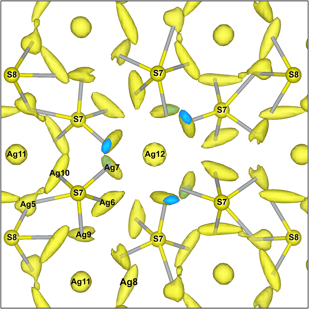
It has been well documented (Evain et al., Reference Evain, Bindi and Menchetti2006; Bindi et al., Reference Bindi, Voudouris and Spry2013, Reference Bindi, Stanley and Spry2015a, Reference Bindi, Topa and Frank2015b) that while refining the structure of pearceite–polybasite homeotypic family of minerals using the conventional harmonic approach to the atomic displacement parameters, one will obtain only incomplete information about the behaviour/motion of silver atoms as they are quite mobile in these structures at room temperature. There is always a lot of significant residual electron density in the Fourier-difference maps associated with Ag atoms using a simple harmonic refinement and this is also a valid statement for argentopearceite (6.02 e–/Å3 – harmonic vs. 3.67 e–/Å3 – anharmonic). We used up to the 3rd-order anharmonic Gram–Charlier tensors for the description of Debye-Waller factors of Ag atoms implemented in Jana2020. This approach significantly improved the model-to-data fit and a drop in R-values of ∼3%. The use of the higher orders of the Gram–Charlier development is, of course, possible, but questionable regarding the data quality and the nature of the structure (ten corresponding atoms for which the use of the higher order might be considered – a lot of correlations). Recently, we have discussed this topic in the paper describing the use of the Gram–Charlier development to refine the crystal structure of the mineral theuerdankite, Ag3(AsO4) (Plášil et al., Reference Plášil, Sejkora, Dolníček, Petříček, Désor, Majzlan, Gross, Möhn and Schürmann2024). The final R-values reached by the refinement, including the anharmonic approach to the ADPs of the Ag atoms (Fig. 7) were R 1 = 0.0773, wR 2 = 0.1340 for 6594 reflections with [I > 3σ(I) (GOF = 2.78; largest peak in difference-Fourier electron density was 1.98 e–/Å3).
Non-harmonic joint probability density functions isosurfaces of Ag atoms within the top of the B layer and adhering (interacting) atoms from the A layer in the structure of argentopearceite at room temperature. The size of the S atoms is arbitrary. The isosurface level of the 3D maps is 0.08 Å–3.

The principal conclusion about the behaviour of silver atoms in the structure of argentopearceite at room temperature is that, with the possible (questionable) exception of the Ag6, Ag9 and Ag10 sites, the displacement parameters of silver atoms indicate more or less fixed cation sites, with a degree and orientation of anisotropy following the shape of their coordination polyhedron and not just the longer occupied portions of the possible diffusion path.
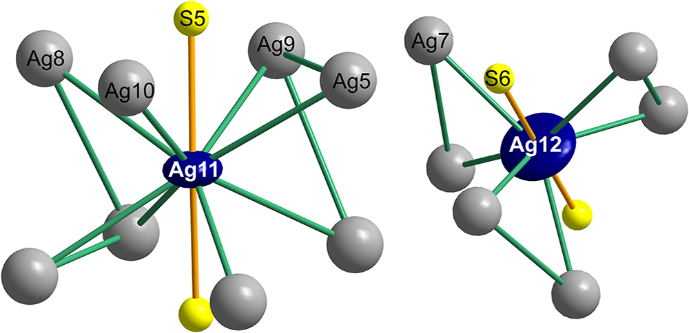
Most remarkable are the shapes of ADPs described by the joint probability density function Ag11 and Ag12. Both are very flat discs (Fig. 8) with a roughly circular outline. A disc of Ag12 is actually thinner than that of Ag11. These strange configurations combine with more pronounced displacement ellipsoids of Ag5 and Ag10 (for Ag11), and Ag6 and Ag7 (for Ag12). This is observed in all cation–cation interactions in argentopearceite. This can be explained as because the cation–cation distances are strictly maintained and, when the central Ag11 or Ag12 cation assumes different positions (shifts) in its displacement disc, the interacting Ag atoms from the above/below sub-layers have to adjust to preserve the cation–cation bond length. Moreover, both of the central cations can eventually host Cu (concerning a possible solid-solution between argentopearceite and pearceite), and analogous statistical adjustment of corresponding bonded Ag atoms to the differing Ag–Ag, Ag–Cu, as well as Ag–S and Cu–S bond lengths has to take place. That may also explain the strange shape of the Ag11 and Ag12 ADPs.
The Ag-centred clusters (Ag11 and Ag12) with cation–cation bonds and the surrounding region. Green joins between the silver atoms indicate significant cation–cation interactions.

The Ag8 and Ag10 atoms are a part of the cluster based on Ag11. They are among those with strongly developed displacement ellipsoids, which are slightly curved, suggesting a potential common free space within the structure. Such a space, perhaps, can suggest the possible diffusion of Ag at temperatures above room temperature. However, this space and character do not continue towards the remaining silver atoms on the same z level; thus, the free space does not surround the central S7 atom. The other two Ag atoms forming the top plane of the square antiprism, Ag5 and Ag9, display a lower degree of in-plane motion and differ greatly from the dynamic behaviour of Ag8 and Ag10.
Related minerals and structures
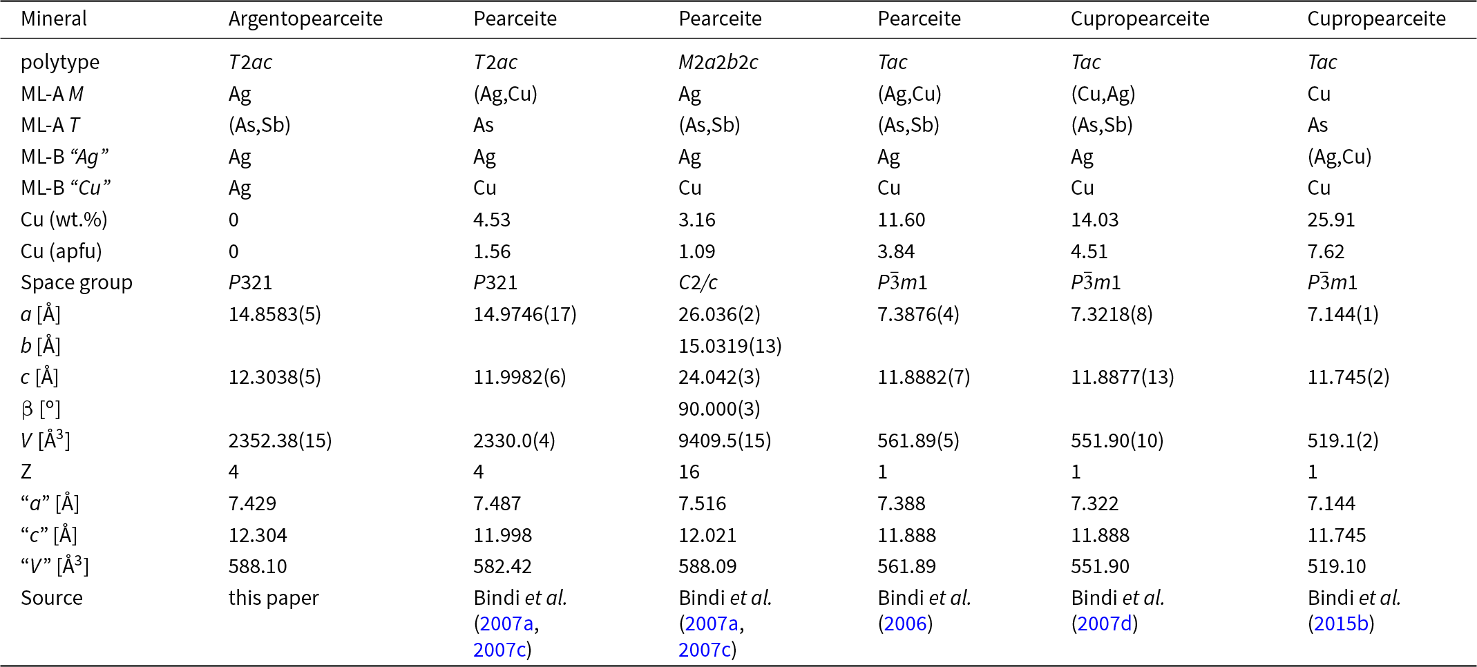
Argentopearceite does not correspond to any valid or invalid unnamed mineral (Smith and Nickel, Reference Smith and Nickel2007). It is the first approved confirmed Cu-free member of the polybasite group, Strunz class 2.GB.15. A comparison of selected data for valid members of this group is given in Table 8. The number of individual sites usually occupied by Cu in module layer B [Ag9CuS4] in polybasite-group minerals is related to the polytype: from one site at -Tac; to two at -T2ac; and three sites for -M2a2b2c. Therefore we suggest for nomenclature reasons to define simple pearceite as a mineral with Cu > 0.5 apfu and argentopearceite with Cu < 0.5 apfu. Billingsleyite, Ag7(As,Sb)S6 (Bindi et al., Reference Bindi, Downs and Menchetti2010), shows a similar chemical composition to argentopearceite but completely differs in optical properties, symmetry and crystal structure.
Comparison of As–S-dominant members of the polybasite group

Notes: ML-A: module layer A; ML-B:module layer B; “a”, “c”, “V” – parameters of the hexagonal subcell
Supplementary material
The supplementary material for this article can be found at https://doi.org/10.1180/mgm.2025.10101.
Acknowledgements
The helpful comments of Anatoly Kasatkin, an anonymous reviewer, the Associate Editor František Laufek and Principal Editor Stuart Mills are greatly appreciated.
Financial statement
This study was supported by the Ministry of Culture of the Czech Republic (long-term project DKRVO 2024-2028/1.II.c; National Museum, 00023272) for JS, PŠ and ZD. Additionally, we acknowledge the support by the CzechNanoLab Research Infrastructure supported by MEYS CR (LM2023051) for JP.
Competing interests
The authors declare none.


 Open access