


Impact Statement
Nozzles that employ the Coand effect have been widely studied and used in numerous flow control applications. However, the width-to-length aspect ratio  $W/L$ of such injectors is normally assumed to be very large, $W/L\gg 1$. Hence finite-span effects are usually neglected. Our study considers a Coand nozzle whose $W/L\approx 5.5$, for which the finite span of the nozzle plays a major role in determining its flow topology. In this paper, we explain in detail for the first time the origin of the peculiar U-shaped jet out-flowing from finite-span Coand nozzles and we characterize the robustness of its features. Our results also provide practical guidelines for the use of the nozzle. In particular, these results are intended for aeronautical applications in axial compressors. Moreover, we expect that the Coand nozzle design investigated in this paper can further contribute to enhancing flow control capabilities, as multiple such nozzles could be installed side by side either to produce a quasi-uniform large-span jet or to create a flow control array that could induce a flexible solution for time–space jet modulation.
1. Introduction
Actuator designs that exploit the Coand effect for remaining attached to a nearby wall normal to their injection axis are largely used in many aerodynamic applications. They include control of circulation in aeronautics (Reference Englar, Smith, Kelley and RoverEnglar, Smith, Kelley, & Rover, 1994a, Reference Englar, Smith, Kelley and Rover1994b; Reference Nishino, Hahn and ShariffNishino, Hahn, & Shariff, 2010; Reference Semaan, Kumar, Burnazzi, Tissot, Cordier and NoackSemaan et al., 2016), wind energy (Reference Djojodihardjo, Abdul Hamid, Jaafar, Basri, Romli, Mustapha, Rafie and Abdul MajidDjojodihardjo et al., 2013) and drag reduction of bluff bodies (Reference Barros, Borée, Noack, Spohn and RuizBarros, Borée, Noack, Spohn, & Ruiz, 2016; Reference Geropp and OdenthalGeropp & Odenthal, 2000; Reference Haffner, Borée, Spohn and CastelainHaffner, Borée, Spohn, & Castelain, 2020). The flow physics of such jets, on a convex surface, has been extensively investigated in the literature (Reference Dunaevich and GreenblattDunaevich & Greenblatt, 2020; Reference Gross and FaselGross & Fasel, 2006; Reference Neuendorf, Lourenco and WygnanskiNeuendorf, Lourenco, & Wygnanski, 2004; Reference Neuendorf and WygnanskiNeuendorf & Wygnanski, 1999) and explained as the result of streamwise Görtler-like vortices. It has to be noted that, for most of the above applications and analyses, the flow is propagating on a convex surface, and the jet has a span width  $W_{n}$ that is several orders of magnitude greater than the jet nozzle length $L_{n}$ in the streamwise direction. The side effects due to the width of such jets are thus negligible and not considered in depth in the aforementioned studies. Wall jets have also been widely investigated experimentally (Reference Eriksson, Karlsson and PerssonEriksson, Karlsson, & Persson, 1998; Reference Rostamy, Bergstrom, Sumner and BuggRostamy, Bergstrom, Sumner, & Bugg, 2011) and numerically (Reference Banyassady and PiomelliBanyassady & Piomelli, 2014, Reference Banyassady and Piomelli2015; Reference Dejoan and LeschzinerDejoan & Leschziner, 2005). More recently, a direct numerical simulation (Reference Naqavi, Tyacke and TuckerNaqavi, Tyacke, & Tucker, 2018) of such flow has been performed at $Re=7500$ (Reynolds number based on the height and jet velocity at the slot exit). It was demonstrated that the jet flow dynamics is dominated by a Kelvin–Helmholtz instability that develops in the shear layer existing between the jet and the outer flow. This generates spanwise vortices which interact with each other and leads to secondary flow instabilities. Also, in that flow configuration, the jet width is considered to be large and the side effects are negligible.
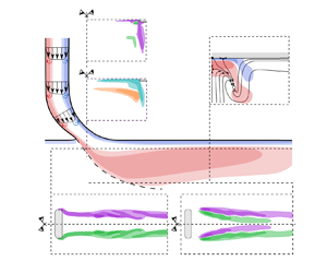
In the last two decades, active flow control with jets has been developed in axial compressors. The idea was to send a high-momentum jet that interacts with the main flow at the blade tip. The objective was to prevent or delay the flow mechanisms (Reference Hewkin-Smith, Pullan, Grimshaw, Greitzer and SpakovszkyHewkin-Smith, Pullan, Grimshaw, Greitzer, & Spakovszky, 2019; Reference Pullan, Young, Day, Greitzer and SpakovszkyPullan, Young, Day, Greitzer, & Spakovszky, 2015) leading to the arising of rotating stall and surge (Reference Li, Du, Nie and ZhangLi, Du, Nie, & Zhang, 2019) which are some of the main limitations in the performance and operating range of axial compressors (Reference DayDay, 2015). Reference Suder, Hathaway, Thorp, Strazisar and BrightSuder, Hathaway, Thorp, Strazisar, and Bright (2001), Reference Nie, Xu, Cheng and ChenNie, Xu, Cheng, and Chen (2002) and Reference Li, Lin, Tong, Nie and ChenLi, Lin, Tong, Nie, and Chen (2015) have proven that, for such applications, the best blowing direction is the one where the jet is oriented tangentially to the casing, to blow directly in the tip gap. To avoid the protrusion of the actuator, which can generate unexpected secondary flows, an interesting way to generate such kinds of wall-attached jets consists of taking advantage of the Coand effect (Reference Kern, Brehm and NiehuisKern, Brehm, & Niehuis, 2017; Reference Li, Lin, Tong, Nie and ChenLi et al., 2015; Reference Strazisar, Bright, Thorp, Culley and SuderStrazisar, Bright, Thorp, Culley, & Suder, 2004). Recent actuator designs successfully implemented the Coand effect generating control jets, in both continuous and pulsed modes. Reference Margalida, Joseph, Roussette and DazinMargalida, Joseph, Roussette, and Dazin (2021) reported and tested the design of a Coand-jet actuator, a schematic of which is depicted in figure 1. This active control system relies on 40 three-dimensionally printed injectors installed all around the casing of an axial compressor, as close as possible to the rotor leading edge (i.e. 10 mm in their set-up). Such injectors were fed by magnetic valves (Matrix 821) with a switching frequency up to 500 Hz, and the valves were connected to a complete pressure supply system, including a dedicated compressor, instrumented buffer tanks and a filtering unit. With their design, they were able to enhance the power balance (Reference Moubogha Moubogha, Margalida, Joseph, Roussette and DazinMoubogha Moubogha, Margalida, Joseph, Roussette, & Dazin, 2022) and obtain a significant stall margin improvement of their compressor (see Reference Dazin, Joseph, Romano, Gallas, Marty, Aigouy, Stôßel and NiehuisDazin et al. (2021) for more details about the control strategy).
Radial cut of an axial compressor rotating with rotation rate  $\Omega$ and equipped with active flow control system. Coand-effectinjector is detailed in the top-right corner.

When considering active flow control for energy-saving purposes, it is crucial to have a reliable knowledge of the physical properties of the flow injected by the actuators and how they evolve when the jet is propagating. It has to be noted that the jets obtained by the system described above (Reference Margalida, Joseph, Roussette and DazinMargalida et al., 2021) are rather different from those used in more classical control applications. In particular:
(i) The width-to-length ratio of the injector nozzle of Reference Margalida, Joseph, Roussette and DazinMargalida et al. (2021) is close to $5.5$ and the finite-span effects due to the order-one width-to-length ratio cannot be neglected.
(ii) Each jet propagates along the concave surface of the carter in the direction normal to the cross-section of the compressor, and the effect of the carter curvature, as well as of the interaction between injectors, is a higher-order effect that can be neglected when explaining the physics of the injection nozzle (see supplementary material available at https://doi.org/10.1017/flo.2023.9).

Consequently, to understand the flow physics of small-width injectors, an in-depth flow characterization of one actuator extracted from the compressor is reported in this study. The aim is to explain how the emerging jet is formed, to characterize its topology and to produce a performance map of the single-injector control system by quantifying the jet velocity at several cross-sections downstream of the injector outlet as a function of the mass inflow. This is done by simultaneously using experimental measurements and numerical simulations for the actual design and flow parameters proposed by Reference Margalida, Joseph, Roussette and DazinMargalida et al. (2021).
Consequently, the paper is organized as follows. After this introduction, § 2 is devoted to the formulation of the problem from a theoretical point of view. That is followed by § 3, where the numerical method and the turbulence modelling used to perform the computations are presented, with the details of the experimental measurement techniques and the experimental set-up used to investigate the jet. Section 4 presents the results, including a comparison between the experiments and the simulations. Finally, the results are discussed in § 5, and conclusions are drawn.
2. Problem formulation
The compressible air flow in the actuator is investigated under constant mass inflow conditions. The entrance of the injector consists of a vertical circular pipe of height  $H_{c}$ and cross-sectional radius $R_{c}$ that smoothly turns into a converging–diverging nozzle of height $H_{n}$ and rectangular cross-section smoothed at the corners. The actuator is flush-mounted to a rigid wall over the horizontal $(x,y)$ plane, with the injector's outflow cross-section characterized by length $L_{n}$ and width $W_{n}$. Detailed information about the design of the actuator is given in Reference Margalida, Joseph, Roussette and DazinMargalida et al. (2021).
A schematic of the problem set-up is depicted in figure 2. A strong jet is produced at the outlet of the actuator and it expands in a large domain confined below the plane wall at the  $(x,y)$ plane, either attaching on or separating at the wall. In order to mimic an unconfined domain in $y$ and $x$ directions, the bulk flow domain below the plane wall consists of a cuboidal shape symmetric with respect to the $(x,z)$ plane, with length $L$ and width $W$ taken much larger than the corresponding characteristic lengths of the actuator outflow cross-section, $L_{n}$ and $W_{n}$, respectively. The height $H$ of the box is taken large enough to approximate the outflow of a jet in a semi-infinite domain. The geometrical characterization of the problem is completed by the inlet distance $L_{in}$ between the trailing edge of the outflow cross-section of the converging–diverging nozzle and the upstream outflow boundary.
Schematic of the vertical actuator flush-mounted to a horizontal wall (solid line) expanding in a three-dimensionally semi-infinite domain. The orange boundaries are outlets, while the green boundary at the top is a mass inflow. The vertical direction is defined by the gravitational acceleration  $\boldsymbol {g}=(0, 0, -g)$. The cross-section of the domain with the plane of symmetry $(x,z)$ is depicted in grey.

The compressible continuity, momentum and total energy equations read
 \begin{gather}
\frac{\partial \rho}{\partial t} +
\boldsymbol{\nabla}\boldsymbol{\cdot}\left(\rho
\boldsymbol{u}\right) = 0,
\end{gather}
\begin{gather}
\frac{\partial \rho}{\partial t} +
\boldsymbol{\nabla}\boldsymbol{\cdot}\left(\rho
\boldsymbol{u}\right) = 0,
\end{gather} \begin{gather}\frac{\partial
\rho \boldsymbol{u}}{\partial t} +
\boldsymbol{\nabla}\boldsymbol{\cdot} \left\lbrace\rho
\boldsymbol{u} \otimes \boldsymbol{u} -
\mu\left[\boldsymbol{\nabla} \otimes \boldsymbol{u} +
\left(\boldsymbol{\nabla} \otimes \boldsymbol{u}
\right)^{\rm T} - \frac{2}{3}\left(\boldsymbol{\nabla}
\boldsymbol{\cdot}
\boldsymbol{u}\right){I}\right]\right\rbrace
+ \boldsymbol{\nabla} p = \boldsymbol{f},
\end{gather}
\begin{gather}\frac{\partial
\rho \boldsymbol{u}}{\partial t} +
\boldsymbol{\nabla}\boldsymbol{\cdot} \left\lbrace\rho
\boldsymbol{u} \otimes \boldsymbol{u} -
\mu\left[\boldsymbol{\nabla} \otimes \boldsymbol{u} +
\left(\boldsymbol{\nabla} \otimes \boldsymbol{u}
\right)^{\rm T} - \frac{2}{3}\left(\boldsymbol{\nabla}
\boldsymbol{\cdot}
\boldsymbol{u}\right){I}\right]\right\rbrace
+ \boldsymbol{\nabla} p = \boldsymbol{f},
\end{gather} \begin{gather}\frac{\partial
E}{\partial t} +
\boldsymbol{\nabla}\boldsymbol{\cdot}\left\lbrace \left(E +
p\right)\boldsymbol{u} - \mu\left[\boldsymbol{\nabla}
\otimes \boldsymbol{u} + \left(\boldsymbol{\nabla} \otimes
\boldsymbol{u} \right)^{\rm T} -
\frac{2}{3}\left(\boldsymbol{\nabla} \boldsymbol{\cdot}
\boldsymbol{u}\right){I}\right]\boldsymbol{\cdot}
\boldsymbol{u} - \kappa \boldsymbol{\nabla} T\right\rbrace
= \boldsymbol{f}\boldsymbol{\cdot}\boldsymbol{u},
\end{gather}
\begin{gather}\frac{\partial
E}{\partial t} +
\boldsymbol{\nabla}\boldsymbol{\cdot}\left\lbrace \left(E +
p\right)\boldsymbol{u} - \mu\left[\boldsymbol{\nabla}
\otimes \boldsymbol{u} + \left(\boldsymbol{\nabla} \otimes
\boldsymbol{u} \right)^{\rm T} -
\frac{2}{3}\left(\boldsymbol{\nabla} \boldsymbol{\cdot}
\boldsymbol{u}\right){I}\right]\boldsymbol{\cdot}
\boldsymbol{u} - \kappa \boldsymbol{\nabla} T\right\rbrace
= \boldsymbol{f}\boldsymbol{\cdot}\boldsymbol{u},
\end{gather}
where  $t$ and $\boldsymbol {x}=(x,y,z)$ denote the time and space coordinates, $\mu$ and $\kappa$ are the dynamic viscosity and the thermal conductivity of the fluid, assumed constant, and $\rho$, $p$,
$p$,  $T$,
$T$,  $E=\rho (\boldsymbol {u}\boldsymbol {\cdot }\boldsymbol {u}/2+e)$, $e$ and $\boldsymbol {u}=(u,v,w)$ are the density, pressure, temperature, total energy per unit volume, internal specific energy and velocity field, respectively. Finally, $\boldsymbol {f}$ includes the external volume forces, i.e. $\boldsymbol {f}=\rho \boldsymbol {g}$, where $\boldsymbol {g}=(0, 0, -g)$ is the gravitational acceleration.
In (2.1) we have assumed the constitutive equation for the shear stress tensor is Newtonian, and the modelling Stokes hypothesis is employed for relating the dynamic viscosity and the Lamé coefficient. Moreover, heat conduction  $\boldsymbol {q}$ is modelled by the Fourier law, i.e. $\boldsymbol {q}=-\kappa \boldsymbol {\nabla } T$. As a constitutive equation for the fluid, we employ the ideal gas model, which yields $e=p/[\rho (\gamma -1)]$ or, equivalently, $p = \rho \mathcal {R} T$, where $\gamma$ is the adiabatic index, assumed constant, and $\mathcal {R}$ is the specific gas constant given by the universal gas constant divided by the molar mass of the gas.
The closure of the mathematical problem defined by (2.1) is achieved by enforcing the boundary conditions. At the entry of the actuator (green in figure 2) we enforce mass-flow-rate inflow condition. No-slip boundary conditions are enforced all over the internal walls of the actuator as well as at the  $(x,y)$ plane delimited by the black solid lines in figure 2. All walls are considered adiabatic. The upstream and bottom boundaries are modelled as outflow boundaries in order to study the free jet configuration. Finally, the five remaining boundaries (coloured in orange) are outflows. All outflow boundary conditions are defined by extrapolation of the solution from the interior of the domain, including the additional constraint that there is no backflow.
3. Numerical and experimental methods
The commercial software STAR-CCM+ has been used to carry out the parametric numerical simulations reported in the body of this study. A comparison with OpenFOAM is also reported in the following. The computational box at the outlet of the actuator has dimensions  $L\times H\times W = (75 \times 35 \times 100)$ mm, the actuator is characterized by $H_{c}=27.5$, $R_{c}=2$, $H_{n}=16.5$, $L_{n}=1.8$, $W_{n}=10$ mm and the inflow length is $L_{in}=15$ mm. The choice of the dimensions for the computational box is validated in the supplementary material. For the energy equation, all the walls are assumed adiabatic and the temperature at the inflow of the injector is set to 300 K. Corresponding details of the mesh, the time discretization and the convergence of our numerical simulations are reported in the supplementary material.
Two mass flow rates (1.29 and 2.15 g s $^{-1}$) have been investigated experimentally. These values have been fixed by means of a digital flow meter in line with the inflow system of the injector. The device used in the present study is a Festo SFAH flow meter, measuring up to 200 l min $^{-1}$, with an error of ${\pm }1\,\%$ full scale and 2 % of the measured value according to the manufacturer data. The $(y,z)$ longitudinal-symmetry plane and an $(x,z)$ transverse plane at $y = -10$ mm have been investigated experimentally for the two aforementioned flow rates (see figure 3), with a spatial resolution of 0.2 mm in the $z$ direction and 0.5 mm in $x$ and $y$ directions. Position 0 on the $z$ axis corresponds to the closest location to the wall that can be monitored by our experimental apparatus, and is located at a distance of 0.3 mm from the wall, i.e. $z/W_{n}=0.03$. The transverse plane at 10 mm downstream of the jet, i.e. at $y/W_{n}= -1$, corresponds to a location of interest for flow control in turbomachinery applications (rotor leading edge in the compressor; see Reference Margalida, Joseph, Roussette and DazinMargalida et al. (2021) and Reference Moubogha Moubogha, Margalida, Joseph, Roussette and DazinMoubogha Moubogha et al. (2022) for more details).
Scheme of the location of the available experimental data. Adapted from Reference MargalidaMargalida (2019).

4. Results
4.1 Validation of the numerical simulations
This subsection only focuses on the validation of the numerical simulations by comparison with the experimental data. The analysis of the jet flow topology and dynamics is presented in the following subsection. A quantitative comparison between the numerical simulations and the experimental measurements is depicted in figures 4 and 5 for two cross-sections ( $y/W_{n}=-1$ and $x=0$) and the two mass flow rates, i.e. 1.29 and 2.15 g s $^{-1}$. The colourbar limits are adapted to the mass flow rate considered in order to facilitate the comparison between numerical and experimental results. For $\dot {m} = 2.15$ g s $^{-1}$ we set the upper limit of the velocity magnitude to 170 m s $^{-1}$ because this is the highest velocity measurable with our experimental equipment. The velocity fields predicted by the numerical simulations show a stronger enhancement of wall momentum, especially for the lowest mass flow rate (see dark red areas that saturate the upper limit of the colourbar in figures 4 and 5). This can be explained considering that the jet acceleration at the wall strongly relies on the separation region at the injector outlet (see dashed line in figure 9). Preliminary simulations have shown that the emerging shear layer is remarkably sensitive to the smoothness of the surface and to the effective radius of curvature of the injector at the upstream wall. The geometrical discrepancies between the numerical and experimental flow domains are due to technological reasons and can significantly impact the amplitude of the flow momentum injected near the wall. Thanks to dedicated simulations, we estimate that they are compatible with the minor quantitative differences we observe between our numerics and our experiments. The asymmetry of the experimental measurements at $y/W_{n}=-1$ may be due to a technological asymmetry of the injector geometry or an asymmetry of the vortical structure (Dean-vortex-like) produced by the sharp turn in the compressed air supply.
Longitudinal velocity maps for a flow rate of (a) 1.29 g s $^{-1}$ and (b) 2.15 g s $^{-1}$. The top panel depicts the result of the StarCCM+ simulations, the bottom one refers to the OpenFOAM simulations, while the middle panel reports the experimental measurements.
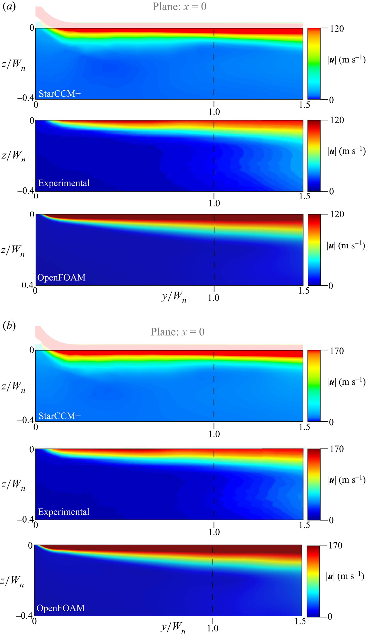
Transversal velocity maps for a flow rate of (a) 1.29 g s $^{-1}$ and (b) 2.15 g s $^{-1}$. The top panel depicts the result of the StarCCM+ simulations, the bottom one refers to the OpenFOAM simulations and the middle panel reports the experimental measurements.

Moreover, owing to the turbulence model and the numerical approximations, the arms of the U-shaped jet, which can be identified in figure 5, appear more diffuse in the StarCCM+ simulations than in the experiments. This is shown in figure 5, and further stressed by a comparison between the StarCCM+ and the OpenFOAM simulations. The grid used in OpenFOAM is described in the supplementary material, and the turbulence model of OpenFOAM is a  $k$–
$k$– $\omega$ shear stress transport, which is inherently less diffusive than the $k$–
$k$– $\epsilon$ scheme employed in the StarCCM+ simulations. As a result, the simulation results of OpenFOAM show a lower diffusion of the U-shaped jet than the simulations carried out with StarCCM+. Regardless of such differences, the StarCCM+ simulations well capture the experimental results, well characterize the flow topology and quantify the effective size of the U-shaped jet, as well as the location of the in-plane vortex cores located at $x/W_{n}\approx \pm 0.3$ (see figure 5). Hence, based on the comparison between the numerical simulations (top and bottom panels in figures 4 and 5) and the experimental results (middle panels in figures 4 and 5), we can conclude that our simulations well compare with the experiments, and they reliably reproduce the main flow features needed to understand the flow physics of the jet.
4.2 Characterization of the flow field
The two mass flow rates considered in the experimental run give rise to a stationary jet attached to the flat plate where the injector is flush-mounted. The radial acceleration of the flow at the exit of the injector is therefore always sufficient to produce a corresponding negative pressure gradient capable of robustly sustaining the Coand effect for  $\dot {m}=1.29$ and 2.15 g s $^{-1}$. This jet characteristic is confirmed by the numerical simulations, carried out for the same mass flow rates used in the experiments. This is also the case of a third flow rate of interest in our turbomachinery application, i.e. $\dot {m}=0.43$ g s $^{-1}$ (see Reference Margalida, Joseph, Roussette and DazinMargalida et al., 2021), and here investigated numerically. The inflow Reynolds and Mach numbers corresponding to three such flow rates are reported in table 1.
Dimensionless groups characteristic of the inlet jet flow condition for  $\dot {m}=0.43$, 1.29 and 2.15 g s $^{-1}$, i.e. Reynolds number ${Re}=\dot {m}/{\rm \pi} R_{c}\mu$ and Mach number ${Ma}=\dot {m}/\rho {\rm \pi}R_{c}^2\sqrt {\gamma \mathcal {R} T}$. The nominal conditions at 25 $^\circ$C are considered for $\mu$, $\rho$ and $T$.
$T$.

Figure 6 shows the velocity magnitude computed numerically over the longitudinal cross-section at  $x=0$ and the transverse cross-sections at $y/W_{n} = 0$, $-0.25$, $-0.5$, $-0.75$ and $-1$, together with the $Q$-criterion computed from the outlet of the injector. Focusing on the injection of momentum near the wall, the high-speed region is always localized near the wall within a thickness of $t_{j}/W_{n}=0.1$ from the flat plate. Moreover, a characteristic pair of counter-rotating vortices emerges downstream of the injector owing to the sharp expansion due to the geometrical transition between the actuator outlet and the outflow domain below the flat plate. This is well in agreement with the U-shaped velocity magnitude field found in the experiments (see figure 3 for a qualitative comparison and § 4.1 for a quantitative one). The resulting jet has an effective width $W_{j}$ of about $W_{j}/W_{n}=0.8$ to $0.9$, which is shorter than $W_{n}$ at the outlet of the nozzle. The narrower cross-section of the jet is a direct consequence of the two strong counter-rotating vortices that tend to lift the flow away from the wall and promote a separation over the flat plate. The width of such a separated region at the wall is about 40 % to 60 % of $W_{n}$, which is compatible with the observed jet width as the resulting shear layer rapidly expands in the spanwise direction reaching about 80 % to 90 % of $W_{n}$ at distance $\Delta z/W_{n} = 0.03$ from the flat plate (i.e. at $z=0$). This is demonstrated in figure 7, where the vector projection of the velocity on the plane at $y/W_{n}=-1$ is depicted, together with two colour maps: the vertical velocity component $w$ (left-hand panels) and the magnitude of the velocity projection (i.e. $\vert \boldsymbol {u}_{2D}\vert = \sqrt {u^2 + w^2}$, right-hand panels) for $\dot {m}=0.43$, 1.29 and 2.15 g s $^{-1}$. The topology of the projection flow is qualitatively robust upon a change in the flow rate and it revolves around three kinds of critical points, as shown in figure 7: (i) a source at the intersection between the wall and the mirror-symmetric plane (pink-enclosed black circle), (ii) two free mirror-symmetric sinks (pink-enclosed white circles) and (iii) three saddle points (pink circles), two of which are mirror-symmetrically placed along the wall (separation points) and the third one of which is located on the mirror-symmetric plane and detached from the wall. The distance between the separation points varies non-monotonically with the flow rate. It increases between $\dot {m}=0.43$ and 1.29 g s $^{-1}$, and decreases between $\dot {m}=1.29$ and 2.15 g s $^{-1}$, passing from $\approx$30 % to 60 % of $W_{n}$ and finally to $\approx$40 % of $W_{n}$. On the contrary, the mutual distance between the two free sinks does not change significantly upon variation of $\dot {m}$. This explains why the effective dimension of the resulting jet remains at $\approx$80 % to 90 % of $W_{n}$ whatever the value of the flow rate.
Left: magnitude velocity maps at  $x=0$, $y/W_{n} = 0$, $-0.25$, $-0.5$, $-0.75$, $-1$. Right: isosurfaces of the $Q$-criterion for $Q=-10^{6}$ (light blue) and $Q=10^{6}$ (dark blue). Flow rate of (a) $\dot {m}= 0.43$ g s $^{-1}$, (b) $\dot {m}= 1.29$ g s $^{-1}$ and (c) $\dot {m}= 2.15$ g s $^{-1}$. The magenta lines are guides for the eyes at $x/W_{n}=\pm 1/2$ (solid lines) and at $z/W_{n}=- 1/10$ (dashed lines).

Arrows: projection of the velocity vector field. Left: vertical velocity component  $w$. Right: magnitude of the velocity projection, $\vert \boldsymbol {u}_{2D}\vert = \sqrt {u^2 + w^2}$. All the data are considered for a cross-section at $y/W_{n}=-1$ for (a) $\dot {m}=0.43$ g s $^{-1}$, (b) $\dot {m}=1.29$ g s $^{-1}$ and (c) $\dot {m}=2.15$ g s $^{-1}$.

Considering the smooth evolution of the mean flow field downstream of the injector outlet, a deeper understanding of the characteristic critical points’ location as a function of the mass flow rate can be achieved thanks to the vorticity field. Figure 8 shows the three vorticity components  $(\omega _x,\omega _y,\omega _z)$ for the three flow rates considered, i.e. (left) $\dot {m}=0.43$ g s $^{-1}$, (middle) $\dot {m}=1.29$ g s $^{-1}$ and (right) $\dot {m}=2.15$ g s $^{-1}$. Focusing on the cross-section at $y/W_{n}=-1$, the mutual distance between the symmetric saddle points is significantly influenced by $\dot {m}$ and can be interpreted in terms of $\omega _y$ and $\omega _z$. Focusing on the separation points (see open markers at the wall in figure 7), the positive (yellow) $\omega _y$ at $x>0$ and the negative (cyan) $\omega _y$ at $x<0$ pull the separation points away from the mirror-symmetric plane $x=0$, hence away from each other. On the other hand, the positive (violet) $\omega _z$ at $x>0$ and the negative (green) $\omega _z$ at $x<0$ push such saddle points at the wall towards each other. The location of the separation points at the wall is, therefore, the result of two opposing effects: $\omega _y$ that tends to make the wall saddles diverge mirror-symmetrically with respect to each other and $\omega _z$ that makes them converge towards the source point (pink-enclosed black circle in figure 7). The short distance between the two separation points for $\dot {m}=0.43$ g s $^{-1}$ is therefore understood as an integral dominant contribution of $\omega _z$ over $\omega _y$ (confirmed by the left-hand panel of figure 7b). Upon an increase of the flow rate, all the vorticity components grow in amplitude, with $\omega _y$ growing faster with $\dot {m}$ than $\omega _z$ (cf. left-hand and middle panels of figure 8). This explains why we observe a larger distance between the separation points at the wall for $\dot {m}=1.29$ g s $^{-1}$. As we further increase the flow rate, the production mechanism of $\omega _y$ tends to saturate, while $\omega _z$ keeps increasing with $\dot {m}$ (cf. middle and right-hand panels of figure 8). As a result, the saddle points at the wall get closer once again for $\dot {m}=2.15$ g s $^{-1}$ (cf. figure 7b,c).
Map of vorticity components on the cross-sections at (a)  $y=0$ and (b) $y/W_{n}=-1$. Three flow rates are compared: (left) $\dot {m}=0.43$ g s $^{-1}$, (middle) $\dot {m}=1.29$ g s $^{-1}$ and (right) $\dot {m}=2.15$ g s $^{-1}$.

Figure 7 shows the negligible vertical displacement of the saddle point on the mirror-symmetric plane (i.e. at  $x=0$, $y/W_{n} = -1$ and $z/W_{n} \approx -0.1$) upon an increase of the mass flow rate. The vertical location of such an in-plane saddle is well understood by considering principally $\omega _x$. In fact, as observed in figure 8, an increase in the mass flow rate produces an intensification of the vorticity but does not significantly change the relative interplay between the negative (blue) and the positive (red) spanwise vorticity regions. We further stress that the induced velocity due to $\omega _y$ is mainly due to the positive (orange) and negative (cyan) regions centred at $z/W_{n}\approx -0.25$, which amplifies the towards-wall-induced velocity contribution due to the positive $\omega _x$ (red).
Finally, the location of the two mirror-symmetric free sinks (pink-enclosed white circles) can be understood by taking into account all three components of the vorticity field. The horizontal location of the sinks must result from the competition between  $\omega _y$ and $\omega _z$. However, as the sign changes of $\omega _y$ and $\omega _z$ must correlate with the free separation line departing from the saddle point at $x=0$ and $z/W_{n}\approx -0.1$ and ending in the sink at $x/W_{n}\approx \pm 0.25$ to $\pm 0.3$ and $z/W_{n}\approx -0.25$, the amplitude growth of the vorticity quasi-proportional to the flow rate leads to a weak change of the integral contribution of $\omega _y$ and $\omega _z$ on the horizontal location of the sinks. This results in a trend qualitatively equal to the horizontal attraction/repulsion of the separation points on the wall, but with a much lesser variance over the average location of the sinks. Hence, their mutual distance is $\approx$50 % of $W_{n}$ for $\dot {m}=0.43$ g s $^{-1}$, it grows to ${\approx }60\,\%$ of $W_{n}$ for $\dot {m}=1.29$ g s $^{-1}$ and it finally decreases up to ${\approx }55\,\%$ of $W_{n}$ for $\dot {m}=2.15$ g s $^{-1}$. The vertical location of the mirror-symmetric sinks can be understood by the same argument on $\omega _x$ and $\omega _y$ used for the vertical location of the saddle point at $x=0$.
A summary of the intricate flow topology and its correlation with the most significant vorticity components is sketched in figure 9(a). The black arrows in figure 9(a) denote either the velocity profiles along the injector cross-section or the projected flow direction on the transverse cross-section at  $y/W_{n}=-1$. The red and blue arrows are used to denote the sign of $\omega _x$ associated with the boundary layer inside the injector. The colour coding of the vorticity used in figure 8 is here preserved, the cross-plane source is denoted by a black circle, the mirror-symmetric sinks are shown by an open circle, while the saddle points are shown by filled semicircles. The flags are used to denote the symmetries of the flow, and the grey zones show either a wall or the outlet cross-section of the injector (see two sketches of $\omega _z$ at the bottom). Figure 9(a) demonstrates how the characteristic U-shaped jet forms out of the injector. Owing to the sharp change of cross-section at the outlet, the jet flow separates over the upstream surface of the injector outflow. As for the Coand effect, the curvature induced by the shear layer (see the dashed line on the plane at $x=0$) on the streamlines leads to a reattachment of the separated region towards the wall. This generates a peculiar two-layer structure of the vorticity near the wall, with negative spanwise vorticity (blue) all over the wall, and positive one (red) wrapped inside the region at $\omega _x<0$. The U-shaped two-layer field of $\omega _x$ is an unstable structure opposed by the negative outer layer that would tend to flatten towards the wall and the positive inner $\omega _x$ that rather tends to concentrate towards the symmetry plane. This will finally lead the U-shaped jet to redistribute into a flat narrower layer of negative $\omega _x$ at the wall and a diffuse merged vortical tube with positive spanwise vorticity on top of it. The horizontal size of the U-shape profile, as discussed above, is strongly related to the other two velocity components, generated as end vortices at the lateral surfaces of the injector outlet (see bottom-left sketch for $\omega _z$). The two-layer structure observed for $\omega _x$ is produced by the same mechanism that leads to $\omega _y$ and $\omega _z$, and it contributes to the folding of the jet on itself, as is demonstrated in § 4.3. Figure 9(b) sketches the three distinct types of structures identified by the $Q$-criterion isosurfaces depicted in figure 6. The two vorticity sheets denoted by blue and red arrows in the right-hand panel of figure 9(b) are connected along the highest-vorticity-magnitude line (dashed). The two vorticity sheets are well identified by the light-blue and dark-blue isosurfaces of $Q$ sketched near the flat plate (grey). The light-blue structure in the left-hand panel of figure 9(b) corresponds to the negative $\omega _x$ in figure 9(a), and it is attached to the wall. The two side structures depicted in the left-hand panel of figure 9(b) are two sequences of attached eddies vertically emerging from the wall which then merge to the two corresponding shear vortices along the $y$ direction. This couple of shear vortices is due to the two shear layers generated by $\omega _z$ far from the flat wall (see bottom-right panel of figure 9a).
(a) Sketch of the most relevant vorticity components and of the flow topology generated by the injector. (b) Sketch of the two vorticity sheets and of the vortical structures identified by the  $Q$-criterion.

We further point out that the specific features of our small-width Coand jets do not rely on the temperature, pressure and density fields. In fact: (i) static temperature is dominated by convective cooling, (ii) static pressure is due to either Venturi effects in the injector or the classic Coand effect at the immediate outflow and (iii) buoyancy effects are a negligible correction to inertial terms in the momentum equation (see supplementary material).
4.3 Robustness of the flow topology to flow rate variations
The effect of the mass flow rate injected in the actuator is investigated by varying  $\dot {m}\in [0.4, 2.0]$ g s $^{-1}$. The corresponding nominal Reynolds and Mach numbers range in the interval ${Re}\in [3516, 17\,581]$ and
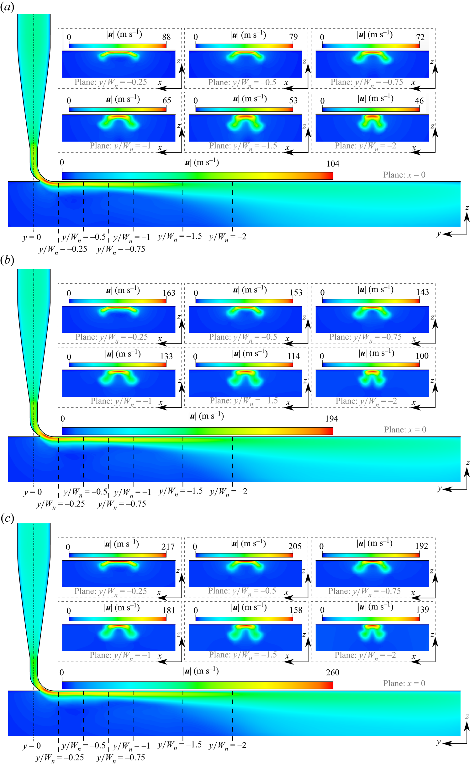
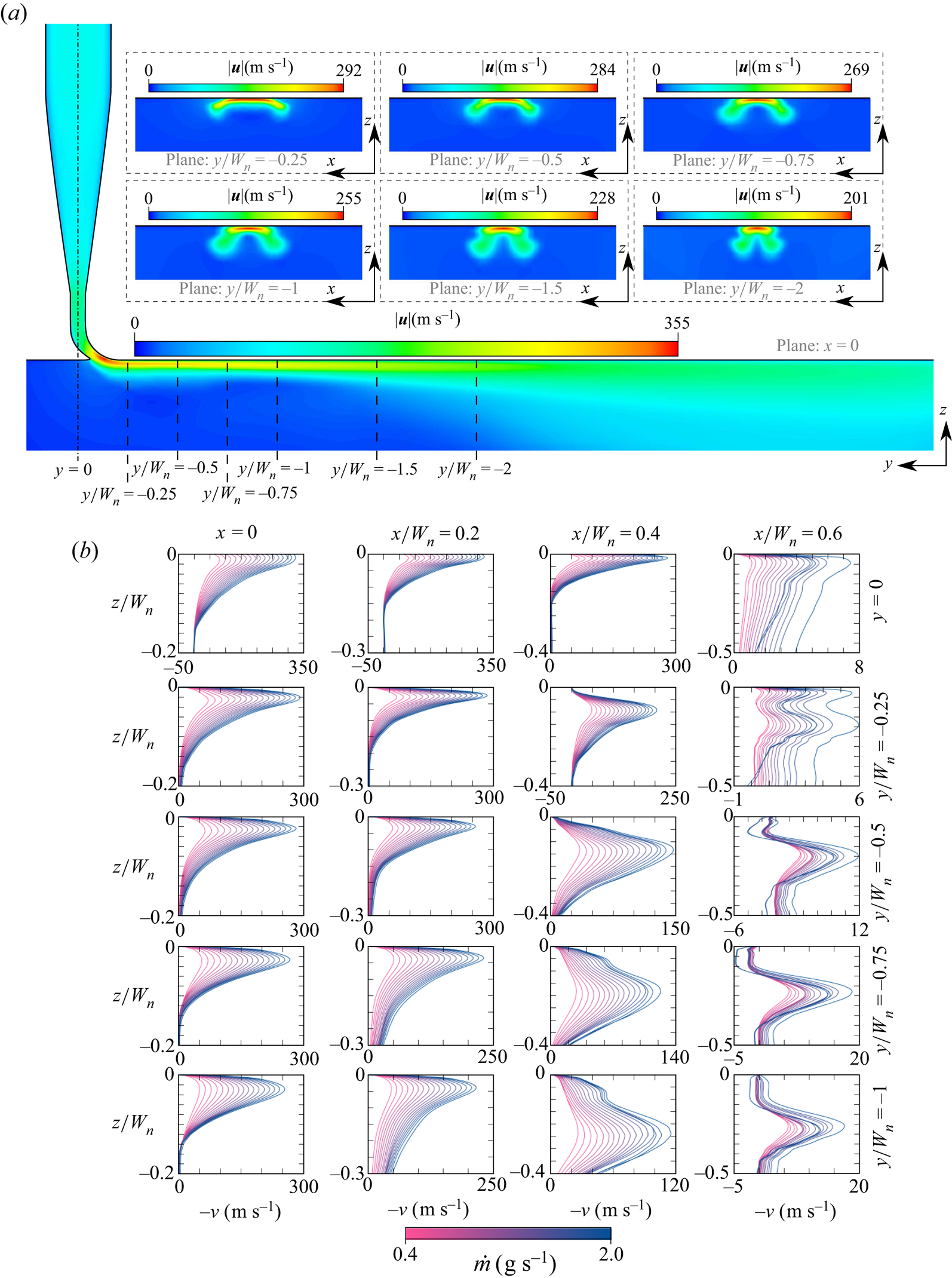
  ${Ma}\in [0.076, 0.381]$. We observe a qualitatively robust topology of the flow all over the range of mass flows considered, as demonstrated in figures 10 and 11. The longitudinal cross-section shows a smooth enhancement of near-wall velocity with $\dot {m}$. Moreover, as depicted in figure 11(b), the momentum injected near the wall is always confined to about $x/W_{n}=\pm 0.4$ (see the low velocities for $x/W_{n}=0.6$). A characteristic development of the U-shaped jet along the streamwise direction is depicted by the velocity magnitude maps on the cross-sections at $y/W_{n}=0$, $-0.25$, $-0.5$, $-0.75$, $-1$,
$-1$,  $-1.5$ and $-2$. As discussed in § 4.2, the two-layer configuration for $\omega _x$ is unstable and the inner layer tends to fold on itself upon an increase of $y$, while the outer layer flattens over the wall. This is the case for all the mass flow rates considered in this study.
Velocity magnitude for (a)  $\dot {m}= 0.5$ g s $^{-1}$, (b) $\dot {m}= 1$ g s $^{-1}$ and (c) $\dot {m}= 1.5$ g s $^{-1}$.
(a) Velocity magnitude for  $\dot {m}= 2.0$ g s $^{-1}$. (b) Streamwise velocity profiles at $y/W_{n}=0$, $-0.25$, $-0.5$, $-0.75$ and $-1$ and $x/W_{n}=0$, $0.2$, $0.4$ and $0.6$ for $\dot {m}\in [0.4, 2]$ g s $^{-1}$.
5. Discussion and conclusions
Numerical simulations of small-width wall-attached jets generated by a Coand nozzle were conducted on a large range of flow rates ( $\dot {m}\in [0.4, 2.15]$ g s $^{-1}$). The numerical results were validated by comparison with experimental data obtained by hot-wire anemometry performed for two different flow rates. The comparison of numerical simulations and experimental measurements has validated the ability of our simulations to qualitatively and quantitatively reproduce the main features of the flow under consideration.
The jet produced by the small-width Coand nozzle is clearly influenced not only by a strong two-layer spanwise vorticity structure, as is usually observed in wall jets, but also by a vorticity component normal to the wall and originated in the shear layer developing on the jet sides. We moreover revealed a two-vorticity-layer structure that emerges as a result of the separation of the flow on the upstream wall of the injector. The interactions of these vorticity components lead to a folding of the jet on itself and to a peculiar U-shape. These flow features are preserved for all the considered flow rates and their dynamics has been analysed in detail in this paper.
In terms of applications, and especially for flow control in axial compressors for which a high-momentum jet close to the wall is needed, the conclusions are mixed. On the one hand, in spite of the lift-up of the jet on its sides, a great part of the flow remains confined close to the wall with high momentum values in a region of thickness  $t_{j}/W_{n}<0.1$. This is particularly true at a distance of $y/W_{n} = -1$ targeted for applications. On the other hand, the jet is narrower than the nozzle width at its outflow ( $W_{j}/W_{n}=0.8$ to $0.9$ at $y/W_{n} = 0$) and tends to get even narrower upon an increase of the distance from the nozzle ( $W_{j}/W_{n}=0.6$ at $y/W_{n} = -1$). This is due to both the sharp expansion experienced by the flow at the nozzle outflow and the flow dynamics downstream of the actuator. Even if this is an unwanted feature for active flow control applications, the narrow span of the jet is a robust characteristic of the investigated injectors and it seems difficult to avoid. This encourages placing the actuators as close as possible to the area where they must act, which is consistent with the experimental observations of the applications available in the literature. We further stress that applications of such small-width Coand jets in axial compressors like the one of Reference Margalida, Joseph, Roussette and DazinMargalida et al. (2021) require a thorough consideration of the injection angle, the stagger angle of the rotor blades and the rotation rate at which the compressor is operated. Future works will be focused on these parameters, and how optimal control must consider their interaction.
Finally, the injector investigated in this study will further be considered in future works as it grants the chance to control the near-wall flow keeping confined the jet span. Hence, multiple such nozzles could be employed side by side to exploit their mutual interactions and produce a spanwise modulation of the resulting Coand jet front. Moreover, time and space modulations could be combined to produce a pulsating modulated Coand jet front for control of the boundary layer.
Supplementary material
Supplementary material is available at https://doi.org/10.1017/flo.2023.9.
Acknowledgements
The authors acknowledge the use of the Cassiopee Arts et Métiers Institute of Technology HPC Center made available for conducting part of the research reported in this paper.
Funding
This paper is supported by the Clean Sky European Union's Horizon 2020 research and innovation programme under grant agreement no. 886352, project ACONIT. We gratefully acknowledge the GENCI (Grand Equipement National de Calcul Intensif) for the numerical resources granted to conduct this study under the project A0102A01741.
Declaration of interests
The authors declare no conflict of interest.
Author contributions
P.J., A.D. and F.R. coordinated the project, O.E.M., X.C., C.P. and F.R. carried out the numerical simulations, J.D. and P.J. carried out the experiments and O.E.M., P.J., A.D. and F.R. wrote the manuscript.
Data availability statement
Raw data are available from the corresponding author (F.R.) upon reasonable request.
Ethical standards
The research meets all ethical guidelines, including adherence to the legal requirements of the study country.


 Open access