


Introduction
High-resolution images of the Martian surface have revealed several geological features in the 40–60° latitude bands that exhibit detailed patterns consistent with the deformation of a soft material (e.g. Squyres, Reference Squyres1979; Head and others, Reference Head, Marchant, Dickson, Kress and Baker2010). These features, referred to as viscous flow features (VFFs) (Souness and others, Reference Souness, Hubbard, Milliken and Quincey2012), are often situated on the slopes of high-relief landscapes (Milliken and others, Reference Milliken, Mustard and Goldsby2003). Visually, they share characteristics with terrestrial debris-covered glaciers or rock glaciers. VFFs are divided into several sub-types, including glacier-like forms (GLFs), lobate debris aprons (LDAs), concentric crater fills (CCFs) and lineated valley fills (LVFs) (e.g. Levy and others, Reference Levy, Fassett, Head, Schwartz and Watters2014; Souness and others, Reference Souness, Hubbard, Milliken and Quincey2012). A study by Levy and others (Reference Levy, Fassett, Head, Schwartz and Watters2014) mapped over 11000 VFFs in the mid-latitude bands, and more than 1300 GLFs have been identified by Souness and others (Reference Souness, Hubbard, Milliken and Quincey2012). Radar sounding measurements by the SHARAD (SHAllow RADar, see Seu and others, Reference Seu2007) instrument on the Mars Reconnaissance Orbiter has proven that LDA deposits mainly consist of water ice with less than 10% lithic content (Holt and others, Reference Holt2008; Plaut and others, Reference Plaut2009), and the composition of other VFFs is likely to be similar.
It is commonly assumed that the VFFs formed during different climatic conditions, since ice is currently not stable at the surface in the mid-latitudes (Mellon and Jakosky, Reference Mellon and Jakosky1995). The VFFs have likely survived due to a thin debris cover which has protected them from sublimation (e.g. Fastook and others, Reference Fastook, Head and Marchant2014). The thickness of the debris cover of LDAs is likely between 1 m (Feldman, Reference Feldman2004) and 10 m (Holt and others, Reference Holt2008), which is small relative to the ice deposit thickness. The Martian climate undergoes substantial changes on timescales of 10 s of kyrs due to fluctuations in orbital parameters, such as obliquity changes (Laskar and others, Reference Laskar, Levrard and Mustard2002). Studies suggest that GLF deposits are 0.5–10 Myrs (e.g. Garvin and others, Reference Garvin, Head, Marchant and Kreslavsky2006; Souness and others, Reference Souness, Hubbard, Milliken and Quincey2012; Hubbard and others, Reference Hubbard, Souness and Brough2014), while LVF and LDA deposits are likely much older, from tens to hundreds of Myrs old (e.g. Mangold, Reference Mangold2003; Baker and others, Reference Baker, Head and Marchant2010; Berman and others, Reference Berman, Crown and Joseph2015). This is consistent with the hypothesis that during periods of high obliquity, water ice became unstable at the poles and migrated to the mid-latitudes, which led to the formation of VFFs (Head and others, Reference Head, Mustard, Kreslavsky, Milliken and Marchant2003).
The shape and topography of VFFs contain information on their formation process and past flow history (e.g. Karlsson and others, Reference Karlsson, Schmidt and Hvidberg2015; Brough and others, Reference Brough, Hubbard and Hubbard2016). Previous studies have used similar assumptions to infer surface mass-balance patterns and flow history of the north polar layered deposits (NPLD) (Winebrenner and others, Reference Winebrenner2008; Koutnik and others, Reference Koutnik, Waddington and Winebrenner2009), but whether the NPLD has a flow history has been heavily debated (e.g. Byrne, Reference Byrne2009). For example, Karlsson and others (Reference Karlsson, Holt and Hindmarsh2011) showed that the internal stratigraphy of the deposit, derived from SHARAD observations, is inconsistent with an ice sheet that has undergone significant flow. However, it is expected that local topographic features, such as troughs, craters and scarps, may be shaped by ice flow. For example, Pathare and Paige (Reference Pathare and Paige2005) found that the dominant mechanism controlling NPLD trough morphology may be flow of subsurface ice, while Sori and others (Reference Sori, Byrne, Hamilton and Landis2016) found that scarps at the NPLD margins could experience significant viscous flow. In a similar study, Pathare and others (Reference Pathare, Paige and Turtle2005) found that the distribution and depth of craters on the south polar layered deposit is most likely controlled by viscous flow, although the effect of viscous flow may be smaller for craters on the NPLD.
In this study, we investigate the deformational properties of a well-surveyed LDA surrounding Euripus Mons in the southern hemisphere of Mars. We estimate the value of the creep exponent n as well as the accumulation rate and temperature regime. Our technique derives the basal topography below the ice deposit assuming steady-state accumulation rate along a 1-D flowline using a non-linear flow law for ice. We rely on a high-resolution digital elevation model (DEM) of the surface and a reconstructed bedrock created using SHARAD radar measurements and the topography of the surrounding area. The DEM was constructed from the High Resolution Stereo Camera (HRSC) (Gwinner and others, Reference Gwinner2010) equipped on Mars Express and has a horizontal resolution of 70 m. This is a significant improvement compared with the MOLA DTM grid spacing (~150 m at our study site). In addition, Gwinner and others (Reference Gwinner2010) demonstrated that the vertical accuracy of the HRSC DEM achieved 11.2 m error level compared to MOLA once sophisticated sensor calibration and sub-pixel image matching are applied.
Study area and data
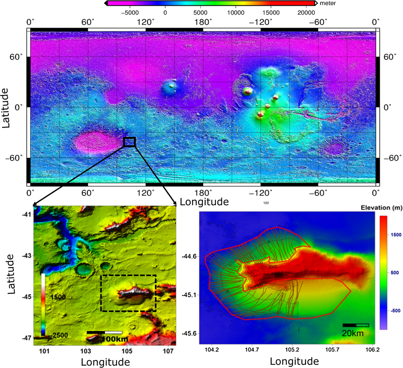
The selected study area is located at 105°E, 45°S (cf. Fig. 1). This area has several LDAs surrounding massifs, and on optical imagery the extents of the individual LDAs are clear. A high-resolution (70 m) HRSC DEM of part of the area, see Figure 2, was constructed by an effort employing an innovative photogrammetric adjustment procedure, i.e. sequential photogrammetric adjustment procedure and the densification of stereo intersection points as described in Gwinner and others (Reference Gwinner2010). It should be noted that the merits of HRSC DTM is not only in horizontal resolution but also its high-performance geodetic control which demonstrated 24 m height difference and 34 m standard deviation compared with MOLA (Gwinner and others, Reference Gwinner2010). The use of HRSC DTM should greatly reduce potential underestimation of local topographic slope of MOLA DTM, which can have up to a 30-40% error rate as proven in Kim and Muller (Reference Kim and Muller2009). The topographic slope underestimation by MOLA DTM was caused by two reasons according to the study by Kim and Muller (Reference Kim and Muller2009) employing Context Camera (CTX) and High Resolution Imaging Science Experiment (HIRISE) stereo DTMs; (1) the long sampling distances of MOLA observations especially in across track direction downgraded the vertical resolutions in the valuation model and occasionally skip locally populated steep surfaces in their measurements, (2) the big footprint size of MOLA spot which is 150 m and corresponding to several HRSC stereo measurements largely impaired the accuracy of vertical topographic measurements as stated in Gardner (Reference Gardner1992). Thus the employment of HRSC DTM in our study was justified together with its proven geodetic control. This allows for the xtraction of high-resolution measurements of the slope along estimated flow lines.
Top: MOLA global topography with the location of the LDA marked with a rectangle. The elevation is relative to the areoid and the map uses a simple cylindrical projection. Bottom left: topography map of the area containing the LDA. The box shows the location of the bottom right figure. Bottom right: elevation of the LDA from MOLA (colours) and HRSC (black contours). The LDA is outlined with a dotted red line and used flowlines are marked with red solid lines.
(a) HRSC elevation map of the investigated area in colours and contoured in grey and black, with SHARAD lines in stipled black, and (b) the reconstructed bedrock topography where the grey contours correspond to the HRSC topography in (a).
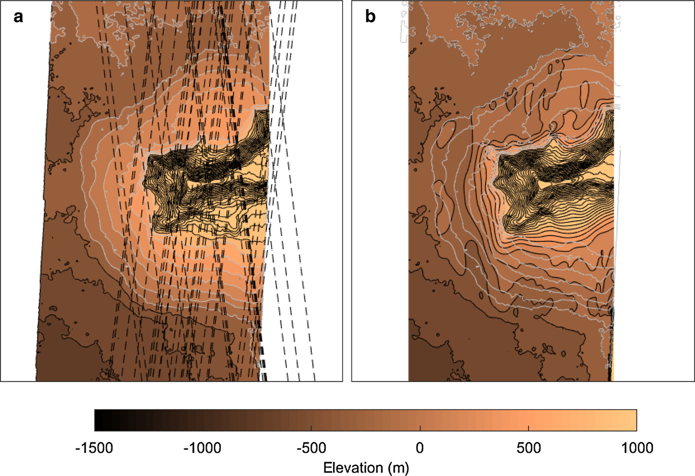
The area has been extensively surveyed by SHARAD, thus detailed information on the ice thickness can be reconstructed. The SHARAD dataset consists of 120 Reduced Data Records and was gathered using the Mars Orbital Data Explorer on the Planetary Data System Geosciences Node. The radar lines can be seen in Figure 2a.
Methods
Our methods rely on existing works on ice deformation. Experimentally, deformation of ice occurs due to several mechanisms that depend on temperature, stress and fabric, where each mechanism has different values of the creep exponent n (e.g. Duval and others, Reference Duval, Ashby and Anderman1983). In terrestrial glaciology, much work has gone into determining a single value of n which is appropriate for flow modelling of glaciers and ice sheets. This has been done through laboratory experiments (e.g. Glen, Reference Glen1955; Goldsby and Kohlstedt, Reference Goldsby and Kohlstedt2001) and field measurements (e.g. Paterson, Reference Paterson1977). The conventional value in terrestrial glaciology is n=3 (Cuffey and Paterson, Reference Cuffey and Paterson2010), but laboratory and field methods suggest values between 1 and 4, and an appropriate value of n is still being debated (e.g. Bons and others, Reference Bons2018). Even if the features on Mars consist of pure water ice, different values of n may be needed to approximate the flow of Martian ice compared to ice on Earth. This is both due to Mars' lower gravity and the possible different shapes of Martian features, which means that the ice experiences different states of stress. Thus the relative importance of the different deformation mechanisms may differ from those of terrestrial glaciers.
Flow models of varying complexity have previously been successfully applied to Martian VFFs. For example, Fastook and others (Reference Fastook, Head and Marchant2014) used a one-dimensional shallow-ice-flow model based on Glen's flow law (Glen, Reference Glen1955) to study the formation of LDAs assuming they are remnant features of a regional ice mass. Parsons and Holt (Reference Parsons and Holt2016) studied the build-up of an LDA by ice accumulation using a deformation law following Goldsby and Kohlstedt (Reference Goldsby and Kohlstedt2001). Here, we apply an approach similar to that of Karlsson and others (Reference Karlsson, Schmidt and Hvidberg2015) where the ice deformation is modelled along flowlines using the shallow-ice approximation but we replace the plastic flow assumption with a non-linear model. Importantly, the validity of our method relies on the assumption of ‘steady-state’. In terrestrial glaciology, this is the concept that the transport of mass due to ice deformation balances the mass input (e.g. accumulation) and mass output (e.g. calving), in other words, that the glacier or ice sheet is neither growing/advancing nor shrinking/retreating. Whether Martian water ice deposits are or have been in a steady-state is unknown. The formation of the VFFs likely took place during a different climate, and the transition to the present climate could have taken a number of Myr, during which time the shape of the LDA could have been modified past a steady-state shape. Whether the LDA is interacting with the atmosphere at present is also unknown, and in general, the interaction between ice reservoirs and the Martian atmosphere is still being debated. For example, experiments using Martian regolith simulants indicate that water vapour discussion would produce a long-term average ice loss rate of less than 1 mm a−1 when buried below 1 m of regolith (e.g. Bryson and others, Reference Bryson, Chevrier, Sears and Ulrich2008). Given a lack of hydrogen detection on LDA surfaces by gamma-ray spectrometry (Feldman, Reference Feldman2004), the ice must be buried more than a metre deep. Although this is a slow rate compared to terrestrial standards, but as studies have suggested that sublimation from mid-latitude excess ice might still have taken place during the past 4 Myr (Bramson and others, Reference Bramson, Byrne and Bapst2017), the long duration may have resulted in a large amount of ice loss.
In-spite of the mass loss from sublimation, some of the excess ice deposits in the subsurface are inferred to have been emplaced more than 10 million years ago (e.g. Viola and others, Reference Viola, McEwen, Dundas and Byrne2015), and modelling studies suggest that the interaction between atmosphere and ground ice was more active further back in time, while the present colder period has a comparitively low loss of ground ice (Grimm and others, Reference Grimm, Harrison, Stillman and Kirchoff2017).
For our study, we must necessarily make the following assumptions:
1. the shape of the LDA is a steady-state shape.
2. the shape reflects that of a past climate and has not been modified substantially.
Our assumptions entail that the climate transition was short enough that the current shape of the LDA still reflects the past climate, and thus that the shape retains some information on past mass-balance and deformational properties.
To estimate the ice deformation of the LDA, we use that the surface velocity u s can be determined by (Cuffey and Paterson, Reference Cuffey and Paterson2010)

where A is the ice softness, n is a flow exponent, τb is the basal shear stress and H is the ice thickness.
Construction of bed topography
In order to approximate the ice thickness of the LDA, a bed elevation map was constructed using the same method as Karlsson and others (Reference Karlsson, Schmidt and Hvidberg2015). First, the surface reflection and any subsurface reflections were picked manually on each radargram. We attempt to ensure that a subsurface reflection did not originate from off-nadir scattering by discarding any reflections that do not appear to be a natural continuation of the topography of the surrounding terrain. The thicknesses were retrieved by converting radar data from two-way travel time to elevation. This was achieved by matching the traced surface reflection to the high-resolution DEM topography and assuming that the deposits have the same dielectric constant as water ice (e.g. Holt and others, Reference Holt2008; Grima and others, Reference Grima2009). The measured two-way travel time t can thus be translated to ice thickness H using (e.g. Bogorodsky and others, Reference Bogorodsky, Bentley and Gudmandsen1985):

where k is the dielectric constant, assumed to be equal to that of water ice (k=3.15), and c is the speed of light in vacuum.
The SHARAD bed elevation measurements were then combined with data points from the ice-free terrain, in order to add as many constraints on the constructed bed as possible. We then used the Matlab function RegularizeData3D to calculate an interpolated bed topography. This function uses a set of irregularly spaced data points to create a smooth surface that best represents the data, while assuming a certain degree of smoothness of the surface. The resulting bed topography is shown in Figure 2.
Flow model
Ice is a semi-viscous material which deforms under an applied stress, where the rate of deformation depends non-linearly on the applied stress. Most models describing this deformation take the form

where $\dot \epsilon$ is the the shear strain rate, τ the shear stress and f depends on a number of factors, such as temperature and grain size, i.e. f = f(T, d, …). For most terrestrial glaciers, this relationship is described by Glen's flow law (Glen, Reference Glen1955):

The creep exponent n is mostly assumed constant and equal to 3, although it can vary between 2 and 4 (e.g. Cuffey and Paterson, Reference Cuffey and Paterson2010; Gillet-Chaulet and others, Reference Gillet-Chaulet, Hindmarsh, Corr, King and Jenkins2011; Bons and others, Reference Bons2018). Values of n ≈ 2 typically occur at low stress while n = 4 has been found to apply to high stresses (e.g. Goldsby and Kohlstedt, Reference Goldsby and Kohlstedt2001). Its value depends on creep processes, crystal size, crystal fabric, effective stress, impurity content and liquid water fraction. The flow parameter $\hat {A}$ depends strongly on the fabric and the temperature of the ice (Cuffey and Paterson, Reference Cuffey and Paterson2010). The additional E parameter is often included to account for softening of the ice due to, for example, anisotropy.
In planetary sciences, a similar relationship is often used in the form

from Goldsby and Kohlstedt (Reference Goldsby and Kohlstedt2001). Here, the additional term d is the ice crystal size and p depends on deformation mechanism. For low stress p takes values between 1 and 2.35 and n = 1.8, while for high stress values n = 4 and the crystal size dependency is negligible and thus p = 0 (Goldsby and Kohlstedt, Reference Goldsby and Kohlstedt2001).
We use the notation $\hat {A}$ and $\tilde {A}$
 to distinguish between the two flow parameters that are not necessarily equal although they both take the Arrhenius form

where Q is the activation energy which may vary between $40\,\DIFdel {kJ\,mole^{-1}}$ and 200 kJ mole−1 depending on the deformation mechanism and temperature (e.g. Weertman, Reference Weertman1983), T is the ice temperature and R is the gas constant. At times, the term Q is replaced by Q+PV, where Q is the activation energy for creep, P is the hydrostatic pressure, V is the activation volume for creep. A 0 is a constant whose value we discuss below and summarize in Table 1.
Range of A 0-values used in this study. The gas constant R is 8.314 J mol−1 K−1 and the volume creep activation energy V is − 1.3 × 10⁻⁵ m3 mol−1. Temperatures T range between − 83 and − 10°C

a GK-2001: Goldsby and Kohlstedt (Reference Goldsby and Kohlstedt2001) and CP-2011: Cuffey and Paterson (Reference Cuffey and Paterson2010).
b Please note we use the published A 0-value for n = 1.8.
c Q-value for n = 1.6 (Weertman, Reference Weertman1983).
Regardless of whether we employ Eqn (4) or Eqn (5), we are faced with substantial uncertainties in terms of the values of either $\hat {A}$ and E, or $\tilde {A}$
 and d. For example, the ice crystal size or orientation in the LDA is completely unknown and thus E and d are undetermined. It might be hypothesized that the crystal size is of the order of 10−4 m due to the possible inclusion of dust particles and other impurities, which have been observed to inhibit crystal growth in terrestrial ice sheets (e.g. Alley and Woods, Reference Alley and Woods1996; Durand and others, Reference Durand2006). In addition, the lower temperatures on Mars would likely also inhibit crystal growth (Kieffer, Reference Kieffer1990). Previous studies have used values for d between 1 and 5 mm (Parsons and Holt, Reference Parsons and Holt2016). However, on Earth, deep ice-cores have been found to contain large ice crystals at depth, with, e.g. Eemian ice in Greenland having crystal sizes in the order of 25 mm (Dahl-Jensen and others, Reference Dahl-Jensen2013). Since the ice crystals in the LDA have had unprecedented long time scales to grow, their size might be centimetre or even metre scale. We therefore consider the widest possible definition of ice deformation, i.e. that the shear strain rate depends non-linearly on the shear stress multiplied with some factor. We refer to this factor as A.
In order to further reduce the complexity of the problem, we only consider deformation of the ice along flowlines, thus reducing the problem to two dimensions. For this study we have used 77 flow lines. This is based on the assumption that ice flow occurs along the steepest surface gradient, which is a common assumption in terrestrial glaciology. The flowlines (see Fig. 1) were determined by starting at a number of points at the top of the LDA and following the surface gradient with a central-difference scheme (Budd and Warner, Reference Budd and Warner1996). The flux balance along a flowline can then be expressed as (Cuffey and Paterson, Reference Cuffey and Paterson2010)

where $\dot {b}_i$ is the specific accumulation rate, ρ = 918 kg m−3 is the density of ice, g = 3.71 m/s−2 is the gravitational acceleration on Mars, ∂S(x)/∂x is the slope of the surface along the flow line, H(x) is the ice thickness and x is the distance from the ice divide. Note that both the surface slope and the ice thickness vary along the flowline.
It is important to note that Eqn (7) is valid for ice masses with no sliding, uniform accumulation and a constant flowband width. Width of the flowlines used in this study are not calculated but are assumed constant. In addition, Eqn (7) assumes that ablation only occurs by calving at the edge, and the specific accumulation rate $\dot {b_i}$ can therefore only assume positive values. We do not claim that Martian ice masses are calving, but instead assume that all ice ablation occur by sublimation at the toe of the LDA.
Inverting for unknown model parameters
We use an inverse Monte Carlo scheme to infer the unknown model parameters, i.e. the accumulation rate b i, the creep parameter A and the creep exponent n. Inverse methods use a data input with a pre-defined uncertainty to determine the unknown parameters of the system by exploring the model space to find the values that provide the best fits between model output and data. In this study, the data input is the interpolated bedrock created from SHARAD radargrams and the surface elevation from the HRSC data. The uncertainty of the data input was determined by interpolating our constructed bed to the location of the SHARAD radar lines and calculating the misfit. The misfit between radar lines and constructed bedrock was found to be 25%.
An inverse Monte Carlo scheme was run for five values of the creep exponent n. We use the same Monte Carlo scheme as published in Karlsson and others (Reference Karlsson, Schmidt and Hvidberg2015), where a detailed description of the method may be found. Using this method, a range of realistic values of the unknown model parameters can be determined. In order to search the model space to determine the most likely value, constraints have to be put on each model parameter. In terrestrial studies, n generally ranges between 2 and 4 (e.g. Cuffey and Paterson, Reference Cuffey and Paterson2010; Gillet-Chaulet and others, Reference Gillet-Chaulet, Hindmarsh, Corr, King and Jenkins2011). In this study, we explore an interval between 1 and 5.
When allowing both the accumulation rate and creep parameter to vary, neither were well constrained. Instead, we inverted for the ratio between the two parameters ($\dot {b_i}/A$ ) and this approach produces robust results. Even so, we need a range of permitted values for both parameters to constrain the parameter space. Therefore, we assume that the LDA was formed during a climate where the temperature ranged between -83 and − 10°C. This temperature range corresponds to a specific range in creep parameter value A depending on the choice of n (see Table 1). The accumulation rate, b i is not well known either, but current atmospheric transport of water between the poles is smaller than 10−3 m a−1 (Byrne, Reference Byrne2009). Since we assume that the deposit was in balance with a previous climate, it is not unlikely that the shape of the LDA reflects a higher mass-balance regime. Several climate simulations show that the water cycle during obliquities above 35° is much more intense than at present (e.g. Richardson and Wilson, Reference Richardson and Wilson2002; Forget and others, Reference Forget, Haberle, Montmessin, Levrard and Head2006). GCM studies have, for example, found accumulation rates on the order of 10−3 − 10−1 m a−1, and the results by Madeleine and others (Reference Madeleine2009) show accumulation rates for the northern hemisphere between 1 and 16 mm. Forget and others (Reference Forget, Haberle, Montmessin, Levrard and Head2006) finds the highest accumulation rate in Eastern Hellas on the southern hemisphere of 120 mm a−1. As an upper limit for our inversion, the value of 120 mm a−1 was used. In a scenario where the precipitation was above 1 mm a−1, the replenish age for the LDA would have been less than ~450 kyr. This is shorter than high-obliquity peaks during the last 5 Myrs, but much longer than similar replenish ages of terrestrial glaciers, with, e.g. Icelandic glaciers having a replenish age of less than a few thousand years (e.g. Schmidt, Reference Schmidt2019).
In the inverse Monte Carlo scheme, the model space was investigated using a random walk. During this walk, the Monte Carlo scheme randomly explores the parameter space within the predefined range for A/b i. In our case, we did the inversion five times for the five different n-values. For each n-value, the simple flow model is run tens of thousands of times. Using a predefined probability function, the result from the flow model is either rejected or saved depending on the data-model misfit, resulting in a probability distribution of the most likely values of A/b i. The random walk was continued until a stable probability distribution for each flow line was achieved. The ratio A/b i was thus determined for each of the used flow lines.
Results
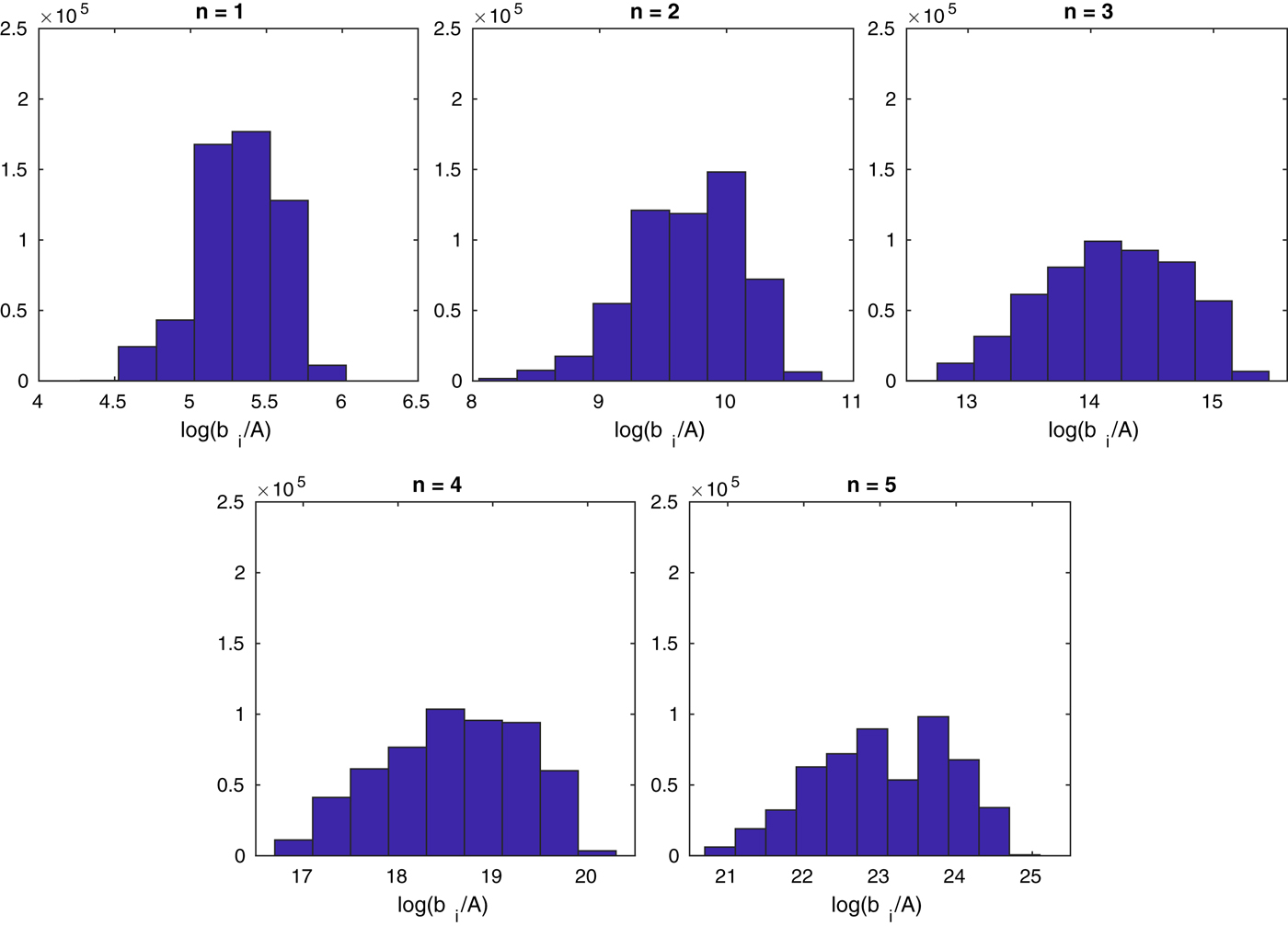
Using the average values of all the flowlines for $\dot {b_i}/A$ in Eqn (7), we found that the flowlines have an average thickness of between 266 and 308 m, depending on the value of n. This is 17–59 m thicker than the mean thickness found from the SHARAD estimated bedrock (249±50 m). The error is smallest for n = 1 and increases with increasing n-value (cf., Table 2). The reason for the overestimation of the thickness compared to the SHARAD estimation could be that more north-facing than south-facing flowlines have been used (45 north/north-west facing and 32 south/south-west facing), as generally, the thicknesses along flowlines on the south-facing LDAs are underestimated while those on the north-facing LDAs are overestimated (see Fig. 3). The possible reasons for this will be discussed in the next section. The results of the inversion are summarized in Table 2, and histograms of all the accepted values of the random walk can be seen in Figure 4. Since we did not invert for A directly, our results for the value of n apply to either choice of flow law (e.g. Eqn (4) orEqn (5)).
(a)–(d) Percentage deviation between the SHARAD derived LDA thickness and the thickness found using modelled flowlines for (a) n=1, (b) n=2, (c) n=3 and (d) n=4. (d) Results along flowline (shown with white line in Figures a–d) for different values of n.

Histograms of all accepted values of $\dot {b}_i/A$ for each value of n in the random walk.
The mean values of the ratio between the accumulation rate and the creep parameter $\dot {b}_i/A$ obtained from the inversion scheme, the root-mean square error (RMS) and the absolute percentage error (—εH—) of modelled ice thicknesses along flowlines compared to the radar estimated bedrock

Volumes (V ) are calculated using the interpolated modelled flowlines with the mean value of $\dot {b}_i/A$ for each value of n, and the percentage error (εV) of the total volume compared to the SHARAD volume (~ 449 km3) is given. The values calculated by using the whole area as well as by dividing the LDA into north and south facing parts are given.
Discussion
Error estimates
As shown in Table 2, the RMSE along the flowlines is in the range 87–113 m depending on the value of n. One of the reasons for the large errors is that there appears to be a difference in rheology between the north- and south-facing part of the LDA. The difference between the LDA thickness calculated using the mean value of $\dot b_i/A$ and the thickness simulated from SHARAD has different signs for the south-facing and north-facing part of the LDA. This suggests that the south-facing part of the LDA (i.e. poleward-facing), where the thickness is generally underestimated, needs a higher $\dot b_i/A$
 ratio than the north-facing (i.e. equator-facing) part, where the thickness is generally overestimated, in order to give the best fit. For example, the mean $\dot b_i/A$
 value for n = 3 for only south-facing flowlines is 9.2 × 10¹³ m Pa−3 (average slope = ~ 2°), whereas it is 3.8 × 10¹⁴ m Pa−3 for north-facing lines (average slope = ~ 3°). The ratio for the south-facing flow lines is therefore 75% times higher than for the northern-facing ones. Using different $\dot b_i/A$
 values for the north- and south-facing LDAs improves the uncertainties given in Table 2, especially for higher values of n. The absolute percentage error and the RMSE now lies between 27–31% and 80–86 m, respectively, depending on the value of n. The north-facing flowlines have an average RMSE of 53–61 m (23–26%) depending on n, while the south-facing flowlines have an average RMSE of 98–104 m (28–32%) (see Table 2).
Karlsson and others (Reference Karlsson, Schmidt and Hvidberg2015) and Parsons and Holt (Reference Parsons and Holt2016) also found that different parameterizations were needed for simulating the north- and south-facing parts of the LDA. Karlsson and others (Reference Karlsson, Schmidt and Hvidberg2015) found differences in the yield stress between the north- and south-facing LDAs in this area, while Parsons and Holt (Reference Parsons and Holt2016) found a difference in the rheological properties. Karlsson and others (Reference Karlsson, Schmidt and Hvidberg2015) suggested that a possible explanation for this is that the two sides experience different mass-balance regimes, as the north-facing side receives more solar insolation and thus the ice may be warmer and softer and/or experience more sublimation. However, Parsons and Holt (Reference Parsons and Holt2016) found that it is unlikely that only cause for the rheological differences is due to solar insolation, and instead suggested differences in ice grain size or timing of ice accumulation as potential explanations. Assuming that the formation of the VFFs was a global phenomena, or at least took place on a large regional scale, this indicates that local processes and conditions may have impacted the formation or subsequently altered the shape of the LDA after it formed.
Parsons and Holt (Reference Parsons and Holt2016) simulated the surface topography of the same LDA using a non-steady-state, time-marching simulation with n = 2 and achieved an RMSE of 23–30 m (for bedrock slopes of 0.5–1.5°) for the north-facing part, which is a significantly better fit than achieved in this study. The model used in this study relies on a steady-state assumption and a constant mass balance which only ablates by calving at the edges, and using a more complex numerical, non-steady-state model therefore captures the shape of the LDA more accurately. However, they achieved RMSE of 86–115 m (for bedrock slopes of 1–2°) for the south-facing part, which is closer to the values found in this study.
Both Parsons and Holt (Reference Parsons and Holt2016) and Karlsson and others (Reference Karlsson, Schmidt and Hvidberg2015) simulated a more accurate profile of the entire LDA than was possible with the steady-state method used in this study. The reason for this is most likely that the assumption of a steady-state accumulation is a cause of error, as it neglects the time- and space-varying mass-balance history of the deposit.
Implications for accumulation rate and temperature
From the results presented above, we now have an estimate of the ratio $\dot {b}_i/A$ for a range of different n-values. Here, we discuss how this ratio may be utilized to extract information on the accumulation rate and temperature assuming that our estimates from the inversion are correct. In the following, we use the mean $\dot {b}_i/A$
 for all flow lines to estimate the possible ranges of accumulation rate and temperature. In order to extract the absolute values of $\dot {b}_i$
 and A, we now have to make some assumptions on the value of A 0, and, depending on which flow law we select, the values of d and p. Depending on the value of n we either apply the values for A from Glen's flow law (n = 3) or from the reported values in Goldsby and Kohlstedt (Reference Goldsby and Kohlstedt2001). Table 1 gives an overview of the values we use and their reference.
The range of possible values for accumulation rate and temperature was found using the minimum and maximum allowed values of A and $\dot {b}_i$ , and then solving the equations $\dot {b}_{i,min}=A_{min}\cdot (\dot {b_i}/A)_{n}$
 and $\dot {b}_{i,max}=A_{max}\cdot (\dot {b_i}/A)_{n}$
 for each value of n. For example, for n=4 the minimum accumulation rate was calculated as:

This value is within the plausible accumulation range. We therefore further conclude that the value of A min in Eqn (8) is also possible. This value corresponds to a temperature of −83°C. The results for all values of n are summarized in Table 3.
The estimated minimum and maximum values of $\dot {b}_i$ and A for different values of n, found using the set minimum and maximum values for each parameter

A range in values is given for n≤2 to reflect the range in grain size (100 − 10−4 m).
The temperature range cannot be constrained for any of the values of n, as the calculated value of $\dot {b_i}/A$ in combination with the chosen constraints on the accumulation rate allows for the whole range of A-values (Table 1). The maximum accumulation rate needed to obtain the current shape assuming steady-state conditions is found to be in the order of 10−2 − 10−9 m a−1. In the likely scenario that the LDA was created during a previous climate with accumulation rates of the order of 1 mm a−1 or higher, our results indicate that the creep exponent should be n ≤3. However, it should be noted that the values of A and $\dot {b_i}$
 are very dependent on grain size for n ≤2. Larger grain size leads to lower values of A and the calculated value of $\dot {b_i}$
 lowers with the same factor. Thus, if we restrict the results to grain sizes of the order of 10−3 m (cf., Parsons and Holt, Reference Parsons and Holt2016), the values for the maximum accumulation rate are within the range of those estimated by Madeleine and others (Reference Madeleine2009).
Estimates of the velocities using Eqn (1) are given in Table 4. Unrealistically high velocities are found for n = 2 and a grain size of 10−4 m, but in general velocities of less than 1 mm a−1 are found. The velocity calculations therefore cannot help much in narrowing down the temperature range. When n = 2 and d = 10−4, the calculated velocities lead to a horizontal movement of ~2.4 km over 10 Myr for a temperature of T = 70°C. For all other cases, the horizontal movement is simulated to be between 0.05 and 190 m in 10 Myr for a temperature of T = 70°C.
The estimated minimum and maximum values of the velocity u and viscosity η for different values of n, found using the set minimum and maximum values from Table 3

A range in values is given for n ≤ 2 to reflect the range in grain size ($10^0\mbox {-}10^{-4}$ m).
m).
Flow properties
Goldsby and Kohlstedt (Reference Goldsby and Kohlstedt2001) provided evidence of four stress-dependent deformation mechanisms based on the laboratory experiments on fine-grained ice: (1) dislocation creep (at high stress regimes, n = 4), (2) superplastic flow (stresses below 100 kPa, n = 1.8), (3) basal slip (n = 2.4) and (4) diffusional flow (very low stresses, n = 1). The fact that n = 3 is suitable for a wide range of glaciers on Earth could be due to the combined effect of dislocation creep (n = 4) and superplastic deformation (n = 1.8) (Peltier and others, Reference Peltier, Goldsby, Kohlstedt and Tarasov2000).
For our study area, we hypothesize n ≤ 3, based on the increasing errors for higher values of n. Furthermore, Karlsson and others (Reference Karlsson, Schmidt and Hvidberg2015) estimated the yield stress of glaciers in this area to be only 37.7 kPa, which is consistent with the very low stresses associated with diffusive deformation found by Goldsby and Kohlstedt (Reference Goldsby and Kohlstedt2001). If n = 1, this would indicate that the LDA is dominated by diffusional flow. Interestingly, in their experiments Goldsby and Kohlstedt (Reference Goldsby and Kohlstedt2001) found no evidence for diffusional flow even for very small grain sizes of 3–5 × 10⁻⁶ m. However, since Goldsby and Kohlstedt (Reference Goldsby and Kohlstedt2001) used much higher stresses (minimum of ~2 MPa) than those experienced by Martian ice masses, diffusional flow on Mars could occur at larger grain sizes than 10−6 m. If n = 2, this indicates that the ice deformation is dominated by superplastic flow, probably in combination with other mechanisms. If n = 3, the deformation could be the combined effect of dislocation creep and superplastic deformation, similar to terrestrial glaciers. However, as the evolution of the crystal structure of ice that is several million years old is unknown, it is an open question how the ice crystals change over long time-scales to accommodate stress.
Qi and others (Reference Qi, Stern, Pathare, Durham and Goldsby2018) found that if ice masses consist of > 6% of non-ice material, grain boundary sliding is impeded and the ice deforms only due to dislocation creep. A value of n ≤ 3 is therefore consistent with an LDA consisting of > 94% ice.
Impact on volume calculations
We used the mean values of $\dot b_i/A$ for five values of n to estimate the ice volume in the area. The LDA has a total area of ~1970 km2, and an estimated ice volume of 435–504 km3 (Table 2), depending on the value of n. The LDA therefore has a mean thickness of 221–256 m. This is consistent with the results by Karlsson and others (Reference Karlsson, Schmidt and Hvidberg2015), who found a mean thickness of 232± 65 m in the same area, although that study included the average thickness of several LDAs in their final estimate. The fact that our inversion indicates that n = 1 gives a reasonable result indicates that the method of Karlsson and others (Reference Karlsson, Schmidt and Hvidberg2015) who estimated ice volumes using a simple plastic model is a good approximation. Estimating the volume using the bedrock estimated from SHARAD data leads to a total volume of 449± 90 km3 and a mean thickness of 228± 46 m. We note that the modelled volume results are therefore within the 25% uncertainty of the estimated volume from the SHARAD bedrock.
Applicability to other deformational features
Caution should be exercised when transferring our results to other VFFs or indeed other deformational features on Mars. For our results to be applicable, the composition of a feature should be predominantly water ice (H2O) since large quantities of impurities (> 10%) or the existence of other ices such as CO2 might modify the deformational properties (cf., Parsons and Holt, Reference Parsons and Holt2016). Assuming that majority of VFFs are composed of H2O-ice, we hypothesize that our results can be transferred to most LDAs and LVFs. This hypothesis is partly based on the wide range of model parameters permitted by the model results (see Table 3), which means that a large range of different temperatures and mass-balance regimes could be possible, and the results may describe a wide range of different LDAs. In addition, the hypothesis is based on the following observation: Using the dataset produced by Levy and others (Reference Levy, Fassett, Head, Schwartz and Watters2014), we plot all the CCFs, LDAs and LVFs mapped in the study on a logA, logV-scale (Fig. 5). From the figure it is evident that the log–log relationship between area and volume is linear for the LDAs and LVFs. This is a strong indication that they share deformational properties and that those properties are likely similar to terrestrial glaciers and ice sheets as noted in Karlsson and others (Reference Karlsson, Schmidt and Hvidberg2015). We therefore suggest that as long as the volume–area relationship for an LDA or LVF falls within the linear trend indicated in Figure 5, the deformational properties are likely to be similar to those of the LDA investigated here. However, it is important to note that this study still allows for large uncertainties in the ice rheology and accumulation rate, which means there are still large uncertainties in the deformational properties of these other LDAs.
The relationship between area and volume for VFFs mapped by Levy and others (Reference Levy, Fassett, Head, Schwartz and Watters2014). CCF, concentric crater fill; LVF, lineated valley fill; LDA, lobate debris apron. The relationship found by Karlsson and others (Reference Karlsson, Schmidt and Hvidberg2015) is included as a black line.

It is interesting that the CCFs clearly do not follow a linear trend, which could indicate a different formation history, different water–ice content and/or a different mass exchange with the atmosphere. For example, Weitz and others (Reference Weitz, Zanetti, Osinski and Fastook2018) suggest that CCFs started as lobate flow features which formed on crater walls, but with time the ice flowed into the crater floor. The shape of CCFs are therefore likely further from a steady state than LDAs.
In a broader perspective, our results indicate that care should be taken when transferring terrestrial deformation laws to extra-terrestrial water–ice. The viscous deformation of water–ice on, for example, Ceres, Europa, Enceladus, does not necessarily follow Glen's flow law (e.g. Miyamoto and others, Reference Miyamoto, Mitri, Showman and Dohm2005; Sori and others, Reference Sori2017).
Conclusion
We investigate an LDA surrounding a massif in the southern hemisphere of Mars using SHARAD radargrams, a high-resolution DEM and a non-linear 1D ice-flow model. We assume that the shape of the LDA is a steady-state shape and that it has not been modified since its formation. We apply an inverse Monte Carlo method in order to infer the unknown parameters in the model: the creep exponent n, the flow parameter A and the specific accumulation rate $\dot {b_i}$ . In order to arrive at stable distributions, we invert for the ratio $\dot {b_i}/A$
 for four different values of the creep exponent; n = 1, 2, 3, 4 and 5. Generally, the misfit between observations and model results increase with increasing values of n, with lowest absolute error for n = 1 (30%) and the highest absolute error for n=5 (37%).
We further determine an interval of possible values of $\dot {b_i}$ and A for values of n = 1, 2, 3 and 4, using the mean value of the $\dot {b_i}/A$
 ratio. For the solutions where n ≤2, the possible values depend on the grain size, and thus a large span in $\dot {b_i}$
 and A values is possible. In addition, a wide range of temperatures return a reasonable fit to the shapes. Therefore, while we cannot constrain the temperature, we infer that the values of n ≤ 2 with a large grain size are most likely if the LDA shape was formed by a climate where little mass is exchanged between the atmosphere and the deposits, while if the grain size of the deposit is small (~ 10−4 m), a warmer climate with an accumulation rate in the order of 10−3–10−2 m a−1 is more likely. However, for n=2 and a grain size ~10−4 m, unrealistically high surface velocities are found. In the case of n = 3, a wide range of temperatures and accumulation rates can fit the shape of the flow lines. Thus, in this case we cannot exclude neither a cold, dry climate nor a warmer climate with the accumulation rates of the order of 10−3 m a−1. We find similar results for n = 4, albeit with a maximum accumulation rates in the order of 10−4 m a−1. However, since we obtain a better fit between observations and model results for n ≤ 3 than for results for n ≥ 4 we favour the scenarios where the likely value of n is n ≤ 3. This also agrees with the studies suggesting that the LDA is most likely experiencing low stresses (Karlsson and others, Reference Karlsson, Schmidt and Hvidberg2015).
Using the mean values of the probability distributions, the ice depth along flowlines and the ice volume of the LDA is estimated. We find a total ice volume of 435–504 km3 and a mean thickness of 221–256 m. This is consistent with the volume found using SHARAD data, which is 449±90 km3. Finally, we conclude that a simple plastic model is a reasonable approximation to estimate ice volumes of LDAs.
Acknowledgments
LSS is supported by the University of Iceland Eimskip Fund. The Centre for Ice and Climate is funded by the Danish National Research Foundation. We gratefully acknowledge Isaac Smith, Michael Sori and an anonymous reviewer whose insightful comments and suggestions improved the quality of this manuscript. The data and results from this study can be obtained by contacting the corresponding author. HRSC products are freely accessible via Planetary Science Archive (PSA) of European Space Agency or Planetary Data System (PDS) of NASA.


 Open access

