

Preface
The Dawes Reviews are substantial reviews of topical areas in astronomy, published by authors of international standing at the invitation of the PASA Editorial Board. The reviews recognise William Dawes (1762–1836), second lieutenant in the Royal Marines and the astronomer on the First Fleet. Dawes was not only an accomplished astronomer, but spoke five languages, had a keen interest in botany, mineralogy, engineering, cartography, and music, compiled the first Aboriginal-English dictionary, and was an outspoken opponent of slavery.
1 INTRODUCTION
A planet is a celestial body moving in an elliptic orbit around a star. Although there does not appear to be a sharp boundary in terms of properties, objects more massive than ≈ 13MJ are called brown dwarfs (BDs) since they can fuse deuterium while planets are never sufficiently hot for that (Burrows et al. Reference Burrows, Hubbard, Lunine and Liebert2001).
Formation of a star begins when a large cloud dominated by molecular hydrogen collapses due to its self-gravity. The first hydrostatic object that forms in the centre of the collapsing cloud is a gaseous sphere of 1 to a few Jupiter masses; it grows rapidly by accretion of more gas from the cloud (Larson Reference Larson1969). Due to an excess angular momentum, material accreting onto the protostar forms a disc of gas and dust. Planets form out of this (protoplanetary) disc, explaining the flat architecture of both the Solar System (SS) and the extra-solar planetary systems (Fabrycky et al. Reference Fabrycky2014; Winn & Fabrycky Reference Winn and Fabrycky2015).
The most widely accepted theory of planet formation is the Core Accretion (CA) scenario, pioneered by Safronov (Reference Safronov1972). In this scenario, microscopic grains in the protoplanetary disc combine to yield asteroid-sized bodies (e.g., Goldreich & Ward Reference Goldreich and Ward1973), which then coalesce to form rocky and/or icy planetary cores (Wetherill Reference Wetherill1990; Kenyon & Luu Reference Kenyon and Luu1999). These solid cores accrete gas from the disc when they become sufficiently massive (Mizuno Reference Mizuno1980; Stevenson Reference Stevenson1982; Ikoma, Nakazawa, & Emori Reference Ikoma, Nakazawa and Emori2000; Rafikov Reference Rafikov2006), becoming gas giant planets (Pollack et al. Reference Pollack1996; Alibert et al. Reference Alibert, Mordasini, Benz and Winisdoerffer2005; Mordasini et al. Reference Mordasini, Mollière, Dittkrist, Jin and Alibert2015).
Kuiper (Reference Kuiper1951) envisaged that a planet’s life begins as that of stars, by gravitational instability, with formation of a few Jupiter mass gas clump in a massive protoplanetary disc. In difference to stars, young planets do not accrete more gas in this picture. They may actually lose most of their primordial gas if tidal forces from the host stars are stronger than self-gravity of the clumps. However, before the clumps are destroyed, solid planetary cores are formed inside them when grains grow and sediment to the centre (McCrea & Williams Reference McCrea and Williams1965). In this scenario, the inner four planets in the SS are the remnant cores of such massive gas condesations. Jupiter, on the other hand, is an example of a gas clump that was not destroyed by the stellar tides because it was sufficiently far from the Sun. The other three giants in the SS are partially disrupted due to a strong negative feedback from their massive cores (Handbury & Williams Reference Handbury and Williams1975, and Section 3.3).
It was later realised that gas clumps dense and yet cool enough for dust grain growth and sedimentation could not actually exist at the location of the Earth for more than a year, so Kuiper’s suggestion lost popularity (Donnison & Williams Reference Donnison and Williams1975). However, recent simulations show that gas fragments migrate inward rapidly from their birth place at ~ 100 AU, potentially all the way into the star (Boley et al. Reference Boley, Hayfield, Mayer and Durisen2010, more references in Section 4.2). Simulations also show that grain sedimentation and core formation can occur inside the clumps while they are at separations of tens of AU, where the stellar tides are weaker. The clumps may eventually migrate to a few AU and could then be tidally disrupted. Kuiper’s top-down scenario of planet formation is therefore made plausible by planet migration; it was recently re-invented (Boley et al. Reference Boley, Hayfield, Mayer and Durisen2010) and re-branded ‘Tidal Downsizing’ hypothesis (Nayakshin Reference Nayakshin2010a).
This review presents the main ideas behind the Tidal Downsizing scenario, recent theoretical progress, detailed numerical simulations and a wide comparison to the current observational data. An attempt is made at finding a physically self-consistent set of assumptions within which Tidal Downsizing hypothesis could account for all observational facts relevant to the process of planet formation.
Exploration of this extreme scenario is the quickest route to rejecting the Tidal Downsizing hypothesis or constraining its inner workings if it is successful. Further, it is possible that the final planet formation theory will combine elements of both Tidal Downsizing and CA, e.g., by having them operating at different epochs, scales, or systems. By pushing the Tidal Downsizing scenario to the limit, we may locate the potential phase space divide between the two theories sooner.
This review is structured as following. Section 3 lists important physical processes underpinning the scenario and points out how they could combine to account for the SS’s structure. Sections 4–7 present detailed calculations that constrain these processes, whereas Section 8 overviews a population synthesis approach for making statistical model predictions. Section 9–14 are devoted to the comparison of Tidal Downsizing’s predictions with those of CA and the current observations. Section 15 is a brief summary of the same for the SS. The Discussion (Section 16) presents a summary of how Tidal Downsizing might relate to the exoplanetary data, observations that could distinguish between the Tidal Downsizing and the CA scenarios, open questions, and potential weaknesses of Tidal Downsizing.
2 OBSERVATIONAL CHARACTERISTICS OF PLANETARY SYSTEMS
In terms of numbers, ~ 90% of planets are those less massive than ~ 20M ⊕ (Mayor et al. Reference Mayor2011; Howard et al. Reference Howard2012). These smaller planets tend to be dominated by massive solid cores with gas envelopes accounting for a small fraction of their mass budget only, from tiny (like on Earth) to ~ 10%. There is a very sharp rollover in the planet mass function (PMF) above the mass of ~ 20M ⊕. On the other end of the mass scale, there are gas giant planets that are usually more massive than ~ 100M ⊕ and consist mainly of a H/He gas mixture enveloping a solid core. In terms of environment, planets should be able to form as close as ≲ 0.05 AU from the host star (Mayor & Queloz Reference Mayor and Queloz1995) to as far away as tens and perhaps even hundreds of AU (Marois et al. Reference Marois2008; Brogan et al. Reference Brogan2015).
Both small and large planets are not just smaller pieces of their host stars: Their bulk compositions are over-abundant in metals compared to their host stars (Guillot Reference Guillot2005; Miller & Fortney Reference Miller and Fortney2011). Planet formation process should also provide a route to forming smaller ~ 1–1000 km sized solid bodies, called planetesimals, such as those in the asteroid and the Kuiper belt in the SS and the debris discs around nearby stars (Wyatt Reference Wyatt2008).
While gas giant planet detection frequency is a strongly increasing function of the host star’s metallicity (Fischer & Valenti Reference Fischer and Valenti2005), the yield of observed smaller members of the planetary system—massive solid cores (Buchhave et al. Reference Buchhave2012; Wang & Fischer Reference Wang and Fischer2015) and debris discs (Moro-Martín et al. Reference Moro-Martín2015)—do not correlate with metallicity.
One of the observational surprises of the last decade has been the robustness of the planet formation process. Planets must form in under 3 (Haisch, Lada, & Lada Reference Haisch, Lada and Lada2001) and perhaps even 1 Myr (Brogan et al. Reference Brogan2015, and Section 13), and also in very dynamic environments around eccentric stellar binaries (e.g., Welsh et al. Reference Welsh2012) and also orbiting the primary in eccentric binary systems such as Kepler-444 (Dupuy et al. Reference Dupuy2016, Section 14).
It was argued in the past that formation pathways of BDs and of more massive stellar companions to stars should be distinct from those of planets (e.g., Winn & Fabrycky Reference Winn and Fabrycky2015) because of their different metallicity correlations and other properties. However, observations now show a continuous transition from gas giant planets to BDs on small orbits in terms of their metal content, host star metallicity correlations, and the frequency of appearance (see Section 9.5.1). Also, observations show that planets and stellar companions are often members of same systems. There are stellar multiple systems whose orbital structure is very much like that of planetary systems (e.g., Tokovinin et al. Reference Tokovinin, Latham and Mason2015). This suggests that we need a theory that can address formation of both planetary and stellar mass companions in one framework (as believed by Kuiper Reference Kuiper1951).
3 TIDAL DOWNSIZING HYPOTHESIS
3.1. Basic steps
Tidal Downsizing hypothesis is a sequence of four steps, illustrated in Figure 1:
-
(1) A gas clump of Jovian mass is born at separation of ~ 100 AU from the star in a gravitationally unstable gas disc (see Section 4.1).
-
(2) The clump migrates inward rapidly due to torques from the disc, as shown by simulations (Section 4.2).
-
(3) A core and solid debris (planetesimals) form in the centre of the clump by grain sedimentation and gravitational instability of the solid component in the centre of the clump (Sections 5.2, 5.3, 7).
-
(4A) If the fragment did not contract sufficiently from its initial extended state, it is disrupted by tides from the star (Boley et al. Reference Boley, Hayfield, Mayer and Durisen2010, and Section 6.1). The core and the debris are released back into the disc, forming debris rings (shown as a brown oval filled with a patern in Figure 1). The core continues to migrate in, although at a slower rate.
-
(4B) If the fragment contracts faster than it migrates, then it is not disrupted and becomes a gas giant planet with a core. Note that the latter does not have to be massive.
Tidal Downsizing hypothesis is a sequence of four steps: (1) gas clump birth; (2) migration; (3) grain sedimentation and core formation; (4) disruption. Not all of these steps may occur for a given clump (see Section 3.1 for detail).

The planet formation process ends when the gas disc is dissipated away (Alexander et al. Reference Alexander, Pascucci, Andrews, Armitage, Cieza, Beuther, Klessen, Dullemond and Henning2014).
3.2. Key concepts and physical constraints
Pre-collapse gas fragments, formed by gravitational instability in the disc (see Sections 6 and 6.1) are initially cool, with central temperatures T c ~ a hundred K, and extended, with the radius of the clump (planet) estimated as (Nayakshin Reference Nayakshin2015a)
 $$\begin{equation}
R_{\rm p} \approx 0.7 {G M_{\rm p}\mu \over k_{\text{b}} T_{\rm c}} \approx 2 \hbox{AU} \left({M_{\rm p}\over 1 {\,{\rm M}_{\rm J}}}\right) T_2^{-1}\;,
\end{equation}$$
$$\begin{equation}
R_{\rm p} \approx 0.7 {G M_{\rm p}\mu \over k_{\text{b}} T_{\rm c}} \approx 2 \hbox{AU} \left({M_{\rm p}\over 1 {\,{\rm M}_{\rm J}}}\right) T_2^{-1}\;,
\end{equation}$$
where T
2 = T
c/100 K, and $\mu \approx 2.43 m_{\text{p}}$
is the mean molecular weight for Solar composition molecular gas. Clump effective temperatures are typically of order of tens of K (e.g., Vazan & Helled Reference Vazan and Helled2012). The fragments are expected to contract rapidly and heat up initially; when reaching T
c ~ 1000 K their contraction becomes much slower (e.g., Figure 1 in Nayakshin Reference Nayakshin2015a).
$\mu \approx 2.43 m_{\text{p}}$
is the mean molecular weight for Solar composition molecular gas. Clump effective temperatures are typically of order of tens of K (e.g., Vazan & Helled Reference Vazan and Helled2012). The fragments are expected to contract rapidly and heat up initially; when reaching T
c ~ 1000 K their contraction becomes much slower (e.g., Figure 1 in Nayakshin Reference Nayakshin2015a).
Second collapse. If the planet contracts to the central temperature T c ~ 2000 K, it collapses rapidly due to H2 dissociation (Bodenheimer Reference Bodenheimer1974) into the ‘second core’ (Larson Reference Larson1969), which has T c ≳ 20000 K and a radius of only R p ~ 1R⊙ ≈ 0.005 AU (see Section 6.1).
Super-migration. Numerical simulations (Section 4.2) show that gas clumps born by gravitational instability ‘super-migrate’ in, that is, their separation from the star may shrink from a ~ 100 AU to arbitrarily close to the star, unless the disc dissipates earlier. The migration time t mig is from a few thousand years to a few × 105 yrs at late times when the disc mass is low.
Tidal disruption of the planet takes place if its radius is larger than the Hill radius of the planet,
 $$\begin{equation}
R_{\rm H} = a \left({M_{\rm p}\over 3 M_*}\right)^{1/3} \approx 0.07 a \left({M_{\rm p}\over 1 {\,{\rm M}_{\rm J}}}\right)^{1/3}\;,
\end{equation}$$
$$\begin{equation}
R_{\rm H} = a \left({M_{\rm p}\over 3 M_*}\right)^{1/3} \approx 0.07 a \left({M_{\rm p}\over 1 {\,{\rm M}_{\rm J}}}\right)^{1/3}\;,
\end{equation}$$
where a is the planet–star separation and M * was set to 1M⊙. Pre-collapse fragments can be disrupted at a ~ a few to tens of AU whereas post-collapse planets are safe from tidal disruptions except perhaps for very small separations, a ≲ 0.1 AU.
Exclusion zone. The smallest separation which a migrating pre-collapse gas fragment can reach is found by comparing equations (2) and (1) for T c = 2000 K:
 $$\begin{equation}
a_{\rm exc} = 1.33 \hbox{ AU } \left({ M_{\rm p}\over 1 {\,{\rm M}_{\rm J}}}\right)^{2/3}\;.
\end{equation}$$
$$\begin{equation}
a_{\rm exc} = 1.33 \hbox{ AU } \left({ M_{\rm p}\over 1 {\,{\rm M}_{\rm J}}}\right)^{2/3}\;.
\end{equation}$$
This implies that there should be a drop in the number of gas giant planets inwards of a exc. Inside the exclusion zone, only the planets that managed to collapse before they were pushed to a exc remain gas giants.
Grain sedimentation is possible inside pre-collapse fragments (see Section 7, McCrea & Williams Reference McCrea and Williams1965) as long as the fragments are cooler than ~ 1500 K. Grain growth and sedimentation time scales are a few thousand years (equation 17). Massive core (M core ⩾ 1M ⊕) assembly may however require from 104 to a few × 105 yrs.
Planetesimals are debris of disrupted planets in the model, and are born only when and where these disruptions take place (Section 5.3 and 7.3). The relation between planets and planetesimals are thus inverse to what it is in the CA picture.
Pebble accretion. 0.1 cm or larger grains accreting onto the planet may accelerate its collapse by increasing the planet weight (Section 6.3). This process leads to distinct testable metallicity correlation signatures.
Negative feedback by cores more massive than a few M ⊕. These cores release so much heat that their host gas clumps expand and may lose their gas completely, somewhat analogously to how red giant stars lose their envelopes. Core feedback can destroy gas clumps at separations as large as tens of AU (Section 7.5).
3.3. A zeroth-order Solar System model
Figure 2 shows a schematic Tidal Downsizing model for the formation of the SS. In this picture, the inner four terrestrial planets are the remnants of gas fragments that migrated in most rapidly and lost their gaseous envelopes due to the tides from the Sun at separations a ≳ a exc, e.g., a few AU (cf. equation 3), potentially explaining the origin and the location of the Asteroid belt. Since these fragments were made earlier when the disc was likely more massive, they migrated in very rapidly and had little time for core assembly. This may explain qualitatively why the terrestrial planet masses are so low compared to the much more massive cores of the four giants.
A qualitative model for the Solar System formation in Tidal Downsizing, described in Section 3.3. In this scenario, the Solar System was formed by tidal disruption of the first four gas fragments (Mercury to Mars), survival of the fifth (Jupiter), and disruption of the outer three fragments due to feedback from their very bright cores (Saturn, Uranus, and Neptune).

Continuing this logic, we should expect that the mass of a core in the planet increases with the distance from the Sun, in general. If the Jupiter’s core mass is below ≲ 5M ⊕, that is in between the terrestrial planet mass and the more distant ‘ice giants’ (such a core mass is allowed by the Jupiter’s interior models, e.g., Guillot Reference Guillot2005), then Jupiter was not strongly affected by the feedback from its core. It is therefore reasonable that Jupiter kept all or a major fraction of its primordial H/He content at its current location of 5.2 AU. Pebble accretion onto Jupiter, and/or partial H/He mass loss, made its bulk composition metal rich compared with the Sun.
Even further from the Sun, Saturn, Uranus, and Neptune are expected to have even larger cores, which is consistent with Saturn’s core (constrained to weigh $5\text{--}20{\,{\rm M}_{\rm J}}$
, see Helled & Guillot Reference Helled and Guillot2013) most likely being heavier than Jupiter’s, and with Uranus and Neptune consisting mainly of their cores, so having M
core ≳ 10M
⊕. At these high core masses, the three outer giants of the SS evolved differently from Jupiter. In this model, they would have had their envelopes puffed up to much larger sizes than Jupiter had. Saturn has then lost much more of its primordial H/He than Jupiter, with some of the gas envelope still remaining bound to its massive core. Uranus and Neptune envelopes’ were almost completely lost. As with the Asteroid belt, the Kuiper belt is the record of the tidal disruptions that made Saturn, Uranus, and Neptune. A more detailed interpretation of the SS in the Tidal Downsizing scenario is given in Section 15.
$5\text{--}20{\,{\rm M}_{\rm J}}$
, see Helled & Guillot Reference Helled and Guillot2013) most likely being heavier than Jupiter’s, and with Uranus and Neptune consisting mainly of their cores, so having M
core ≳ 10M
⊕. At these high core masses, the three outer giants of the SS evolved differently from Jupiter. In this model, they would have had their envelopes puffed up to much larger sizes than Jupiter had. Saturn has then lost much more of its primordial H/He than Jupiter, with some of the gas envelope still remaining bound to its massive core. Uranus and Neptune envelopes’ were almost completely lost. As with the Asteroid belt, the Kuiper belt is the record of the tidal disruptions that made Saturn, Uranus, and Neptune. A more detailed interpretation of the SS in the Tidal Downsizing scenario is given in Section 15.
The SS is not very special in this scenario, being just one of thousands of possible realisations of Tidal Downsizing (see Figure 25). The main difference between the SS and a typical observed exoplanetary system (e.g., Winn & Fabrycky Reference Winn and Fabrycky2015) may be that the proto-Solar Nebula was removed relatively early on, before the planets managed to migrate much closer in to the Sun. The spectrum of Tidal Downsizing realisations depends on many variables, such as the disc metallicity, the timing of the gas disc removal, the number and the masses of the gas clumps and the planetary remnants, and the presence of more massive stellar companions. There is also a very strong stochastic component due to the clump–clump and the clump–spiral arm interactions (Cha & Nayakshin Reference Cha and Nayakshin2011).
4 MULTIDIMENSIONAL GAS DISC SIMULATIONS
4.1. Disc fragmentation
To produce Jupiter at its current separation of a ≈ 5 AU via disc fragmentation (Kuiper Reference Kuiper1951), the protoplanetary disc needs to be very massive and unrealistically hot (e.g., Goldreich & Ward Reference Goldreich and Ward1973; Cassen et al. Reference Cassen, Smith, Miller and Reynolds1981; Laughlin & Bodenheimer Reference Laughlin and Bodenheimer1994). Analytical arguments and 2D simulations with a locally fixed cooling time by Gammie (Reference Gammie2001) showed that self-gravitating discs fragment only when (1) the Toomre (Reference Toomre1964) Q-parameter is smaller than ~ 1.5, and (2) when the disc cooling time is t
cool = βΩ−1
K
≲ a few times the local dynamical time, which is defined as $1/\Omega _{\text{K}} = (R^3/GM_*)^{1/2}$
, where M
* is the protostar’s mass. The current consensus in the community is that formation of planets any closer than tens of AU via gravitational instability of its protoplanetary disc in situ is very unlikely (e.g., see Rafikov Reference Rafikov2005; Rice et al. Reference Rice, Lodato and Armitage2005; Durisen et al. Reference Durisen, Reipurth, Jewitt and Keil2007; Rogers & Wadsley Reference Rogers and Wadsley2012; Helled et al. Reference Helled, Beuther, Klessen, Dullemond and Henning2014; Young & Clarke Reference Young and Clarke2016), although some authors find their discs to be fragmenting for β as large as 30 in their simulations (Meru & Bate Reference Meru and Bate2011, Reference Meru and Bate2012; Paardekooper Reference Paardekooper2012).
$1/\Omega _{\text{K}} = (R^3/GM_*)^{1/2}$
, where M
* is the protostar’s mass. The current consensus in the community is that formation of planets any closer than tens of AU via gravitational instability of its protoplanetary disc in situ is very unlikely (e.g., see Rafikov Reference Rafikov2005; Rice et al. Reference Rice, Lodato and Armitage2005; Durisen et al. Reference Durisen, Reipurth, Jewitt and Keil2007; Rogers & Wadsley Reference Rogers and Wadsley2012; Helled et al. Reference Helled, Beuther, Klessen, Dullemond and Henning2014; Young & Clarke Reference Young and Clarke2016), although some authors find their discs to be fragmenting for β as large as 30 in their simulations (Meru & Bate Reference Meru and Bate2011, Reference Meru and Bate2012; Paardekooper Reference Paardekooper2012).
The Toomre (Reference Toomre1964) Q-parameter must satisfy
 $$\begin{equation}
Q = {c_{\text{s}} \Omega \over \pi G\Sigma } \approx {H\over R} { M_* \over M_{\rm d}}\lesssim 1.5\;,
\end{equation}$$
$$\begin{equation}
Q = {c_{\text{s}} \Omega \over \pi G\Sigma } \approx {H\over R} { M_* \over M_{\rm d}}\lesssim 1.5\;,
\end{equation}$$
where $c_{\text{s}}$
and Σ are the disc sound speed and surface density, respectively. The second equality in equation (4) assumes hydrostatic balance, in which case
$c_{\text{s}}$
and Σ are the disc sound speed and surface density, respectively. The second equality in equation (4) assumes hydrostatic balance, in which case $c_{\text{s}}/H = \Omega$
(Shakura & Sunyaev Reference Shakura and Sunyaev1973), where H is the disc vertical height scale. The disc mass at radius R was defined as M
d(R) = ΣπR
2. Finally, Ω2 ≈ GM
*/R
3, neglecting the mass of the disc compared to that of the star, M
*. Since H/R∝T
1/2
d, where T
d is the disc mid plane temperature, we see that to fragment, the disc needs to be (a) relatively cold and (b) massive. In particular, assuming H/R ~ 0.2 (Tsukamoto et al. Reference Tsukamoto, Takahashi, Machida and Inutsuka2015) at R ~ 50 − 100 AU, the disc mass at fragmentation is estimated as
$c_{\text{s}}/H = \Omega$
(Shakura & Sunyaev Reference Shakura and Sunyaev1973), where H is the disc vertical height scale. The disc mass at radius R was defined as M
d(R) = ΣπR
2. Finally, Ω2 ≈ GM
*/R
3, neglecting the mass of the disc compared to that of the star, M
*. Since H/R∝T
1/2
d, where T
d is the disc mid plane temperature, we see that to fragment, the disc needs to be (a) relatively cold and (b) massive. In particular, assuming H/R ~ 0.2 (Tsukamoto et al. Reference Tsukamoto, Takahashi, Machida and Inutsuka2015) at R ~ 50 − 100 AU, the disc mass at fragmentation is estimated as
 $$\begin{equation}
{M_{\rm d}\over M_*} \approx 0.15 \left( {1.5\over Q} \right) \left({H \over 0.2 \; R}\right) \;.
\end{equation}$$
$$\begin{equation}
{M_{\rm d}\over M_*} \approx 0.15 \left( {1.5\over Q} \right) \left({H \over 0.2 \; R}\right) \;.
\end{equation}$$
Lin & Pringle (Reference Lin and Pringle1987) argued that effective αsg generated by spiral density waves should saturate at around unity when the Toomre’s parameter Q approaches unity from above. Simulations (Gammie Reference Gammie2001; Lodato & Rice Reference Lodato and Rice2004, Reference Lodato and Rice2005) show that αsg for non-fragmenting discs does not exceed ~ 0.1. This constrains the disc viscous time scale as
 $$\begin{equation}
t_{\rm visc} = {1\over \alpha } {R^2 \over H^2} {1\over \Omega _K} \approx 4\times 10^4 \; \rm yrs \; \alpha _{0.1}^{-1} R_2^{3/2}\;,
\end{equation}$$
$$\begin{equation}
t_{\rm visc} = {1\over \alpha } {R^2 \over H^2} {1\over \Omega _K} \approx 4\times 10^4 \; \rm yrs \; \alpha _{0.1}^{-1} R_2^{3/2}\;,
\end{equation}$$
where α0.1 = α/0.1, R 2 = R/100 AU, and H/R was set to 0.2. Thus, gravitationally unstable discs may evolve very rapidly, much faster than the disc dispersal time ( ~ 3 million yrs; Haisch et al. Reference Haisch, Lada and Lada2001). However, once the disc loses most of its mass via accretion onto the star, αsg may drop well below ~ 0.1 and the disc then may persist for much longer in a non-self-gravitating state.
4.2. Rapid fragment migration
Kuiper (Reference Kuiper1951) postulated that SS planets did not migrate. The importance of planet migration for CA theory was realised when the first hot Jupiter was discovered (Mayor & Queloz Reference Mayor and Queloz1995; Lin et al. Reference Lin, Bodenheimer and Richardson1996), but gravitational instability planets remained ‘immune’ to this physics for much longer.
Vorobyov & Basu (Reference Vorobyov and Basu2005, Reference Vorobyov and Basu2006) performed numerical simulations of molecular cloud core collapse and protostar growth. As expected from the previous fixed cooling time studies (Section 4.1), their discs fragmented only beyond ~ 100 AU. However, their fragments migrated inward towards the protostar very rapidly, on time scales of a few to ten orbits ( ~ O(104) yrs). The clumps were ‘accreted’ by their inner boundary condition at 10 AU. This could be relevant to the very well-known ‘luminosity problem’ of young protostars (Hartmann et al. Reference Hartmann, Calvet, Gullbring and D’Alessio1998): observed accretion rates of protostars are too small to actually make ~ 1 Solar mass stars within the typical disc lifetime. The missing mass is believed to be accreted onto the stars during the episodes of very high accretion rate bursts, $\dot{M} \gtrsim 10^{-4}{\,{\rm M}_{\odot }}$
yr−1, which are rare. The high accretion rate protostars are called ‘FU Ori’ sources (e.g., Hartmann & Kenyon Reference Hartmann and Kenyon1996); statistical arguments suggest that a typical protostar goes through a dozen of such episodes. Although other possibilities exist (Bell & Lin Reference Bell and Lin1994; Armitage, Livio, & Pringle Reference Armitage, Livio and Pringle2001), massive migrating clumps driven into the inner disc and being rapidly disrupted there yield a very natural mechanism to solve the luminosity problem (Dunham & Vorobyov Reference Dunham and Vorobyov2012) and the origin of the FU Ori sources (Nayakshin & Lodato Reference Nayakshin and Lodato2012). Future observations of FU Ori outburst sources may give the presence of close-in planets away by quasi-periodic variability in the accretion flow (e.g., Powell et al. Reference Powell, Irwin, Bouvier and Clarke2012). Recent coronagraphic Subaru 8.2-m telescope imaging in polarised infrared light of several brightest young stellar objects (YSO), including FU Ori, have shown evidence for large-scale spiral arms on scales larger than 100 AU in all of their sources (Liu et al. Reference Liu2016). The authors suggest that such spiral arms may indeed be widespread amongst FU Ori sources. This would support association of FU Ori with migrating gas clumps.
$\dot{M} \gtrsim 10^{-4}{\,{\rm M}_{\odot }}$
yr−1, which are rare. The high accretion rate protostars are called ‘FU Ori’ sources (e.g., Hartmann & Kenyon Reference Hartmann and Kenyon1996); statistical arguments suggest that a typical protostar goes through a dozen of such episodes. Although other possibilities exist (Bell & Lin Reference Bell and Lin1994; Armitage, Livio, & Pringle Reference Armitage, Livio and Pringle2001), massive migrating clumps driven into the inner disc and being rapidly disrupted there yield a very natural mechanism to solve the luminosity problem (Dunham & Vorobyov Reference Dunham and Vorobyov2012) and the origin of the FU Ori sources (Nayakshin & Lodato Reference Nayakshin and Lodato2012). Future observations of FU Ori outburst sources may give the presence of close-in planets away by quasi-periodic variability in the accretion flow (e.g., Powell et al. Reference Powell, Irwin, Bouvier and Clarke2012). Recent coronagraphic Subaru 8.2-m telescope imaging in polarised infrared light of several brightest young stellar objects (YSO), including FU Ori, have shown evidence for large-scale spiral arms on scales larger than 100 AU in all of their sources (Liu et al. Reference Liu2016). The authors suggest that such spiral arms may indeed be widespread amongst FU Ori sources. This would support association of FU Ori with migrating gas clumps.
In the planet formation literature, gas fragment migration was rediscovered by Boley et al. (Reference Boley, Hayfield, Mayer and Durisen2010), who modelled massive and large protoplanetary discs (although the earliest mention of gas fragment migration may have been made by Mayer et al. Reference Mayer, Quinn, Wadsley and Stadel2004). They found that gravitational instability fragments are usually tidally disrupted in the inner disc. Similar rapid migration of fragments was seen by Inutsuka et al. (Reference Inutsuka, Machida and Matsumoto2010), Machida et al. (Reference Machida, Inutsuka and Matsumoto2011), Cha & Nayakshin (Reference Cha and Nayakshin2011), Zhu et al. (Reference Zhu, Hartmann, Nelson and Gammie2012). Baruteau, Meru, & Paardekooper (Reference Baruteau, Meru and Paardekooper2011) (see Figure 3) and Michael et al. (Reference Michael, Durisen and Boley2011) found that gas giants they migrate inward so rapidly because they do not open gaps in self-gravitating discs. This is known as type I migration regime (see the review by Baruteau et al. Reference Baruteau, Beuther, Klessen, Dullemond and Henning2014). For a laminar disc, the type I migration time scale, defined as $\text{d}a/\text{d}t = - a/t_{\rm I}$
where a is the planet separation from the star,
$\text{d}a/\text{d}t = - a/t_{\rm I}$
where a is the planet separation from the star,
 $$\begin{equation}
t_{\rm I} = (\Gamma \Omega )^{-1} Q \frac{M_*}{M_{\rm p}}\frac{H}{a} = 3\times 10^4 \;\hbox{yrs}\; a_2^{3/2} \frac{H}{0.2 a} {Q\over \Gamma } q_{-3}^{-1},
\end{equation}$$
$$\begin{equation}
t_{\rm I} = (\Gamma \Omega )^{-1} Q \frac{M_*}{M_{\rm p}}\frac{H}{a} = 3\times 10^4 \;\hbox{yrs}\; a_2^{3/2} \frac{H}{0.2 a} {Q\over \Gamma } q_{-3}^{-1},
\end{equation}$$
where q −3 = 1000M p/M * is the planet to star mass ratio scaled to 0.001, a 2 = a/100 AU, and Γ is a dimensionless factor that depends on the disc surface density profile and thermodynamical properties (Γ is the modulus of equation (6) in Baruteau et al. Reference Baruteau, Meru and Paardekooper2011). Simulations show that Γ ~ a few to ten for self-gravitating discs, typically.
Numerical simulations of a Jupiter mass planet migrating in a self-gravitating protoplanetary disc (Baruteau et al. Reference Baruteau, Meru and Paardekooper2011). The planets are inserted in the disc at separation of 100 AU, and migrate inward in a few thousand years. Different curves are for the same initial disc model but for the planet starting at eight different azimuthal locations. The inset shows the disc surface density map.

Due to the chaotic nature of gravitational torques that the planet receives from the self-gravitating disc, planet migration is not a smooth monotonic process. This can be seen from the migration tracks in Figure 3, which are for the same disc with cooling parameter β = 15 and the same M p = 1MJ planet, all placed at a = 100 AU initially, but with varying azimuthal angles ϕ in the disc. The extremely rapid inward migration slows down only when deep gaps are opened in the disc, which typically occur when q > 0.01 − 0.03 at tens of au distances. This is appropriate for BD mass companions.
4.3. Fragment mass evolution
Most authors find analytically that initial fragment mass, M in, at the very minimum is 3MJ (e.g., Rafikov Reference Rafikov2005; Kratter, Murray-Clay, & Youdin Reference Kratter, Murray-Clay and Youdin2010; Forgan & Rice Reference Forgan and Rice2011, Reference Forgan and Rice2013a; Tsukamoto, Takahashi, Machida, & Inutsuka Reference Tsukamoto, Takahashi, Machida and Inutsuka2015), suggesting that disc fragmentation should yield objects in the BD rather than planetary mass regime (e.g., Stamatellos & Whitworth Reference Stamatellos and Whitworth2008). One exception is Boley et al. (Reference Boley, Hayfield, Mayer and Durisen2010), who found analytically M in ~ 1 − 3MJ. Their 3D simulations formed clumps with initial mass from M in ≈ 0.8 to ~ 3MJ. Zhu et al. (Reference Zhu, Hartmann, Nelson and Gammie2012) found initial masses larger than 10MJ in their 2D fixed grid simulations, commenting that they assumed a far more strongly irradiated outer disc than Boley et al. (Reference Boley, Hayfield, Mayer and Durisen2010). Boss (Reference Boss2011) finds initial fragment mass from ~ 1 to ~ 5MJ.
However, M in remains highly uncertain. In the standard accretion disc theory, the disc mid plane density is ρd = Σ/(2H). Using equation (4), the initial fragment mass can be estimated as
 $$\begin{equation}
M_{\rm in} = {4\pi \over 3} \rho _{\rm d} H^3 \approx {1 \over 2} M_* \left( {H\over R} \right)^{3} {1.5 \over Q}\;.
\end{equation}$$
$$\begin{equation}
M_{\rm in} = {4\pi \over 3} \rho _{\rm d} H^3 \approx {1 \over 2} M_* \left( {H\over R} \right)^{3} {1.5 \over Q}\;.
\end{equation}$$
For H/R = 0.2 and M * = 1M⊙, this yields M in = 4MJ, but for H/R = 0.1, we get approximately ten times smaller value. While the mass of the disc at fragmentation depends on H/R linearly, M in∝(H/R)3, so the fragment mass is thus much more sensitive to the properties of the disc at fragmentation.
If the clump accretes more gas from the disc, then it may move into the BD or even low stellar mass regime. To become bound to the planet, gas entering the Hill sphere of the planet, R
H, must lose its excess energy and do it quickly, while it is still inside the Hill sphere, or else it will simply exit the Hill sphere on the other side (cf. Ormel et al. Reference Ormel, Shi and Kuiper2015, for a similar CA issue). Zhu et al. (Reference Zhu, Hartmann, Nelson and Gammie2012) used 2D fixed grid hydrodynamical simulations to follow a massive protoplanetary disc assembly by axisymmetric gas deposition from larger scales. They find that the results depend on the mass deposition rate into the disc, $\dot{M}_{\rm dep}$
, and may also be chaotic for any given clump. Out of 13 gas fragments formed in their simulations, most (six) migrate all the way to the inner boundary of their grid, four are tidally disrupted, and three become massive enough (BDs) to open gaps in the disc.
$\dot{M}_{\rm dep}$
, and may also be chaotic for any given clump. Out of 13 gas fragments formed in their simulations, most (six) migrate all the way to the inner boundary of their grid, four are tidally disrupted, and three become massive enough (BDs) to open gaps in the disc.
Even when the gas is captured inside the Hill radius it still needs to cool further. Nayakshin & Cha (Reference Nayakshin and Cha2013) pointed out that the accretion rates onto gas fragments in most current hydrodynamical disc simulations may be over-estimated due to neglect of planet feedback onto the disc. It was found that fragments more massive than ~ 6MJ (for protoplanet luminosity of 0.01L ⊙) have atmospheres comparable in mass to that of the protoplanet. These massive atmospheres should collapse under their own weight. Thus, fragments less massive than a few MJ do not accrete gas rapidly whereas fragments more massive than ~ 10MJ do.
Stamatellos (Reference Stamatellos2015) considered accretion luminosity feedback for planets after the second collapse. Figure 4 shows time evolution of the fragment separation, mass, and eccentricity for two simulations that are identical except that one of them includes the radiative pre-heating of gas around the planet (red curves), and the other neglects it (black curves). Preheating of gas around the fragment drastically reduces the accretion rate onto it, and also encourages it to migrate inward more rapidly, similarly to what is found by Nayakshin & Cha (Reference Nayakshin and Cha2013). In addition, Nayakshin (in preparation), finds that gas accretion onto the jovian mass gas clumps depends strongly on dust opacity of protoplanetary disc (which depends on grain growth amongst other things); the lower the opacity, the higher the accretion rate onto the planet.
From Stamatellos (Reference Stamatellos2015). The evolution of a fragment in two identical simulations which differ only by inclusion of radiative feedback from accretion onto the planet. Panels (a), (b), (c) show the fragment separation, mass, and orbital eccentricity, respectively.

4.4. The desert of gas giant planets at wide separations
Direct imaging observations show that the fraction of stars orbited by gas giant planets at separations greater than about 10 au is a few % only (see Galicher et al. Reference Galicher2016, and also Section 12.2 for more references). This is widely interpreted to imply that massive protoplanetary discs rarely fragment onto planetary mass objects. However, this is only the simplest interpretation of the data and the one that neglects at least three very important effects that remove gas giant planet mass objects from their birth-place at a ≳ 50 AU.
A few Jupiter mass gas clump can (1) migrate inward on a time scale of just a few thousand years, as shown in Section 4.2; (2) get tidally disrupted, that is downsized to a solid core if one was formed inside the clump (Boley et al. Reference Boley, Hayfield, Mayer and Durisen2010); (3) accrete gas and become a BD or even a low mass secondary star (Section 4.3).
In Nayakshin (Reference Nayakshin2016a), it is shown that which one of these three routes the clump takes depends very strongly on the cooling rate of the gas that enters the Hill sphere of the planet. The time scale for the gas to cross the Hill sphere is about the local dynamical time, $t_{\rm cr} \sim 1/\Omega _{\text{K}}$
, where
$t_{\rm cr} \sim 1/\Omega _{\text{K}}$
, where $\Omega _{\text{K}}$
is the local Keplerian frequency at the planet’s location. The gas gets compressed and therefore heated as it enters the sphere. If the cooling rate is shorter than t
cr, then the gas should be able to radiate its excess energy away (while still inside the Hill sphere), thus becoming gravitationally bound to the planet. The gas should be eventually accreted by the planet. In the opposite case, when the gas is unable to cool rapidly, its total energy with respect to the planet remains positive while it is inside the planet’s gravitational grab. The gas therefore leaves the Hill sphere on the other side, not accreting onto the planet.
$\Omega _{\text{K}}$
is the local Keplerian frequency at the planet’s location. The gas gets compressed and therefore heated as it enters the sphere. If the cooling rate is shorter than t
cr, then the gas should be able to radiate its excess energy away (while still inside the Hill sphere), thus becoming gravitationally bound to the planet. The gas should be eventually accreted by the planet. In the opposite case, when the gas is unable to cool rapidly, its total energy with respect to the planet remains positive while it is inside the planet’s gravitational grab. The gas therefore leaves the Hill sphere on the other side, not accreting onto the planet.
Both pre-collapse and post-collapse planets (see Section 6.1 for terminology) are investigated in the Nayakshin (Reference Nayakshin2016a) study numerically. Simulations are started with a gas clump/planet placed into a massive gas disc at separation of 100 AU. A range of initial clump masses is considered, from M p = 0.5MJ to M p = 16MJ, in step of the factor of 2. The gas radiative cooling was done with prescription similar to the one in Nayakshin & Cha (Reference Nayakshin and Cha2013) but without including radiating feedbackFootnote 1 . To take into account modelling uncertainties in dust opacities of protoplanetary discs (see, e.g., Semenov et al. Reference Semenov, Henning, Helling, Ilgner and Sedlmayr2003; Dullemond & Dominik Reference Dullemond and Dominik2005), the interstellar dust opacity of Zhu, Hartmann, & Gammie (Reference Zhu, Hartmann and Gammie2009) was multiplied by an arbitrary factor f op. Four values for f op = 0.01, 0.1, and 10, are considered.
The summary of the results of these simulations is presented in Figure 5. For each simulation, only two symbols are shown: the initial planet mass versus the separation, and then the final object mass and separation. These two points are connected by straight lines although the planets of course do not evolve along those lines. For each starting point, there are four lines corresponding to the simulations with the four values of f op as detailed above.
From Nayakshin (Reference Nayakshin2016a). The initial (separation a = 100 au) and final positions of simulated planets in the mass versus separation parameter space for planets embedded in massive proto-planetary discs. Note that not a single simulation ended up within the boxed region which is termed a desert. The desert is due to the clumps being taken out of that region by the inward migration, gas accretion, or tidal disruption of pre-collapse planets. This desert may explain why directly imaged gas giant planets are so rare.

As expected, short cooling time simulations (small f op) lead to planets accreting gas rapidly. These objects quickly move into the massive BD regime and stall at wide separations, opening wide gaps in the parent disc.
In the opposite, long cooling time (large values for f op) case, the planets evolve at almost constant mass, migrating inward rapidly. The final outcome then depends on how dense the planet is. If the planet is in the pre-collapse, low density, configuration, which corresponds to the left panel in Figure 5, then it is eventually tidally disrupted. It is then arbitrary assumed for the purposes of presenting these cases in Figure 5 that the mass of the surviving remnant is 0.1MJ. This mass would be mainly the mass of a core assembled inside the fragment, and will usually be smaller than this. Such remnants are expected to migrate slowly and may or may not remain at their wide separations depending on how long the parent disc lasts.
Post-collapse planets, on the other hand, are not tidally disrupted and can be seen on nearly horizontal tracks in the right panel of Figure 5. These objects manage to open deep gaps in their parent discs because discs are less vertically extended and are not massive enough to be self-gravitating at ≲ 20 AU. They migrate in in slower type II regime.
For all of the objects in the Figure 5, their further evolution dependents on the mass budget of the remaining disc and the rate of its removal by, e.g., photo-evaporation. Since the objects of a few MJ masses migrate most rapidly, it is likely that the objects of that mass that survived in the right panel of the figure will migrate into the inner disc.
The most important point from the figure is this. The numerical experiments with a single clump embedded into a massive disc show that it is entirely impossible for the clump to remain in the rectangular box termed a desert in the figure. The observed ~ 1% population of gas giant planets at wide separations (Galicher et al. Reference Galicher2016) must have evolved in an unusual way to survive where they are observed. Either the parent disc was removed unusually rapidly, by, e.g., a vigorous photo-evaporation from an external source (Clarke Reference Clarke2007) or the rapid inward migration of the planet was upset by planet–planet interactions/scatterrings. This scenario may be especially relevant to the HR 8799 system (Marois et al. Reference Marois, Zuckerman, Konopacky, Macintosh and Barman2010).
5 SIMULATIONS INCLUDING SOLIDS
5.1. Dynamics of solids in a massive gas disc
Dust particles in the protoplanetary disc are influenced by the aerodynamical friction with the gas (Weidenschilling Reference Weidenschilling1977), which concentrates solid particles in dense structures such as spiral arms (Rice et al. Reference Rice, Lodato, Pringle, Armitage and Bonnell2004, Reference Rice, Armitage, Wood and Lodato2006; Clarke & Lodato Reference Clarke and Lodato2009) and gas clumps.
Boley & Durisen (Reference Boley and Durisen2010) performed hydrodynamics simulations of massive self-gravitating discs with embedded 10-cm radius particles. Figure 6 shows some of their results. The top panel shows a time sequence of gas disc surface density maps with the grain positions super-imposed. Spiral arms and gas clumps become over-abundant in 10-cm particles compared to the initial disc composition. This is seen in the bottom panel of the figure that presents azimuthally averaged surface densities of the gas and the solid phase. The latter is multiplied by 100. We see that solids tend to be much stronger concentrated than gas in the peaks of the gas surface density. Boley, Helled, & Payne (Reference Boley, Helled and Payne2011) emphasised that composition of the planets formed by gravitational instability may be more metal rich than that of the parent protoplanetary disc.
Simulations of Boley & Durisen (Reference Boley and Durisen2010). Top: The gas disc surface density (colours) and the locations of 10 cm dust grains (black dots) in a simulation of a 0.4M⊙ disc orbiting a 1.5M⊙ star. The snapshots’ time increases from left to right and from top to bottom. Bottom: Azimuthally averaged gas and dust particles surface densities versus radius in a self-gravitating disc. The peaks in the gas surface density correspond to the locations of gas fragments. Note that solids are strongly concentrated in the fragments and are somewhat deficient in between the fragments.

5.2. Core formation inside the fragments
Cha & Nayakshin (Reference Cha and Nayakshin2011) performed 3D Smoothed Particle Hydrodynamics (e.g., Price Reference Price2012) simulations of a massive self-gravitating gas disc with dust. Dust particles were allowed to grow in size by sticking collisions with the dominant background population of small grains tightly bound to the gas. In addition, self-gravity of dust grains was included as well. The disc of 0.4M⊙ in orbit around a star with mass of 0.6M⊙ became violently gravitationally unstable and hatched numerous gas fragments, most of which migrated in and were tidally disrupted. Grains in the disc did not have enough time to grow in size significantly from their initial size ag = 0.1 cm during the simulations, but grains inside the gas fragments grew much faster.
One of the fragments formed in the outer disc lived sufficiently long so that its grains sedimented and got locked into a self-gravitating bound condensation of mass ~ 7.5M ⊕. Figure 7 shows the gas density (black) and the dust density profiles (colours) within this fragment as a function of distance from its centre. There is a very clear segregation of grain particles by their size, as larger grains sink in more rapidly. The dense dust core is composed of particles with ag ≳ 50 cm.
Gas (black) and dust grains (colour) density as a function of distance from the centre of a gas fragment (from Cha & Nayakshin Reference Cha and Nayakshin2011). The colour of grain particles reflects their size. The coloured points show the grain density at the positions of individual grain particles. The colours are: red is for a < 1 cm grain particles, green for 1 < a < 10 cm, cyan for 10 < a < 100 cm, and blue for a > 1 m. When the gas is tidally disrupted, the blue and the cyan grains remain self-bound in a core of mass 7.5M ⊕.

The linear extent of the dusty core is ~ 0.05 AU, which is the gravitational softening length of the dust particles for the simulation. This means that gravitational force between the dust particles is artificially reduced if their separation is less than the softening length. The gas fragment shown in Figure 7 migrated in rapidly (although not monotonically) and was tidally destroyed at separation ~ 15 AU. The self-gravitating condensation of solids (the core) however survived this disruption and remained on a nearly circular orbit at the separation of ~ 8 AU. This simulation presents a proof of concept for Tidal Downsizing.
Gas fragments formed in the simulation showed a range of behaviours. More than half migrated in rapidly and were destroyed. Some fragments merged with others. Others did not merge but exchanged angular momentum with their neighbours and evolved onto more eccentric orbits, with either smaller or larger semi-major axes than their original orbits. This indicates that Tidal Downsizing may result in a number of planet and even more massive companions outcomes.
5.3. Birth of planetesimals in the fragments
Boley et al. (Reference Boley, Hayfield, Mayer and Durisen2010) concluded that fragments made by gravitational instability and that are tidally disrupted ‘. . . will have very different environments from the typical conditions in the outer disk, and they represent factories for processing dust and building large solid bodies. Clump disruption therefore represents a mechanism for processing dust, modifying grain growth, and building large, possibly Earth-mass, objects during the first stages of disk formation and evolution’.
In Nayakshin (Reference Nayakshin2011a), Section 7, it was argued that making large solids by grain sedimentation is much more straightforward in Tidal Downsizing than it is in CA since there is no Keplerian shear that may pump turbulence in the case of the planetesimal assembly in the protoplanetary disc (Weidenschilling Reference Weidenschilling1980), the grains are not lost into the star (the famous 1 metre barrier, Weidenschilling Reference Weidenschilling1977), and the expected grain sedimentation velocities are below grain material break-up speeds. Nayakshin & Cha (Reference Nayakshin and Cha2012) argued that not only massive cores but also smaller, ~ 1–1000 km size bodies can be made inside the fragments. Analytical arguments supporting these ideas will be detailed in Section 7.3. Here, we focus on the orbits of these bodies after a fragment is disrupted.
Simulations show that self-gravitating gas fragments formed in protoplanetary discs always rotate (e.g., Mayer et al. Reference Mayer, Quinn, Wadsley and Stadel2004; Boley et al. Reference Boley, Hayfield, Mayer and Durisen2010; Galvagni et al. Reference Galvagni2012), so that not all solids are likely to condense into a single central core due to the excess angular momentum in the cloud (Nayakshin Reference Nayakshin2011c). At gas densities characteristic of pre-collapse gas fragments, solids larger than ~ 1 − 10 km in radius decouple from the gas aerodynamically in the sense that the timescale for in-spiral of these bodies into the core is ≳ 105 yrs, which is longer than the expected lifetime of the host fragments (see Figure 1 in Nayakshin & Cha Reference Nayakshin and Cha2012).
Neglecting aerodynamical friction for these large bodies, and assuming that they are supported against fall into the core by rotation, we may ask what happens to them once the gas envelope is disrupted. Approximating the fragment density profile as constant in the region of interest, and labelling it ρ0, the mass enclosed within radius R away from the centre of the core is M enc = M core + (4π/3)ρ0 R 3. The circular speed of bodies at R is v 2 circ = GM enc/R. Bodies circling the core at distances such that M enc ≫ M core will be unbound when the gas leaves, whereas bodies very near the core remain strongly bound to it. It is thus convenient to define the core influence radius,
 $$\begin{equation}
R_{\rm i} = \left[ {3 M_{\rm core}\over 4 \pi \rho _0}\right]^{1/3}\;.
\end{equation}$$
$$\begin{equation}
R_{\rm i} = \left[ {3 M_{\rm core}\over 4 \pi \rho _0}\right]^{1/3}\;.
\end{equation}$$
For central fragment density, an order of magnitude larger than the mean density, equation (10) of Nayakshin & Cha (Reference Nayakshin and Cha2012) shows that R i ~ 0.1R f, where R f is the fragment radius. Since the fragment is denser than the tidal density ρt = M */(2πa 3), where a is the fragment separation from the host star, R i is also considerably smaller than the Hill radius of the core, R i/R H, core ≈ (ρt/ρ0)1/3 ≪ 1, hence the bodies inside R i are not disrupted off the core via stellar tides.
Nayakshin & Cha (Reference Nayakshin and Cha2012) used the 3D dust-SPH code of Cha & Nayakshin (Reference Cha and Nayakshin2011) to simulate the disruption of a gas fragment in orbit around the star. It was assumed for simplicity that planetesimals orbit the central core on circular orbits in a disc inside the gas fragment. No protoplanetary disc was included in the simulation. Figure 8 shows the gas and the solids shortly after the fragment of mass 5MJ is tidally disrupted (this figure was not shown in the paper but is made using the simulations data from Nayakshin & Cha Reference Nayakshin and Cha2012). The core mass in the simulation is set to 10M ⊕, and its position is marked with the green cross at the bottom of the figure at (x, y) ≈ (0, −40). The gas (all originating from the clump) is shown by the diffuse colours. The position of the central star is shown with the red asterisk in the centre. The black dots show the planetesimal particles.
Gas (colour) surface density map after a tidal disruption of a gas fragment at a ~ 40 AU from the host star (from Nayakshin & Cha Reference Nayakshin and Cha2012). Black dots show positions of large solid bodies (planetesimals) that initially orbited the central core of mass M core = 10M ⊕, marked with the green asterisks at the bottom of the figure.

Solid bodies closest to the core remain bound to it even after the gas envelope is disrupted. These may contribute to formation of satellites to the massive core, as needed for Neptune and Uranus. Bodies farther out are however unbound from the core when the gas is removed and are then sheared into debris rings with kinematic properties (e.g., mild eccentricities and inclinations) resembling the Kuiper and the Asteroid belts in the SS. The debris ring widens to ΔR ~ 20 AU at later times in the simulation (see Figure 3 in Nayakshin & Cha Reference Nayakshin and Cha2012).
This shows that if planetesimals are formed inside pre-collapse fragments, then debris rings made after their disruptions may look very much the same as the ‘bona fide’ planetesimal discs postulated by Safronov (Reference Safronov1972), implying that we should look for observational tests that could distinguish between the two scenarios for planet debris formation (see Section 9.6).
5.4. Igneous materials inside fragments
SS mineralogy shows importance of high temperature T ⩾ 1000–2000K processes even for very small solids called chondrules and crystalline silicates. Chondrules are 0.1 to a few mm igneous spherules found in abundance in most unmelted stony meteorites (for example, chondrites). Roughly 85% of meteorite falls are ordinary chondrites, which can be up to 80% chondrules by volume. Therefore, chondrules are a major component of the solid material in the inner SS (Morris & Desch Reference Morris and Desch2010). Chondrules are likely to form individually from precursors that were melted and then rapidly cooled and crystallised. The puzzle here is that high temperatures needed for formation of chondrules in the disc directly are not available beyond a ~ 1 AU.
A similar composition problem exists for comets. They are icy bodies a few km across that leave vaporised tails of material when they approach the inner SS. The composition of comets is bewilderingly diverse. Some of the materials in cometary nuclei have not experienced temperatures greater than ${\sim }30\text{--}150$
K (Kawakita et al. Reference Kawakita2004). Crystalline silicates, e.g., olivine, require temperatures of at least 1 000 K to make (Wooden et al. Reference Wooden, Desch, Harker, Gail, Keller, Reipurth, Jewitt and Keil2007). It was thus suggested (e.g., Gail Reference Gail2001) that igneous materials were made inside 1 AU region and then were transported to tens of AU regions. However, crystalline silicates in comets may account for as much as ~ 60% of weight, requiring surprising efficiency for such large scale outward transport of solids (Westphal et al. Reference Westphal2009).
${\sim }30\text{--}150$
K (Kawakita et al. Reference Kawakita2004). Crystalline silicates, e.g., olivine, require temperatures of at least 1 000 K to make (Wooden et al. Reference Wooden, Desch, Harker, Gail, Keller, Reipurth, Jewitt and Keil2007). It was thus suggested (e.g., Gail Reference Gail2001) that igneous materials were made inside 1 AU region and then were transported to tens of AU regions. However, crystalline silicates in comets may account for as much as ~ 60% of weight, requiring surprising efficiency for such large scale outward transport of solids (Westphal et al. Reference Westphal2009).
Nayakshin, Cha, & Bridges (Reference Nayakshin, Cha and Bridges2011), Vorobyov (Reference Vorobyov2011), and Bridges et al. (Reference Bridges, Changela, Nayakshin, Starkey and Franchi2012) noted that high-temperature processed materials could be made inside pre-collapse gas fragments because these are appropriately hot, 500 ≲ T c ⩽ 2000 K, to be able to thermally process crystalline materials. Grains of less than ~ 1 cm in size sediment towards the centre of the fragment slowly, being impeded by convective gas motions (Helled & Bodenheimer Reference Helled and Bodenheimer2011; Nayakshin Reference Nayakshin2014). When the fragment is disrupted, the grains are released back into the surrounding gas disc and will then be mixed with amorphous materials made in the main body of the disc, requiring no global outward grain transport.
Figure 9 shows Vorobyov (Reference Vorobyov2011)’s calculations that employ a model for the formation of crystalline silicates as a function of the surrounding gas density and temperature. The top, the middle, and the bottom rows of the snapshots show maps of the gas projected density, temperature, and the crystalline silicates fraction, respectively, for three consecutive snapshots from the same simulation. Note that the gas temperature is high only inside the gas fragments and thus all high-T solid processing occurs inside these fragments at large distances from the star. Repeated fragment disruption events like the one shown in the figure may be able to build up a significant reservoir of annealed igneous materials in both the outer and the inner disc.
Snapshots from 2D simulations by Vorobyov (Reference Vorobyov2011). Formation of crystalline silicates in fragments formed by gravitational collapse of a young and massive protoplanetary disc. Note the migration and disruption of the fragments along with their high gas temperatures (middle panel). This naturally creates igneous materials in situ in the disc at ~ 100 AU where the background disc has temperature of only ~ 10–20 K, and may explain why comets represent a mix of materials made at tens and ~ 1000–2000 K.

6 SURVIVAL OF FRAGMENTS
6.1. Terminology: pre-collapse and hot start
Contraction of an isolated gas clump of mass M
p = 1MJ to the present day Jupiter proceeds in two stages (Bodenheimer Reference Bodenheimer1974). In the first, the pre-collapse stage, the fragment is dominated by molecular H, its temperature is in hundreds to 2 000 K, the radius R
p is from a fraction of an AU to ~ 10 AU, and its density is between 10−12 to ~ 10−7 g cm−3 (Nayakshin Reference Nayakshin2010b). This stage is analogous to the first core stage in star formation (Larson Reference Larson1969). First cores of stars accrete gas rapidly and so contract and heat up almost adiabatically (Masunaga & Inutsuka Reference Masunaga and Inutsuka2000), reaching the second core stage in some ${\sim }10^3\text{--}10^4$
yrs, depending on the core gas accretion rate. For the problem at hand, however, we assume that gas accretion is not important (cf. Section 4.3).
${\sim }10^3\text{--}10^4$
yrs, depending on the core gas accretion rate. For the problem at hand, however, we assume that gas accretion is not important (cf. Section 4.3).
The left panel of Figure 10 shows radius R p and central temperature T c of an isolated M p = 1MJ planet, cooling radiatively at the interstellar dust opacity, versus time. It takes 1 Myr for the fragment to contract to temperature T c = 2000K, at which point H2 molecules dissociate. The process requires ≈ 4.5 eV of energy per molecule to break the bonds, presenting a huge energy sink for the fragment. Robbed of its thermal energy, the fragment then collapses dynamically to much higher densities. When densities of order ρ ~ 10−3 g cm−3 in the centre are reached, the collapse stops. The post-collapse stage is called the second core in star formation; it is analogous to the ‘hot start’ models (e.g., Marley et al. Reference Marley, Fortney, Hubickyj, Bodenheimer and Lissauer2007). The initial radius of the planet in the hot start configuration is as large as a few R ⊙, but the planet is very luminous and contracts quickly to smaller radii (e.g., Spiegel & Burrows Reference Spiegel and Burrows2012). In Figure 10, the beginning of the second core stage is marked by the blue open circle in the bottom left panel.
Left: From Nayakshin (Reference Nayakshin2015a). Radiative contraction of an isolated gas fragment of mass M p = 1MJ. See Section 6.1 for detail. Middle and right: Contraction of a gas fragment at constant or increasing metallicity, discussed in Section 6.3. Panel (a): evolution of the central temperature versus time for constant metallicity planets of 4MJ masses; panel (b) shows the (constant in time) metallicity, z, of the planets. Panels (c) and (d): same but for planets loaded by grains at constant rates parameterised by the metallicity doubling time tz . Note that the faster the metals are added to the planet, the quicker it collapses.
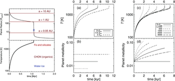
The red horizontal lines in the top left panel show the Hill radii [2] for several values of planet-star separation a, assuming M * = 1M⊙. When R p approaches R H from below, mass loss from the planet commences. Nayakshin & Lodato (Reference Nayakshin and Lodato2012) showed that the planet mass loss can be stable or unstable depending on the planet mass–radius relationship. For a molecular hydrogen planet with polytropic index n = 5/2, ζ p = −3 in equation (26) in the quoted paper, and the mass transfer is unstable. Physically, the planet expands rapidly (R p∝M −3 p for this n) as it loses mass. This expansion and mass loss is a runaway process until the core starts to dominate the mass of the planet, at which point the planet radius–mass relation changes. The mass loss then slows down and eventually stops. In the coupled disc–planet models below (Section 8), a simplifying assumption that mass transfer begins when R p exceeds R H and instantaneously unbinds the planet is made.
The top left panel of Figure 10 shows that pre-collapse planets can be disrupted at separations from a ~ 1 to tens of AU from the host star. Survival of a gas fragment as a giant planet at separations of ≲ a few AU requires the fragment to undergo second collapse before it migrates into the inner disc.
6.2. Radiative contraction
Given that migration times of gas fragments can be as short as t mig ~ 104 yrs (Section 4.2), survival of any Jupiter mass gas clumps that cools radiatively, as in Figure 10, in the inner few AU disc appears very unlikely. This is confirmed by Forgan & Rice (Reference Forgan and Rice2013b), see Section 8.2. Furthermore, Vazan & Helled (Reference Vazan and Helled2012) considered a more realistic setup in which pre-collapse planets are embedded in a protoplanetary disc at selected distances from the star. They found that disc irradiation of the planet further slows down the contraction and may even reverse it, heating the planet up, puffing it up, and eventually unbinding it (see also Cameron et al. Reference Cameron, Decampli and Bodenheimer1982). This ‘thermal bath’ effect makes the challenge of having any moderately massive gas fragments, M p ≲ a few MJ, to collapse in the inner ~ 10 AU via radiative cooling nearly impossible.
Finally, Helled & Bodenheimer (Reference Helled and Bodenheimer2011) pointed out that, without grain growth and sedimentation, gas giant planets formed by gravitational instability and cooling radiatively would anti-correlate with metallicity of the parent star, [M/H], which contradicts the observed positive correlation (Fischer & Valenti Reference Fischer and Valenti2005). Assuming that dust opacity is proportional to metal mass in the planet, they found that higher dust opacity pre-collapse fragments naturally take longer to cool radiatively.
However, the full picture may be more complex if grain opacity is significantly reduced by grain growth, see Helled & Bodenheimer (Reference Helled and Bodenheimer2011). For example, it is not impossible that grain opacity in high metallicity gas clumps would be actually smaller since grain growth time scales are shorter. If that were the case, then gas clumps would contract and collapse more rapidly in high metallicity environments and that could give rise to a positive metallicity correlation, perhaps similar to the one observed. As pointed out in Nayakshin (Reference Nayakshin2015c), this scenario appears to be disfavoured for a number of reasons but it should not be entirely ruled out. More sophisticated models of protoplanetary clumps, perhaps accounting for a partial gas mass loss from the clumps, are needed for a more definitive conclusion.
6.3. Pebble accretion
As already discussed in Section 5.1, grains that are moderately weakly coupled to gas via aerodynamical friction (a few mm to a few cm in size) are captured by a dense body or fragment embedded into the disc (Rice et al. Reference Rice, Armitage, Wood and Lodato2006; Johansen & Lacerda Reference Johansen and Lacerda2010; Ormel & Klahr Reference Ormel and Klahr2010; Boley & Durisen Reference Boley and Durisen2010).
Nayakshin (Reference Nayakshin2015a) studied contraction of coreless gas fragments of different metallicities, i.e., the limit when grains do not get locked into the core because the fragment is too hot or when the sedimentation process is too long. It was found that if Z = const within the fragment, then fragments of higher metallicity collapse slower, confirming results of Helled & Bodenheimer (Reference Helled and Bodenheimer2011). However, if the fragment metallicity was increased gradually, by adding grains to the fragment, then the larger the pebble accretion rate, the faster the fragment was found to contract.
The panels (a) and (c) of Figure 10 show the central temperature of gas fragments of initial mass M p0 = 4MJ, with an initial T c = 100 K and the dust opacity reduced by a factor of 10 from the interstellar values (Zhu et al. Reference Zhu, Hartmann and Gammie2009). Panels (b) and (d) show metallicity evolution of the fragments.
In the figure, the constant Z cases are presented in panels (a,b), whereas panels (c,d) show the cases where metals are added to the planet at a constant rate, parameterised by parameter t
z: $\dot{M}_{\rm Z} = \text{d}M_{\rm Z}/\text{d}t = \text{Z}_\odot M_{\rm p0}/t_{\rm z}$
, where
$\dot{M}_{\rm Z} = \text{d}M_{\rm Z}/\text{d}t = \text{Z}_\odot M_{\rm p0}/t_{\rm z}$
, where $M_{\text{Z}}$
is the mass of metals inside the planet, and M
p0 is the mass of the planet at time t = 0. The initial metallicity for all the cases on the right is Solar,
$M_{\text{Z}}$
is the mass of metals inside the planet, and M
p0 is the mass of the planet at time t = 0. The initial metallicity for all the cases on the right is Solar, $Z = \text{Z}_\odot$
. Grain growth and settling into the core is turned off, so that fragments keep uniform composition. The full problem with grain growth and settling into the core is non-linear and is considered in Section 7.5.
$Z = \text{Z}_\odot$
. Grain growth and settling into the core is turned off, so that fragments keep uniform composition. The full problem with grain growth and settling into the core is non-linear and is considered in Section 7.5.
Physically, addition of pebbles to the fragment may be likened to addition of ‘dark’ mass to the planet. The total energy of the fragment, E tot, evolves in time according to
 $$\begin{equation}
{\text{d} E_{\rm tot}\over \text{d}t} = - L_{\rm rad} - L_{\rm peb} \;,
\end{equation}$$
$$\begin{equation}
{\text{d} E_{\rm tot}\over \text{d}t} = - L_{\rm rad} - L_{\rm peb} \;,
\end{equation}$$
where L rad and L peb are respectively, the radiative luminosity of the planet, and the potential energy gain due to pebble accretion, defined as a luminosity:
 $$\begin{equation}
L_{\rm peb} = {G M_{\rm p}\dot{M}_z \over R_{\rm p}}\;.
\end{equation}$$
$$\begin{equation}
L_{\rm peb} = {G M_{\rm p}\dot{M}_z \over R_{\rm p}}\;.
\end{equation}$$
This term is negative since the potential energy change of the fragment as pebbles are added is negative. For moderately massive fragments, M p ≲ a few MJ, radiative luminosity is small, as we have seen, and so pebble accretion is the dominant effective cooling mechanism (Nayakshin Reference Nayakshin2015a).
In reality, the fragment does not cool—it just becomes more massive without a gain in kinetic or thermal energy, and hence must contract. Assuming the planet to be a polytropic sphere of gas with adiabatic index n with an admixture of grains treated as dark mass not contributing to pressure or entropy, it is possible to obtain an analytic solution for how the central temperature of the sphere evolves when its metallicity is increased (Nayakshin Reference Nayakshin2015a):
 $$\begin{equation}
T_{\rm c} = T_0 \left( {M_{\rm p}\over M_{\rm p0}}\right)^{6\over 3-n} = T_0 \left[{1-Z_0\over 1-Z}\right]^{6\over 3-n}\;,
\end{equation}$$
$$\begin{equation}
T_{\rm c} = T_0 \left( {M_{\rm p}\over M_{\rm p0}}\right)^{6\over 3-n} = T_0 \left[{1-Z_0\over 1-Z}\right]^{6\over 3-n}\;,
\end{equation}$$
where Z 0 and T 0 are initial metallicity and central temperature of the planet. In the limit Z 0 < Z ≪ 1, it can be further simplified. (1 − Z 0)/(1 − Z) ≈ 1 + (Z − Z 0), and using the identity (1 + x) b ≈ exp(bx) valid for x ≪ 1:
 $$\begin{equation}
T_{\rm c} = T_0 \exp \left[ {6\Delta Z\over 3-n}\right]\;,
\end{equation}$$
$$\begin{equation}
T_{\rm c} = T_0 \exp \left[ {6\Delta Z\over 3-n}\right]\;,
\end{equation}$$
where ΔZ = Z − Z 0. Clearly, if 6/(3 − n) ≫ 1, then the planet heats up (contracts) very rapidly with addition of grains. In particular, for diatomic molecules of H2, γ = 7/5, or n = 5/2, so
 $$\begin{equation}
T_{\rm c} = T_0 \exp \left[ {12 \Delta Z}\right] = T_0 \exp \left[ {0.18 {\Delta Z\over \text{Z}_\odot }}\right] \;.
\end{equation}$$
$$\begin{equation}
T_{\rm c} = T_0 \exp \left[ {12 \Delta Z}\right] = T_0 \exp \left[ {0.18 {\Delta Z\over \text{Z}_\odot }}\right] \;.
\end{equation}$$
This predicts that increasing the metallicity of the fragment by the factor of ~ 6 increases its central temperature by factor of e, taking the pre-collapse fragment much closer to second collapse.
6.4. Metallicity correlations as function of M p
The time it takes for an isolated gas fragment of mass M p to reach central temperature of T c ≳ 2000 K and collapse via H2 dissociation is (very approximately)
 $$\begin{equation}
t_{\rm rad} \sim 1 \hbox{ Myr } \left({1{\,{\rm M}_{\rm J}}\over M_{\rm p}}\right)^2 \left( {Z\over \text{Z}_\odot }\right)\;,
\end{equation}$$
$$\begin{equation}
t_{\rm rad} \sim 1 \hbox{ Myr } \left({1{\,{\rm M}_{\rm J}}\over M_{\rm p}}\right)^2 \left( {Z\over \text{Z}_\odot }\right)\;,
\end{equation}$$
where the interstellar grain opacity is assumed (e.g., see Figure 1 in Nayakshin Reference Nayakshin2015a). This equation neglects energy release by the core, which is justifiable as long as the core is less massive than a few Earth masses (Section 7.5).
The migration time in the type I regime is as short as ~ 104 yrs [cf. equation (7)]. When the planets reach the inner ~ 10 AU disc, where the disc is usually not self-gravitating, with Toomre’s Q ≫ 1, more massive planets tend to open gaps and migrate in the slower type II regime. The migration time in that regime is typically ≳ 105 yrs.
Thus, radiative collapse is too slow to beat migration, and hence pebble accretion is needed to speed it up, for gas fragments of a moderate mass, M p ≲ 3MJ. Since more pebbles are bound to be present in higher metallicity discs, the moderately massive gas giants are expected to correlate positively with [M/H] of the host. For planets more massive than ~ 5MJ, the radiative cooling time is comparable or shorter than the migration time. This suggests that massive gas giant planets may collapse radiatively at low [M/H] before they migrate in and are tidally disrupted. At even higher masses, M p ≳ 10MJ, including the BD regime, fragments always collapse more rapidly via radiation than they migrate in, whatever the metallicity of the host disc.
This predicts that metallicity correlations of giant planets should undergo a fundamental change around the mass of ~ 5MJ.
6.5. Second disruptions at a ≲ 0.1 AU
Post-collapse (second core stage) planets are denser than pre-collapse planets by a few orders of magnitude, so they are much less likely to be tidally compromised. However, as seen from the left panel of Figure 10, there is a brief period of time when a contracting post-collapse gas giant planet may be disrupted at separation a ≲ 0.1 AU. In Nayakshin (Reference Nayakshin2011c), a toy model for both the disc and the planet was used to argue that many massive cores found by the Kepler satellite in abundance at separation of ~ 0.1 from their host stars could be made via such ‘second’ disruptions. Based on the toy model, it was shown that post-collapse planets migrating early on, when the disc accretion rate is large, $\dot{M} \gtrsim 10^{-7} {\,{\rm M}_{\odot }}$
yr−1, may be disrupted at characteristic distance of a ≲ 0.1 AU, whereas planets migrating later, when the disc accretion rate is much smaller are more likely to be sufficiently compact to avoid the disruption.
$\dot{M} \gtrsim 10^{-7} {\,{\rm M}_{\odot }}$
yr−1, may be disrupted at characteristic distance of a ≲ 0.1 AU, whereas planets migrating later, when the disc accretion rate is much smaller are more likely to be sufficiently compact to avoid the disruption.
Nayakshin & Lodato (Reference Nayakshin and Lodato2012) improved on this calculation by using a realistic 1D time-dependent disc model, although still using a very simple (constant effective temperature) cooling model for the planet. A rich set of disc–planet interaction behaviour was found, which is not entirely surprising since the disc can exchange with the planet not only the angular momentum but also mass. The disc may be also switching between the cold molecular H and the hot ionised H stable branches of the disc (Meyer & Meyer-Hofmeister Reference Meyer and Meyer-Hofmeister1981, Reference Meyer and Meyer-Hofmeister1984; Bell & Lin Reference Bell and Lin1994), resulting in large increases or decreases in the accretion rate. This may lead to the planet’s migration type changing from type II to type I or vice versa. Importantly, if the planet mass loss proceeds mainly via the Lagrangian L1 point and the migration type is II, then the planet migrates outward during the intense mass loss phases.
Figure 11 shows an example calculation from Nayakshin & Lodato (Reference Nayakshin and Lodato2012) in which a second collapse fragment of mass M 0 = 10MJ is inserted into a protoplanetary disc at a 0 = 1 AU. Initially, the planet is much smaller than its Hills radius, so the mass loss rate is zero. The planet opens a very deep gap in the disc, cutting off mass supply to the inside disc, which empties onto the star. This creates a gas-free hole inside the planet orbit. As the planet migrates inward, both R p and R H shrink with time, but the planet contraction time is far longer than its migration time of ~ 103 yrs (this is the case of a very massive disc). Therefore, the Hill radius catches up with R p when the planet–star separation a ~ 0.1 AU.
A coupled evolution of the disc and the migrating planet from Nayakshin & Lodato (Reference Nayakshin and Lodato2012). Top panel: Planet separation from the star (solid) and planet’s mass in units of 10MJ (dashed). Middle: Planet radius (R p, solid) and planet Hills radius (dashed). Bottom: Accretion rate onto the star (solid) and the mass loss rate of the planet (dotted).

When R H − R p becomes comparable with the planetary atmosphere height-scale, the planet starts to lose mass rapidly via L1 point. This fills the disc inward of the planet with material lost by the planet, and accretion onto the star resumes at a very high rate. Since the viscous time is short at such small distances from the star, accretion rate onto the star matches the mass loss rate by the planet (except for very brief periods of time). An FU Ori like outburst commences which is powered by the star devouring the material shaved off the planet. At the beginning of the outburst, a quasi equilibrium is established: The star accretes the planet material at exactly the rate at which it is lost by the planet. The mass of the planet starts to decrease rapidly (see the dashed curve in the top panel of the figure). The equilibrium is however soon destabilised as rapid transitions between the low and the high temperature states in the disc occur in the gap region of the disc, and hence the disc switches between the two states much more rapidly than could be expected, leading to the complex quasi-periodic behaviour seen in the lower panel of Figure 11. Such rapid transitions may be related to the less violent and shorter duration outbursting sources known as EXORs (Herbig Reference Herbig and Reipurth1989; Sicilia-Aguilar et al. Reference Sicilia-Aguilar2008; Lorenzetti et al. Reference Lorenzetti2009). The long duration outbursts seen in other examples in Nayakshin & Lodato (Reference Nayakshin and Lodato2012) may correspond to the high luminosity long duration classical FU Ori events, as suggested earlier by Vorobyov & Basu (Reference Vorobyov and Basu2005, Reference Vorobyov and Basu2006), Boley et al. (Reference Boley, Hayfield, Mayer and Durisen2010).
The planet eventually loses so much mass that the gap closes; this triggers an even faster mass loss rate, producing the large spike in the accretion rate at t ≈ 2600 yrs in the bottom panel of Figure 11. The second disruptions also leave behind solid cores assembled within the planets during pre-collapse stage. This may lead to a metallicity signature in the period distribution of small planets (see Section 9.7).
7 CORES IN TIDAL DOWNSIZING SCENARIO
7.1. Grain sedimentation inside the fragments
Grain sedimentation time-scales can be made assuming for simplicity constant density within the gas fragment (Boss Reference Boss1998). Combining the Epstein and the Stokes drag regimes, it is possible to derive [equation (41) in Nayakshin (Reference Nayakshin2010b)] the sedimentation velocity for a spherical grain of radius ag and material density ρ a :
 $$\begin{equation}
v_{\rm sed} = \frac{4 \pi G \rho _{\text{a}} a_{\text{g}} R}{3 c_{\text{s}}} {\lambda + a_{\text{g}} \over \lambda } \left(1 + f_{\rm g}\right)\;,
\end{equation}$$
$$\begin{equation}
v_{\rm sed} = \frac{4 \pi G \rho _{\text{a}} a_{\text{g}} R}{3 c_{\text{s}}} {\lambda + a_{\text{g}} \over \lambda } \left(1 + f_{\rm g}\right)\;,
\end{equation}$$
where λ = 1/(nσH2) is the mean free path for hydrogen molecules, n and σH2 ≈ 10−15cm2 are the gas density and collision cross section, R is the distance from the centre of the fragment, and $c_{\text{s}}$
is the sound speed. The dimensionless factor f
g is the mass fraction of grains in the fragment interior to radius R; it is initially small, f
g ~ 0.01, but may become greater than unity when grains sediment to the fragment centre.
$c_{\text{s}}$
is the sound speed. The dimensionless factor f
g is the mass fraction of grains in the fragment interior to radius R; it is initially small, f
g ~ 0.01, but may become greater than unity when grains sediment to the fragment centre.
For a reference, at ag = 1 cm, v sed ≈ 1.2 m s−2 in the Epstein’s regime (ag ≪ λ) for R = 1 AU and fragment temperature of 300 K. Note that v sed∝ag , so that large grains fall to the centre faster. Sweeping smaller grains in their path as they fall, larger grains grow by accretion of the smaller ones (see, e.g., Dullemond & Dominik Reference Dullemond and Dominik2005). The time to reach the centre from radius R is independent of R:
 $$\begin{equation}
t_{\rm sed}= \frac{R}{v_{\rm sed}} \approx 5 \times 10^3 \;\hbox{yrs}\; \left({3\; {\rm g \; cm}^{-2}\over \rho _{\text{a}} a}\right) {\lambda \over \lambda + a_{\text{g}}}
\end{equation}$$
$$\begin{equation}
t_{\rm sed}= \frac{R}{v_{\rm sed}} \approx 5 \times 10^3 \;\hbox{yrs}\; \left({3\; {\rm g \; cm}^{-2}\over \rho _{\text{a}} a}\right) {\lambda \over \lambda + a_{\text{g}}}
\end{equation}$$
for f g ≪ 1. We observe that this timescale is shorter than the planet migration time for grains with size ag ≳ 1 cm. This opens up the possibility of making solid cores within the fragment prior to its tidal disruption (McCrea & Williams Reference McCrea and Williams1965; Decampli & Cameron Reference Decampli and Cameron1979; Boss Reference Boss1998; Boley et al. Reference Boley, Hayfield, Mayer and Durisen2010). Numerical modelling shows that convection presents a significant hurdle to grain sedimentation (Helled, Podolak, & Kovetz Reference Helled, Podolak and Kovetz2008; Helled & Schubert Reference Helled and Schubert2008, and Section 8.3.1).
7.2. Gravitational collapse of the ‘grain cluster’
The main difficulty in forming planets by a direct gravitational collapse of the solid component in the protoplanetary disc is the differential shear (Goldreich & Ward Reference Goldreich and Ward1973) and turbulence in the disc (Weidenschilling Reference Weidenschilling1980). Just a tiny fraction of the circular motion of the protoplanetary disc, v K = 30 km s−2 at 1 AU, transferred into gas turbulent motions is sufficient to result in the maximum mass made by the gravitational collapse being negligibly small compared to a planet mass (see Section 7.3 in Nayakshin Reference Nayakshin2011a).
In Tidal Downsizing, making planetary mass cores by direct collapse of the grain component inside a gas fragment may be simpler. Once a significant fraction of the fragment grains sediment into the central region of the fragment, grains start to dominate the mass density there, so that f g ≫ 1 in the central region (see Figure 7 here, and also Figures 2 or 4 in Nayakshin Reference Nayakshin2010b). Gas fragments found in simulations of self-gravitating discs usually rotate approximately as solid bodies, making rotational velocities in their centres rather small (Nayakshin Reference Nayakshin2011c); thus rotation is not likely to prevent gravitational collapse of the grain cluster (the region where f g ≫ 1) entirely. In Nayakshin (Reference Nayakshin2010b), Section 3.6.2, evolution of a single size grain population within a constant density gas background was considered. If was shown that when the fragment grains sediment within the radius
 $$\begin{equation}
R_{\rm gc} \approx 0.1 R_{\rm p} \left({f_{\rm g}\over 0.01}\right)^{1/2}\;,
\end{equation}$$
$$\begin{equation}
R_{\rm gc} \approx 0.1 R_{\rm p} \left({f_{\rm g}\over 0.01}\right)^{1/2}\;,
\end{equation}$$
where f g is the initial grain mass fraction in the fragment, and R p is the planet radius, gas pressure gradient is no longer able to counteract the collapse. The grain cluster may then collapse into a dense core.
7.3. Hierarchical formation of smaller bodies
Many astrophysical systems follow the hierarchical fragmentation scenario first suggested for galaxies by Hoyle (Reference Hoyle1953). In his model, as a very massive gas cloud contracts under its own weight, smaller and smaller regions of the cloud become self-gravitating. The Jeans mass in the cloud is $M_{\rm Jeans} \sim c_{\text{s}}^3/(G^3 \rho )^{1/2}$
, where
$M_{\rm Jeans} \sim c_{\text{s}}^3/(G^3 \rho )^{1/2}$
, where $c_{\text{s}}$
and ρ are the gas sound speed and density, respectively. The Jeans mass is originally equal to that of the cloud (galaxy). Provided that
$c_{\text{s}}$
and ρ are the gas sound speed and density, respectively. The Jeans mass is originally equal to that of the cloud (galaxy). Provided that $c_{\text{s}}$
remains roughly constant due to cooling, increasing ρ during the collapse implies that smaller sub-parts of the cloud start to satisfy the condition M < M
Jeans, where M is mass of the sub-part. These regions can then collapse independently from the larger system. This process continues, eventually making star clusters, groups of stars, individual stars, and perhaps even gas giant planets on the smallest scales where the hierarchical collapse stops because gas can no longer cool effectively below the opacity fragmentation limit (Rees Reference Rees1976).
$c_{\text{s}}$
remains roughly constant due to cooling, increasing ρ during the collapse implies that smaller sub-parts of the cloud start to satisfy the condition M < M
Jeans, where M is mass of the sub-part. These regions can then collapse independently from the larger system. This process continues, eventually making star clusters, groups of stars, individual stars, and perhaps even gas giant planets on the smallest scales where the hierarchical collapse stops because gas can no longer cool effectively below the opacity fragmentation limit (Rees Reference Rees1976).
Is there a similar hierarchy of collapse scales for the grains sedimenting down inside the gas fragments?
Consider an off-centre spherical region with radius ΔR and gas density ρ somewhat higher than the background density. Grains inside the region will sediment towards the centre of that region on a timescale Δt independent of ΔR:
 $$\begin{equation}
\Delta t \approx \frac{3 c_{\text{s}} \mu }{4 \pi G \rho _{\text{a}} a_{\text{g}}^2 \sigma _{\rm H2}} \; {1 \over \rho (1 + f_{\rm g})}\;,
\end{equation}$$
$$\begin{equation}
\Delta t \approx \frac{3 c_{\text{s}} \mu }{4 \pi G \rho _{\text{a}} a_{\text{g}}^2 \sigma _{\rm H2}} \; {1 \over \rho (1 + f_{\rm g})}\;,
\end{equation}$$
where f
g > 1 is the local grain concentration and it is assumed that $\lambda \ll a_{\text{g}}$
. From this, we see that if the total density in the perturbed region, ρ(1 + f
g), is greater than that of the surroundings, it will collapse more rapidly than the whole grain cluster considered in Section 7.2. The collapse accelerates with time: Δt is inversely proportional to density and the density increases as the perturbation collapses. Thus, the grains in this region are able to collapse into an independent solid body before the whole grain cluster collapses.
$\lambda \ll a_{\text{g}}$
. From this, we see that if the total density in the perturbed region, ρ(1 + f
g), is greater than that of the surroundings, it will collapse more rapidly than the whole grain cluster considered in Section 7.2. The collapse accelerates with time: Δt is inversely proportional to density and the density increases as the perturbation collapses. Thus, the grains in this region are able to collapse into an independent solid body before the whole grain cluster collapses.
This argument suggests that perturbations of all sizes can collapse. A very small ΔR region collapses slowly since the collapse velocity, proportional to ΔR, is quite small. However, the collapse time is as short as that for a much more extended perturbation. Taken at face value, this would imply that even tiny solid bodies, with final post-collapse radius a fin as small as ≲ 1 m could form via this process. However, in practice, there is another limit to consider. A small body born by collapse of a small perturbation is very likely to be inside of a larger perturbation (which in itself may be a part of a yet bigger one). Therefore, the small body will be incorporated into a larger collapsing system unless the body can decouple dynamically from the larger system.
Consider now a post-collapse body of radius $a_{\text{b}}$
, and material density
$a_{\text{b}}$
, and material density $\rho _{\text{b}} \sim 1$
g cm−3. Since the body is inside the region where f
g > 1, we can neglect aerodynamical friction with the gas and consider only interaction of the body with grains in the region. The body may be able to decouple from the bulk of the grains collapsing into the core if the stopping distance of the body is larger than R
gc. This requires that the column depth of the body
$\rho _{\text{b}} \sim 1$
g cm−3. Since the body is inside the region where f
g > 1, we can neglect aerodynamical friction with the gas and consider only interaction of the body with grains in the region. The body may be able to decouple from the bulk of the grains collapsing into the core if the stopping distance of the body is larger than R
gc. This requires that the column depth of the body
 $$\begin{equation}
\Sigma _{\text{b}} = \rho _{\text{b}} a_{\text{b}} > \rho _{\rm gc} R_{\rm gc} = \rho _0 R_{\rm f} \approx {M_{\rm f}\over \pi R_{\rm f}^2}
\end{equation}$$
$$\begin{equation}
\Sigma _{\text{b}} = \rho _{\text{b}} a_{\text{b}} > \rho _{\rm gc} R_{\rm gc} = \rho _0 R_{\rm f} \approx {M_{\rm f}\over \pi R_{\rm f}^2}
\end{equation}$$
is larger than the column depth of the parent gas fragment. Introducing a mean temperature of the fragment as $T_{\rm p} \approx GM_{\rm p}\mu /(3 k_{\text{b}} R_{\rm p})$
, we obtain the minimum size of an object that can separate itself out of the core:
$T_{\rm p} \approx GM_{\rm p}\mu /(3 k_{\text{b}} R_{\rm p})$
, we obtain the minimum size of an object that can separate itself out of the core:
 $$\begin{equation}
a_{\rm min} = 3.7 \hbox{ km } T_3^2 {1{\,{\rm M}_{\rm J}}\over M_{\rm p}} \rho _b^{-1}\;.
\end{equation}$$
$$\begin{equation}
a_{\rm min} = 3.7 \hbox{ km } T_3^2 {1{\,{\rm M}_{\rm J}}\over M_{\rm p}} \rho _b^{-1}\;.
\end{equation}$$
This is in the asteroid size range. Finally, we should demand that the body is able to resist gas drag for a long enough time after the core is formed (when the grains in the collapsing grain cluster are mainly incorporated into the core). This problem has been examined in Nayakshin & Cha (Reference Nayakshin and Cha2012), also leading to a minimum size in the range of $1\text{--}10$
km.
$1\text{--}10$
km.
Figure 12 shows two snapshots from a simulation (Nayakshin 2016, in preparation) of grain-loaded polytropic clump. The figure shows gas surface density (colours) for a slice between − 0.1 AU < y < 0.1 AU and (x, z) as shown. The blue squares on top of the gas mark positions of individual grains. The simulation is started with a relaxed polytropic gas clump of mass 3MJ, adiabatic index γ = 7/5, and central temperature $T_{\text{c}} = 500$
K. The clump is instantaneously loaded with grains of size a
g = 10 cm of total mass of 10% of the clump mass, uniformly spread inside a spherically symmetric shell between radii of 0.8R
p and R
p, where R
p is the planet radius. The initial configuration is displayed in the left panel of Figure 12.
$T_{\text{c}} = 500$
K. The clump is instantaneously loaded with grains of size a
g = 10 cm of total mass of 10% of the clump mass, uniformly spread inside a spherically symmetric shell between radii of 0.8R
p and R
p, where R
p is the planet radius. The initial configuration is displayed in the left panel of Figure 12.
Simulations of a polytropic gas clump (colours) of mass 3MJ instantaneously loaded with 0.3MJ worth of 10-cm sized grains (blue dots) distributed in a spherical outer shell. Left and right panels show the initial condition and time t = 7 yrs, respectively. Note the development of Raileigh–Taylor instability in which high grain concentration fingers sediment non-spherically. See text in Section 7.3 for more detail.

The right panel of the figure shows what happens with the planet and grains at time t = 7 yrs (which corresponds to about three dynamical times for the initial clump). Importantly, grain sedimentation process is not spherically symmetric, with ‘fingers’ of higher grain concentration materials protruding inwards. Undoubtedly, the development of the infalling filaments is driven by the Rayleigh–Taylor instability. These preliminary results indicate that there may be additional physical reasons for development of many rather than one grain concentration centres, lending support to the hypothesis that pre-collapse gas fragments may be sites of both core and planetesimal formation. Also, note that the fragment is contracting as predicted by the spherically symmetric model (Nayakshin Reference Nayakshin2015a), although its latter evolution strongly depends on whether a massive core is formed in the centre.
7.4. Core composition
A gas fragment of Solar composition (Lodders Reference Lodders2003) contains
 $$\begin{equation}
M_{\rm Z} = 0.015 M_{\rm f} \approx 4.5 {\,{\it M}_{\oplus }}\; \frac{Z}{0.015} \; {M_{\rm p}\over {\,{\rm M}_{\rm J}}}
\end{equation}$$
$$\begin{equation}
M_{\rm Z} = 0.015 M_{\rm f} \approx 4.5 {\,{\it M}_{\oplus }}\; \frac{Z}{0.015} \; {M_{\rm p}\over {\,{\rm M}_{\rm J}}}
\end{equation}$$
of total mass in astrophysical metals. A third of this mass is in water which is very volatile—vaporisation temperature $T_{\rm vap}\sim 150\text{--}200$
K for the relevant range in gas pressure.
$T_{\rm vap}\sim 150\text{--}200$
K for the relevant range in gas pressure.
Furthermore, another third of the grain mass is in volatile organics, commonly referred to as ‘CHON’, which is a mnemonic acronym for the four most common elements in living organisms: carbon, hydrogen, oxygen, and nitrogen. For this review, CHON is organic material other than water. CHON is a frequently used component in planet formation models (e.g., Pollack et al. Reference Pollack1996; Helled et al. Reference Helled, Podolak and Kovetz2008). The composition of CHON is set to be similar to that of the grains in Comet Halley’s coma (Oberc Reference Oberc2004). CHON vaporisation temperature is higher than that of water but is still rather low, $T_{\rm vap}\sim 350\text{--}450$
K for the range of gas pressures appropriate for the interiors of pre-collapse fragmentsFootnote
2
.
$T_{\rm vap}\sim 350\text{--}450$
K for the range of gas pressures appropriate for the interiors of pre-collapse fragmentsFootnote
2
.
Given the fact that fragments migrate in as rapidly as ~ 104 yrs, the core must form similarly quickly or else the fragment will either collapse and become a second core or be disrupted, at which point core growth terminates. In practice, a rapid core formation requires that gas fragments are compact and dense, but this also means that water and ice and CHON are unlikely to be able to sediment into the centre because the fragments are too hot (Helled & Schubert Reference Helled and Schubert2008). Cores made by Tidal Downsizing are hence likely to be rock-dominated Footnote 3 . This is significantly different from the classical CA where massive cores are most naturally assembled beyond the ice line and are thus ice-dominated (Pollack et al. Reference Pollack1996; Coleman & Nelson Reference Coleman and Nelson2016). In Section 10.2, we shall discuss current observations of core compositions in light of these differences between the two theories.
A Solar composition Jupiter mass fragment could only make a rocky core of mass M core ~ 1.5M ⊕ if all refractory grains sediment to its centre. More massive gas fragments could be considered (as done by Nayakshin Reference Nayakshin2010b, Reference Nayakshin2011a) but such fragments contract radiatively very rapidly, making sedimentation of even refractory grains difficult. Thus, to make a massive solid core, M core ≳ 10M ⊕, metal enrichment of fragments, such as pebble accretion or metal enrichment at birth (Boley & Durisen Reference Boley and Durisen2010; Boley et al. Reference Boley, Helled and Payne2011), is necessary.
7.5. Core feedback and maximum mass
As the core is assembled, some of its gravitational potential energy is radiated into the surrounding gas envelope. How much exactly is difficult to say since the opacity, equation of state, and even the dominant means of energy transport for hot massive planetary cores are not well understood yet (Stamenković et al. Reference Stamenković, Noack, Breuer and Spohn2012). The problem is also highly non-linear since the overlying gas envelope structure may modify the energy loss rate of the core, and the temperature of the surrounding gas in turn depends on the luminosity of the core (Hori & Ikoma Reference Hori and Ikoma2011; Nayakshin, Helled, & Boley Reference Nayakshin, Helled and Boley2014).
7.5.1. Analytical estimates
Nevertheless, assuming that a fraction $0 < \xi _{\text{c}} \lesssim 1$
of CA energy, E
core ~ GM
2
core/R
core, is released into the fragment and that the latter cannot radiate it away quickly, the core mass is limited by the following order of magnitude estimate:
$0 < \xi _{\text{c}} \lesssim 1$
of CA energy, E
core ~ GM
2
core/R
core, is released into the fragment and that the latter cannot radiate it away quickly, the core mass is limited by the following order of magnitude estimate:
 $$\begin{equation}
\xi _{\text{c}} {G M_{\rm core}^2\over R_{\rm core}} \lesssim {G M_{\rm p}^2 \over R_{\rm p}}\;.
\end{equation}$$
$$\begin{equation}
\xi _{\text{c}} {G M_{\rm core}^2\over R_{\rm core}} \lesssim {G M_{\rm p}^2 \over R_{\rm p}}\;.
\end{equation}$$
Defining the escape velocity as $v_{\rm esc} = \sqrt{G M_{\rm p}/R_{\rm p}}$
,
$v_{\rm esc} = \sqrt{G M_{\rm p}/R_{\rm p}}$
,
 $$\begin{equation}
{M_{\rm core}\over M_{\rm p}} \lesssim {v_{\rm esc, p}^2 \over \xi _{\text{c}} v_{\rm esc, c}^2}
\end{equation}$$
$$\begin{equation}
{M_{\rm core}\over M_{\rm p}} \lesssim {v_{\rm esc, p}^2 \over \xi _{\text{c}} v_{\rm esc, c}^2}
\end{equation}$$
Since v
esc, p ~ 1 km s−1 and v
esc, c ≳ 10 km s−1, this yields $M_{\rm core}/M_{\rm p} \lesssim 0.01 \xi _{\text{c}}^{-1}$
. A more careful calculation, in which the fragment is treated as a polytropic sphere with index n = 5/2 yields the following maximum ‘feedback’ core mass (Nayakshin Reference Nayakshin2016b):
$M_{\rm core}/M_{\rm p} \lesssim 0.01 \xi _{\text{c}}^{-1}$
. A more careful calculation, in which the fragment is treated as a polytropic sphere with index n = 5/2 yields the following maximum ‘feedback’ core mass (Nayakshin Reference Nayakshin2016b):
 $$\begin{equation}
M_{\rm core} \le M_{\rm fb} = 5.8 {\,{\it M}_{\oplus }}\left({T_3 M_{\rm p} \over 1 {\,{\rm M}_{\rm J}}}\right)^{3/5} \rho _{\rm c}^{-1/5} \xi _{\text{c}}^{-1}\;,
\end{equation}$$
$$\begin{equation}
M_{\rm core} \le M_{\rm fb} = 5.8 {\,{\it M}_{\oplus }}\left({T_3 M_{\rm p} \over 1 {\,{\rm M}_{\rm J}}}\right)^{3/5} \rho _{\rm c}^{-1/5} \xi _{\text{c}}^{-1}\;,
\end{equation}$$
where $T_3 = T_{\text{c}}/(1\,000$
K) is the central temperature of the fragment and ρc is the core mean density in units of g cm − 3. T
3 cannot exceed ≈ 1.5 because at higher temperatures grains vaporise and the core stops growing via their sedimentation anyway. Also, although not necessarily clear from the analytic argument, fragments with masses higher than a few MJ are not normally able to hatch massive cores because they contact quickly radiatively (cf. Figure 18 in Nayakshin & Fletcher Reference Nayakshin and Fletcher2015, and also Section 6.2). Therefore, the factor in the brackets in equation (25) cannot actually exceed a few, leading to the maximum core mass of
$T_3 = T_{\text{c}}/(1\,000$
K) is the central temperature of the fragment and ρc is the core mean density in units of g cm − 3. T
3 cannot exceed ≈ 1.5 because at higher temperatures grains vaporise and the core stops growing via their sedimentation anyway. Also, although not necessarily clear from the analytic argument, fragments with masses higher than a few MJ are not normally able to hatch massive cores because they contact quickly radiatively (cf. Figure 18 in Nayakshin & Fletcher Reference Nayakshin and Fletcher2015, and also Section 6.2). Therefore, the factor in the brackets in equation (25) cannot actually exceed a few, leading to the maximum core mass of ${\sim }10\text{--}20{\,{\it M}_{\oplus }}$
.
${\sim }10\text{--}20{\,{\it M}_{\oplus }}$
.
7.5.2. Radiative hydrodynamics calculation
Numerical calculations are desirable to improve on these estimates. In Nayakshin (Reference Nayakshin2016b), a 1D radiative hydrodynamics (RHD) code of Nayakshin (Reference Nayakshin2014) is employed to study the evolution of a fragment accreting pebbles. Unlike the earlier study of core-less fragments in Nayakshin (Reference Nayakshin2015a), grain growth and sedimentation onto the core are allowed. The energy equation for the fragment [see equation (10)], now taking into account the energy release by the core, reads
 $$\begin{equation}
{\text{d} E_{\rm tot}\over \text{d}t} = - L_{\rm rad} + L_{\rm core} - L_{\rm peb} \;,
\end{equation}$$
$$\begin{equation}
{\text{d} E_{\rm tot}\over \text{d}t} = - L_{\rm rad} + L_{\rm core} - L_{\rm peb} \;,
\end{equation}$$
where the new term on the right-hand side, L core, is the core luminosity. This term is positive because energy release by the core injects energy into the gas envelope (the fragment).
In the experiments shown in this section, the initial cloud mass, metallicity, and central temperature are M
p = 1MJ, $Z= 1 \text{Z}_\odot$
, and 150 K, respectively. The metal loading timescale is set to t
z = 2000 yrs. Figure 13 compares two runs, one without grain growth and without core formation (so identical in setup to Nayakshin Reference Nayakshin2015a), and the other with grain growth and core formation allowed. Panel (a) of the figure shows in black colour the evolution of T
3, the central fragment temperature measured in 103 K, and the planet radius, R
p [AU], shown with blue curves. The solid curves show the case of the fragment with the core, whereas the dotted ones correspond to the core-less fragment.
$Z= 1 \text{Z}_\odot$
, and 150 K, respectively. The metal loading timescale is set to t
z = 2000 yrs. Figure 13 compares two runs, one without grain growth and without core formation (so identical in setup to Nayakshin Reference Nayakshin2015a), and the other with grain growth and core formation allowed. Panel (a) of the figure shows in black colour the evolution of T
3, the central fragment temperature measured in 103 K, and the planet radius, R
p [AU], shown with blue curves. The solid curves show the case of the fragment with the core, whereas the dotted ones correspond to the core-less fragment.
Panel (a) shows the gas fragment central temperature T 3 = T c/103 K, and planet radius, R p, versus time for simulations with (solid curves) and without (dotted) core formation, as described in Section 7.5.2. Panel (b) shows core luminosity, L core, pebble luminosity, L peb, and the radiative luminosity of the fragment as labelled. Panel (c): The core mass, M core, and the total metal content of the fragment.

Panel (b) of Figure 13 presents the three luminosities in equation (26). The dust opacity for this calculation is set to 0.1 times the interstellar opacityFootnote
4
at $Z=\text{Z}_\odot$
(Zhu et al. Reference Zhu, Hartmann and Gammie2009). This increases the importance of L
rad term by a factor of ~ 10; for the nominal grain opacity, L
rad would be completely negligible. Finally, panel (c) of Figure 13 shows the total metal mass in the planet and the core mass with the black and red curves, respectively.
$Z=\text{Z}_\odot$
(Zhu et al. Reference Zhu, Hartmann and Gammie2009). This increases the importance of L
rad term by a factor of ~ 10; for the nominal grain opacity, L
rad would be completely negligible. Finally, panel (c) of Figure 13 shows the total metal mass in the planet and the core mass with the black and red curves, respectively.
Consider first the core-less fragment. As the fragment contracts, L rad quickly becomes negligible compared to L peb. This is the pebble accretion dominated no-core regime studied in Section 6.3 and in Nayakshin (Reference Nayakshin2015a). The fragment contracts as it accretes pebbles.
In the case with the core, panel (a) shows that the fragment collapse reverses when L core exceeds L peb + L rad. By the end of the calculation, the gas envelope is completely unbound, with the final M core = 15.2M ⊕, consistent with equation (25). It is worth emphasising that the appropriate fragment disruption condition is not the luminosity of the core, which first exceeds the sum L peb + L rad when M core ≈ 10M ⊕, but the total energy released by the core. On the other hand, for a migrating planet, the fact that the fragment stopped contracting when the core reached ≈ 8M ⊕ may be sufficient to change the fate of the fragment as is it is more likely to be disrupted when it stops contracting.
7.5.3. Comparison to Core Accretion
In CA theory, the core is more massive and much more compact than the envelope in the interesting stage, that is before the atmosphere collapses (Mizuno Reference Mizuno1980; Pollack et al. Reference Pollack1996; Papaloizou & Terquem Reference Papaloizou and Terquem1999). Therefore, in this theory, L core ≫ L peb always, and so one can neglect L peb in equation (26). The luminosity of the core is an obstacle that needs to be overcome in CA before the atmosphere collapses. It is thought that grain growth reduces the opacity in the atmosphere by factors of ~ 100, so that the atmosphere can re-radiate the heat output of the core and eventually collapse (Pollack et al. Reference Pollack1996; Mordasini Reference Mordasini2013).
In Tidal Downsizing, there are two regimes in which the pre-collapse gas clump (planet) reacts to pebble accretion onto it differently. While the mass of the core is lower than a few M ⊕, the gas clump contracts because L core ≪ L peb. The latter is large because the gas envelope mass is very much larger than that of a pre-collapse CA planet. This is the regime studied in Nayakshin (Reference Nayakshin2015a, Reference Nayakshin2015b), where pebble accretion was shown to be the dominant effective contraction mechanism for moderately massive gas giants.
The second regime, when core mass exceeds ~ 5M ⊕, is analogous to CA. Here, the core luminosity is large and cannot be neglected. This effect was studied recently in Nayakshin (Reference Nayakshin2016b) and is equally key to Tidal Downsizing. Due to this, massive cores are not simply passive passengers of their migrating gas clumps (Section 7.5).
The roles of massive cores in Tidal Downsizing and CA are diagonally opposite.
7.6. Gas atmospheres of cores
Nayakshin et al. (Reference Nayakshin, Helled and Boley2014) studied formation of a dense gas envelope around the core. This effect is analogous to that of CA, although the envelope (called atmosphere here) is attracted not from the disc but from the surrounding gas fragment. Assuming hydrostatic and thermal equilibrium for the envelope of the core, the atmospheric structure was calculated inward starting from $r_{\text{i}} = G M_{\rm core}/c_\infty ^2$
, where c
∞ is the sound speed in the first core sufficiently far away from the core, so that its influence on the gas inside the fragment may be approximately neglected.
$r_{\text{i}} = G M_{\rm core}/c_\infty ^2$
, where c
∞ is the sound speed in the first core sufficiently far away from the core, so that its influence on the gas inside the fragment may be approximately neglected.
It was then shown that for given inner boundary conditions (gas pressure and temperature at $r_{\text{i}}$
), there exists a maximum core mass, M
crit, for which the hydrostatic solution exists. For core masses greater than M
crit, the atmosphere weight becomes comparable to M
core, and the iterative procedure with which one finds the atmosphere mass within radius
$r_{\text{i}}$
), there exists a maximum core mass, M
crit, for which the hydrostatic solution exists. For core masses greater than M
crit, the atmosphere weight becomes comparable to M
core, and the iterative procedure with which one finds the atmosphere mass within radius $r_{\text{i}}$
runs away to infinite masses. M
crit was found to vary from a few M
⊕ to tens of M
⊕.
$r_{\text{i}}$
runs away to infinite masses. M
crit was found to vary from a few M
⊕ to tens of M
⊕.
In Nayakshin et al. (Reference Nayakshin, Helled and Boley2014), it was suggested that the fragments in which the mass of the core reached M
crit will go through the second collapse quickly and hence become young gas giant planets. However, the steady state assumptions in Nayakshin et al. (Reference Nayakshin, Helled and Boley2014) may not be justified during collapse. Experiments (unpublished) with hydrodynamic code of Nayakshin (Reference Nayakshin2014) showed that when the atmospheric collapse happens, there is a surge in the luminosity entering $r_{\text{i}}$
from the inner hotter regions. This surge heats the gas up and drives its outward expansion. This reduces gas density at
$r_{\text{i}}$
from the inner hotter regions. This surge heats the gas up and drives its outward expansion. This reduces gas density at $r_{\text{i}}$
, causing the pressure at
$r_{\text{i}}$
, causing the pressure at $r_{\text{i}}$
to drop as well, halting collapse.
$r_{\text{i}}$
to drop as well, halting collapse.
If the fragment is sufficiently hot even without the core, e.g., 2000 − T c ≪ T c, then the presence of a massive core may be able to accelerate the collapse by compressing the gas and increasing the temperature in the central regions above 2 000 K. However, if the fragment managed to reach the near collapse state without the core being important, then it would seem rather fine tuned that the fragment would then need the core to proceed all the way into the second collapse. The fragment is already close to collapse, so presumably it can collapse without the help from the core.
Therefore, at the present, it seems prudent to discount the atmospheric collapse instability as an important channel for gas fragment collapse. While this conclusion on the importance of bound gas atmospheres near the solid cores differs from that of Nayakshin et al. (Reference Nayakshin, Helled and Boley2014), their calculation of the atmosphere structure and the mass of the gas bound to the core is still relevant. If and when the fragment is disrupted, the atmosphere remains bound to the core. This is how Tidal Downsizing may produce planets with atmospheres composed of volatiles and H/He (cf. Section 11.2).
8 POPULATION SYNTHESIS
Detailed numerical experiments such as those presented in the previous sections are very computationally expensive and can be performed for only a limited number of cases. This is unsatisfactory given the huge parameter space and uncertainties in the initial conditions and microphysics, and the fact that observations have now moved on from one planetary system to ~ a thousand.
A more promising tool to confront a theory with statistics of observed planets is population synthesis modelling (PSM; see Ida & Lin Reference Ida and Lin2004a). A widely held opinion ‘with enough free parameters everything can be fit’ could be justifiable only perhaps a decade ago. Now, with ~ O(100) observational constraints from the SS and exoplanets, population synthesis is becoming more and more challenging. A balanced view of population synthesis is that it cannot ever prove that a model is right, but experience shows that it can challenge theories strongly. It can also highlight differences between planet formation theories and point out areas where more observations and/or theory work is needed.
There is much to borrow from CA population synthesis (Ida & Lin Reference Ida and Lin2004b; Mordasini, Alibert, & Benz Reference Mordasini, Alibert and Benz2009a; Mordasini, Alibert, Benz, & Naef Reference Mordasini, Alibert, Benz and Naef2009b). It is quite logical to follow the established approaches to modelling the protoplanetary disc, but then differ in planet formation physics. A planet formation module of the population synthesis should evolve the planet-forming elements of the model, integrating their internal physics, and interaction with the disc via grains/gas mass exchange and migration. The outcome of a calculation is the mass, composition, location, and orbit of one or more planets resulting from such a calculation. By performing calculations for different initial conditions (e.g., disc mass or radial extent), one obtains distributions of observables that can then be compared to the observations.
8.1. Galvagni and Meyer model
Galvagni & Mayer (Reference Galvagni and Mayer2014) study was focussed on whether hot Jupiters could be accounted for by gas fragments rapidly migrating from the outer self-gravitating disc. This (pre-pebble accretion) study was based on 3D SPH simulations of pre-collapse gas fragment contraction and collapse by Galvagni et al. (Reference Galvagni2012), who used a prescription for radiative cooling of the fragments, and found that gas fragments may collapse up to two orders of magnitude sooner than found in 1D (e.g., Bodenheimer Reference Bodenheimer1974; Helled et al. Reference Helled, Podolak and Kovetz2008). Galvagni & Mayer (Reference Galvagni and Mayer2014) concluded that many of the observed hot Jupiters could actually be formed via Tidal Downsizing. The model did not include grain growth and sedimentation physics, thus not addressing core-dominated planets.
8.2. Forgan and Rice model
Forgan & Rice (Reference Forgan and Rice2013b) solved the 1D viscous time dependent equation for the disc, and introduced the disc photo-evaporation term. Their protoplanetary disc model is hence on par in complexity with some of the best CA population synthesis studies (e.g., Mordasini et al. Reference Mordasini, Alibert and Benz2009a, Reference Mordasini, Alibert, Benz, Klahr and Henning2012). Both icy and rocky grains were considered to constrain the composition of the cores assembled inside the fragments. Fragments were allowed to accrete gas from the protoplanetary disc. For the radiative cooling of gas fragments, analytical formulae from Nayakshin (Reference Nayakshin2010a) were employed, which have two solutions for dust opacity scaling either as κ(T)∝T or as κ(T)∝T 2, where T is the gas temperature. Forgan & Rice (Reference Forgan and Rice2013b) also allowed multiple gas fragments per disc to be followed simultaneously.
Forgan & Rice (Reference Forgan and Rice2013b) made four different population synthesis calculations, varying the opacity law, the disc migration rate and the assumptions about what happens with the disc beyond 50 AU after it produces fragments. Results of one of such population synthesis experiments are presented in Figure 14, showing the fragment mass at time t = 1 million yrs versus its separation from the star. The colour of the circles shows the core mass within the fragments.
Population synthesis results from Forgan & Rice (Reference Forgan and Rice2013b; the right panel of their Figure 10), showing the mass of the fragment versus its separation from the host star. Colours show the mass of the cores assembled inside the fragments.

The authors conclude that the model falls way short of explaining the data. Gas fragments are either disrupted well before they are able to enter the central few AU region, producing hardly any hot Jupiters, or accrete gas rapidly, becoming BDs and even more massive stellar companions to the host star. No massive cores are released into the disc because the fragments that are disrupted do not manage to make massive cores, and the fragments that do make massive cores are in the BD regime and are not disrupted.
8.3. Nayakshin (2015) model
In Nayakshin (Reference Nayakshin2015c, Reference Nayakshin2015d), pebble accretion onto precollapse gas fragments was added to population synthesis for the first time. The disc model is similar to that of Forgan & Rice (Reference Forgan and Rice2013b), but also includes the interaction of the planet with the disc as in Nayakshin & Lodato (Reference Nayakshin and Lodato2012). This means that the disc not only influences the planet but also receives the back torques from the planet, so that a gap and even a large inner hole can be self-consistently opened. If the planet is disrupted, its gas is deposited in the disc around the planet location. The disc photo-evaporation rate is a Monte Carlo variable and the limits are adjusted such as to ensure that the disc fraction decays with the age of the system as observed, e.g., $\propto \exp (-t/t_{\text{l}})$
, where
$\propto \exp (-t/t_{\text{l}})$
, where $t_{\text{l}} = 3$
Myr (Haisch et al. Reference Haisch, Lada and Lada2001).
$t_{\text{l}} = 3$
Myr (Haisch et al. Reference Haisch, Lada and Lada2001).
8.3.1. Grains and cores in the model
The internal physics of the fragments is modelled numerically rather than analytically. The fragments are strongly convective (Helled et al. Reference Helled, Podolak and Kovetz2008; Helled & Schubert Reference Helled and Schubert2008), which implies that a good approximation to the gaseous part of the fragment is obtained by assuming that it is in a hydrostatic balance and has a constant entropy. The entropy however evolves with time as the fragment cools or heats up. This is known as ‘follow the adiabats’ approach (e.g., Henyey et al. Reference Henyey, Forbes and Gould1964; Marleau & Cumming Reference Marleau and Cumming2014). The irradiation of the planet by the surrounding disc (the thermal ‘bath effect’, see Vazan & Helled Reference Vazan and Helled2012) is also included.
The gas density and temperature profiles within the fragment are solved for numerically. The dust evolution module of the code considers three grain species: rocks (combined with Fe), organics (CHON), and water. Grain growth, sedimentation, and convective grain mixing are included. Grains are shattered in fragmenting collisions when the sedimentation velocity is too high (e.g., Blum & Münch Reference Blum and Münch1993; Blum & Wurm Reference Blum and Wurm2008; Beitz et al. Reference Beitz2011). Finally, grains are vaporised if gas temperature exceeds vaporisation temperature for the given grain species.
Grains reaching the centre accrete onto the solid core. The initial core mass is set to a ‘small’ value (10−4
M
⊕). Growing core radiates some of its gravitational potential energy away, but a self-consistent model for energy transfer within the core is not yet possible due to a number of physical uncertainties (e.g., Stamenković et al. Reference Stamenković, Noack, Breuer and Spohn2012). For this reason, the energy release by the core is parameterised via the Kelvin–Helmholtz contraction time of the core, t
kh, which is set to be of order $t_{\rm kh}\sim 10^5\text{--}10^6$
yrs. The luminosity released by the core is injected into the fragment.
$t_{\rm kh}\sim 10^5\text{--}10^6$
yrs. The luminosity released by the core is injected into the fragment.
Figure 15 shows an example calculation of the internal structure of a gas fragment from PSM by Nayakshin (Reference Nayakshin2015c). Since the gas is hot in the inner part and cool in the outer parts, volatile grains (ice and CHON) are able to settle down only in the outer parts of the fragment. In contrast, rocky grains can sediment all the way into the core. This is best seen in the bottom panel (c) of the figure: Water ice grains are only large in the outermost ~ 5% of the fragment. Interior to this region, the planet is too hot so that water ice vaporises. Strong convective mixing then ensures that the ratio of the water volume density to the gas density is constant to a good degree (compare the blue dotted and the black solid curves in panel b of the figure) in most of the cloud. Similarly, CHON grains can grow and sediment in the outer ~ half of the fragment only. Note that in the region where CHON grains are large and can sediment, their density shows a significant concentration towards the central parts of the fragment.
Internal structure of a planet (at time t = 24450 yrs in simulation M1Peb3 from Nayakshin Reference Nayakshin2015c) as a function of total (gas plus metals, including the core) enclosed mass. Panel (a) shows the temperature, Lagrangian radius (in units of AU), and local metallicity, z(M). Panel (b) shows gas (solid) and the three grain metal species density profiles, while panel (c) shows the species’ grain size, a gr.

The density of rocky grains is very strongly peaked in Figure 15, cf. the red dash-dotted curve in panel (b). In fact, most of the silicates are locked into the central core, and only the continuing supply of them from the protoplanetary disc via pebble accretion keeps rock grain densities at non-negligible levels.
Also, note that the relative abundance of the three grain species varies strongly in the fragment due to the differences in sedimentation properties of these species, as explained above. The outer region is very poor in rocks and very rich in water ice. The innermost region is dominated by rocks. The results of population synthesis planet evolution module are in a very good qualitative agreement with earlier more detailed stand-alone pre-collapse planet evolution calculations (Nayakshin Reference Nayakshin2011a, Reference Nayakshin2014).
8.3.2. The combined disc–planet code
The disc and the fragment evolutionary codes are combined in one, with interactions between them occurring via (a) gravitational torques that dictate the planet migration type and rate, and the structure of the disc near the planet and downstream of it; (b) via pebble accretion that transfers the solids from the disc into the fragment; (c) energy exchange via the disc irradiating the outer layers of the planet, and the planet heating the disc up due to the migration toques close to its location (e.g., Lodato et al. Reference Lodato, Nayakshin, King and Pringle2009).
One significant shortcoming of the present population synthesis (Nayakshin Reference Nayakshin2015c) is limiting the numerical experiments to one fragment per disc, unlike Forgan & Rice (Reference Forgan and Rice2013b) who were able to treat multiple fragments per disc. Numerical simulations show that fragments form rarely in isolation (e.g., Vorobyov & Basu Reference Vorobyov and Basu2006; Boley et al. Reference Boley, Helled and Payne2011; Cha & Nayakshin Reference Cha and Nayakshin2011) and so this limitation should be addressed in the future.
Since planet migration is stochastic in nature in self-gravitating discs (e.g., Baruteau et al. Reference Baruteau, Meru and Paardekooper2011, see Figure 3), a migration timescale multiplier, f migr > 0, is introduced. This parameter is fixed for any particular run but is one of the Monte Carlo variables (for example, in Nayakshin Reference Nayakshin2016b, f migr is varied between 1 and 4). Further details on the population synthesis code are found in Nayakshin (Reference Nayakshin2015c), Nayakshin (Reference Nayakshin2015d), Nayakshin & Fletcher (Reference Nayakshin and Fletcher2015).
8.3.3. Two example calculations
Figure 16 presents two example calculations from Nayakshin (Reference Nayakshin2015d) which show how Tidal Downsizing can produce a warm jupiter and a hot super-Earth. The two calculations have same initial fragment mass, M p0 = 1MJ. The main distinction is the migration factor f migr = 8 and 1.3 for the left and the right panels in Figure 16, respectively.
Evolution of the protoplanetary disc (panel a) and the embedded fragment (b and c). The fragment survives to become a gas giant planet. Panel (a) shows disc surface density profiles at times t = 0 (solid curve) plus several later times as labelled in the legend. The position of the planet at corresponding times is marked by a cross of same colour at the bottom of the panel. Panel (b) shows the planet separation, radius, and the Hills radius, whereas panel (c) shows the mass of the core versus time.

The top panels show the disc surface density evolution sampled at several different times as indicated in the legend. The initial disc mass is similar in both runs, M d0 ~ 0.07M⊙. The crosses on the bottom of the two top panels depict the planet position at the same times as the respectively coloured surface density curves. The initial surface density of the discs is shown with the solid curve. The red dotted curves show the disc surface density at the time when a deep gap in the disc is first opened. Since the planet on the right migrates in more rapidly, the surrounding disc is hotter when it arrives in the inner 10 AU, so that the gap is opened when the planet is closer in to the host star than in the case on the right.
The contraction of both fragments is dominated by pebble accretion from the disc (Section 6.3). The major difference between the two calculations is the amount of time that the two planets have before they arrive in the inner disc. The slowly migrating fragment on the left has a much longer time to contract, so that it manages to collapse at time t = 1.32 million yrs. The other fragment, however, is disrupted at time ~ 0.2 million yrs. On detailed inspection, it turns out that the fragment would also collapse if it continued to accrete pebbles. However, when the gap is opened, pebble accretion shuts down. The fragment in fact expands (note the upturn in the blue dashed curve in the middle panel on the right) due to the luminosity of the massive M core ≈ 6.4M ⊕ core assembled inside. The fragment continues to migrate after opening the gap, a little slower now in type II regime. Nevertheless, this continuous migration and puffing of the fragment up by the internal luminosity of the core is sufficient to disrupt it tidally just a little later. After the disruption, the core continues to migrate and arrives in the inner disc at a = 0.23 AU by the time the disc is dissipated.
8.4. Overview of population synthesis results
The left panel of Figure 17 shows planetary mass versus separation from the host star taken from the ‘exoplanets.org’ catalogue (Han et al. Reference Han2014). The colours of the points depict which one of the four exoplanet detection techniques were used to discover the planet, as described in the caption. The lower right-hand corner of the figure is almost certainly empty of planets only due to observational selection biases. This region is difficult to observe because the planets are too dim or too low mass and also have very long periods. It may well be teeming with planets.
Left: Planet mass versus separation from exoplanets.org database as of 2016 January 4. Red, blue, green, and yellow symbols correspond to planets detected by transit, RV, microlensing, and direct detection methods, respectively. Right: Same plot but showing results from a Tidal Downsizing population synthesis calculation from Nayakshin (Reference Nayakshin2016a), colour-coded by metallicity of the host star.

In addition to this bias, there is also a strong tendency towards detecting massive planets while missing lower mass ones at a given orbital period or separation. Due to these selection biases, the figure seems to indicate that massive gas giants at small separation are quite abundant. In reality, however, hot Jupiters—gas giants at a ≲ 0.1 AU—are over 10 times less frequent than gas giants at a ≳ 1 AU (Santerne et al. Reference Santerne2016). Gas giants at any separation are about an order of magnitude less frequent than planets with size/mass smaller than that of Neptune (Mayor et al. Reference Mayor2011; Howard et al. Reference Howard2012).
The right panel of the figure shows population synthesis from Nayakshin (Reference Nayakshin2016b). Only 10% of the 30 000 population synthesis runs are shown in this figure to improve visibility. The colours on this plot refer to four metallicity bins as explained in the legend. The vertical dashed line at 0.09 AU is set close to the inner boundary of the protoplanetary disc in the population synthesis, R in = 0.08 AU. Since population synthesis is not modelling the region inside R in, it is not quite clear what would actually happen to the planets that migrated all the way to R in. It may be expected that the radius of the inner boundary of real protoplanetary discs spans a range of values from very close to the stellar surface to many times that, and that some of the planets inside our R in will actually survive to present dayFootnote 5 . Without further modelling, it is not possible to say which planets will survive inside R in and which would not. Therefore, we simply show only 1% of the planets that went inside 0.09 AU in the right panel of Figure 17. They are randomly selected from the total pool of planets that arrived in the region. Their position in the figure is a random Monte Carlo variable uniformly spread in the log space between a = 0.03 AU and a = 0.09 AU.
The red line in the right column of Figure 17 shows the ‘exclusion zone’ created by the Tidal Downsizing process [equation (3)], which is the region forbidden for pre-collapse gas fragments. Such fragments are tidally disrupted when reaching the exclusion zone (see further discussion in Section 12.1). Migration of post-collapse fragments dilutes the sharpness of the exclusion boundary somewhat. Also, the exclusion zone arguments of course do not apply to low mass planets (cores) that were already disrupted. For this reason, the red line in the figure is not continued to lower planet masses.
There are some similarities and some differences between the observed (left panel in Figure 17) and the simulated (right panel) planets. On the positive side, (a) both population synthesis and observations are dominated by the smaller, core-dominated planets; (b) simulated planets cover the whole planet–star separation parameter space, without a need to invoke different models for close-in and far out planets; (c) there is a sharp drop in the planet abundance for planets more massive than ~ 0.1MJ in both simulations and observations; (d) gas giants at separations 0.1 < a < 1 AU are relatively rare in both observations and population synthesis. Further analysis (Section 9) will show that correlations between planet presence and host star metallicity in the model and observations are similar.
However, (a) there is an over-abundance of massive planets at tens of AU in the models compared to observations; (b) the mass function of hot Jupiters is centred on ~ 1MJ in the observation but is dominated by more massive planets in population synthesis; (c) there is no small planets in the population synthesis at a ≲ 0.1 AU.
9 METALLICITY CORRELATIONS
9.1. Moderately massive gas giants
A strong positive correlation of giant planet frequency of detection versus host star metallicity, [M/H], is well-known (Gonzalez Reference Gonzalez1999; Fischer & Valenti Reference Fischer and Valenti2005; Mayor et al. Reference Mayor2011; Wang & Fischer Reference Wang and Fischer2015). Ida & Lin (Reference Ida and Lin2004b) found in their population synthesis that if massive cores, M core ~ 10M ⊕, appear in the disc only after ~ 3 million yrs for a typical Solar metallicity protoplanetary disc, then metal-poor systems will tend to make massive cores only after the gas disc is dissipated. Metal-rich systems make cores earlier, before the gas disc is dissipated. Therefore, CA predicts a strong preference for gas giant planet presence around [M/H] > 0 hosts. This argument is based on the assumption that planetesimals are more abundant at high [M/H] hosts (Section 9.6).
Since gas fragments collapse more rapidly when accreting pebbles at higher rates (Section 6.3), a positive correlation with host star metallicity is also expected in Tidal Downsizing. Figure 18 shows the host star metallicity distribution for gas giants with mass 0.3MJ < M p < 5MJ from population synthesis of Nayakshin & Fletcher (Reference Nayakshin and Fletcher2015) with the blue filled histogram. Only planets that end up at separations less than 5 AU are shown in the figure. The red histogram is for massive cores (see Section 9.2). The continuous curves show the corresponding cumulative distributions. The initial metallicity distribution of fragments in this calculation is a gaussian centred on [M/H]=0 with dispersion σ = 0.22. Survived gas giants are strongly skewed towards metal-rich hosts, as expected, and qualitatively as observed.
Distribution of host star metallicity for planets survived in the inner 5 AU region from Nayakshin & Fletcher (Reference Nayakshin and Fletcher2015). Gas giant planets correlate strongly with [M/H], whereas sub-giant planets do not. See text in Sections 9.1 and 9.2 for detail.
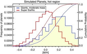
Luckily, the similarity in predictions of CA and Tidal Downsizing essentially ends with the ~ 1 Jupiter mass planets inside the inner few AU.
9.2. Sub-giant planets
Observations show that massive core-dominated planets are abundant at all metallicities (e.g., Mayor et al. Reference Mayor2011; Buchhave et al. Reference Buchhave2014; Buchhave & Latham Reference Buchhave and Latham2015), in contrast to the results for the gas giant planets. More qualitatively, the recent analysis of data by Wang & Fischer (Reference Wang and Fischer2015) shows that gas giants are ~ 9 times more likely to form around [M/H] > 0 hosts than they are around [M/H] < 0 hosts. For sub-Neptune planets, the ratio is only around 2.
The red histogram in Figure 18 shows the metallicity distribution from Nayakshin & Fletcher (Reference Nayakshin and Fletcher2015) of hosts of super-Earth planets defined here as planets with mass in the range 2M ⊕ < M p < 15M ⊕. This distribution is much more centrally peaked than it is for gas giants, in qualitative consistency with the observations. As already explained in Section 9.1, at low [M/H], most gas fragments migrating inward from their birth place at tens of AU are tidally disrupted. This would in fact yield an anti-correlation between the number of cores created per initial fragment and [M/H] of the star in the context of Tidal Downsizing. However, low metallicity gas fragments contain less massive cores on average (many of which are less massive than 2M ⊕). Thus, while there are more cores at low [M/H] environments, the more massive cores are found at higher metallicity. The net result is an absence of a clear correlation in Tidal Downsizing between the core-dominated planet and the metallicity of their hosts, unlike for gas giants.
This result is not due to cherry picking of parameters for population synthesis and is very robust at least qualitatively. Same physics—the fact that gas fragments are disrupted more frequently at low [M/H] environments—explains simultaneously why gas giants correlate and sub-giants do not correlate with metallicity.
A weak correlation of massive cores with [M/H] of the host star in CA was explained as following. Cores grow in gas-free environment in discs of low metallicity stars (e.g., Ida & Lin Reference Ida and Lin2004b; Mordasini et al. Reference Mordasini, Alibert, Benz and Naef2009b). These cores are then not converted into gas giants because they had no gas to accrete to make gas-dominated planets. However, this scenario does not tally well with the fact that many of close-in sub-giant planets reside in multi-planet systems, and these are by and large very flat (have mutual inclinations i ≲ 2°, see Fabrycky et al. Reference Fabrycky2014) and have low eccentricities (e ~ 0.03). Such systems are best explained by assembly via migration of planets (made at larger distances) in a gaseous protoplanetary disc which naturally damps eccentricities and inclinations away (Paardekooper, Rein, & Kley Reference Paardekooper, Rein and Kley2013; Hands, Alexander, & Dehnen Reference Hands, Alexander and Dehnen2014).
9.3. Gas giants beyond a few AU
The exclusion zone shown with the red line in the right panel of Figure 17 divides the Tidal Downsizing gas giant population in two. Inwards of the line, gas giants must have collapsed into the second cores before they entered this region. Since this is more likely at high metallicities of the host disc, there is a positive [M/H] correlation for the inner gas giants as explored in Section 9.1. Outside the exclusion zone, however, gas giants may remain in the pre-collapse configuration and still survive when the disc is dispersed. Thus, higher pebble accretion rates do not offer survival advantages at such relatively large distances from the star. This predicts that gas planets beyond the exclusion zone may not correlate with the metallicity of the host (see Figure 11 in Nayakshin & Fletcher Reference Nayakshin and Fletcher2015).
CA is likely to make an opposite prediction. Observations show that protoplanetary discs are dispersed almost equally quickly at small and large distances (see the review by Alexander et al. Reference Alexander, Pascucci, Andrews, Armitage, Cieza, Beuther, Klessen, Dullemond and Henning2014). Since classical core assembly takes longer at larger distances, one would expect gas giants at larger distances to require even higher metallicities to make a core in time before the gas disc goes away. Exact separation where this effect may show up may however be model dependent.
While statistics of gas giant planets at distances exceeding a few AU is far less complete than that for planets at a < 1 AU, Adibekyan et al. (Reference Adibekyan2013) reports that planets orbiting metal-rich stars tend to have longer periods than planets orbiting metal-rich stars (see Figure 20).
9.4. Very massive gas giants
As explained in Section 6.4, Tidal Downsizing makes a robust prediction for how planet-host metallicity correlation should change for more massive planets. For planets M p ≳ 5MJ, the radiative cooling time is comparable to 104 yrs, implying that fragments of such a mass may collapse before they reach the exclusion zone. High mass planets may therefore avoid tidal disruption simply by radiative cooling.
Accordingly, we should expect that high mass planets and BDs should be found with roughly equal frequency around metal-rich and metal-poor stars, in stark contrasts to Jupiter-mass planets. Figure 19, the top left panel, shows the host metallicity distribution for planets ending up at a < 15 AU in simulation ST from Nayakshin (Reference Nayakshin2015d). The figure shows two mass bins, 0.75MJ ⩽ M p ⩽ 3MJ (black) and M p ⩾ 5MJ (cyan). The red curve shows the initial (gaussian, centred on [M/H] = 0 and with dispersion σ = 0.22) distribution of host disc [M/H]. It is seen that moderately massive giants are shifted towards significantly higher metallicities, as previously found (Figure 18). In particular, only 20% of the planets in the black distribution have [M/H] < 0. Planets more massive than 5MJ are distributed more broadly, with 45% of the planets having negative [M/H].
Top: Theoretical predictions of population synthesis models. Left is distribution of gas giants over host star metallicity in two ranges of planet masses from population synthesis model of Nayakshin (Reference Nayakshin2016b). Black shows planets with mass 0.75MJ ⩽ M p ⩽ 3MJ, whereas the filled cyan histogram is for M p > 5MJ. Top right is Figure 4 from Mordasini et al. (Reference Mordasini, Alibert, Benz, Klahr and Henning2012), showing planet mass versus host metallicity in their simulations. Tidal Downsizing predicts that the more massive is the planet, the more likely it is to be metal poor; CA makes an opposite prediction (cf. Section 9.4). Bottom: Observations. Bottom left: Host metallicity distribution for gas giant planets from ‘exoplanets.org’, divided into two mass bins as in the panel above. Bottom right: Similar distribution but for sub-stellar mass companions from Troup et al (Reference Troup2016) with M psini > 0.013M⊙ (green) and the brown dwarf sub-sample (yellow; 0.013 < M psini < 0.08M⊙).

The CA model makes an opposite prediction. The inset in the top right panel of Figure 19 reproducesFootnote 6 Figure 4 from Mordasini et al. (Reference Mordasini, Alibert, Benz, Klahr and Henning2012), whereas the black and the cyan histograms show the host metallicity distribution for planets in the same mass ranges as for the top left panel. The blue histogram shows the metallicity distribution for BDs. It is easy to see from the figure that the more massive a gas giant planet is, the more metal rich the parent star should be to make that planet by CA. This result is probably quite robust since it relies on the key physics of the model. It takes a long time to make massive cores and planets in CA scenario (Pollack et al. Reference Pollack1996; Ida & Lin Reference Ida and Lin2004b). The more massive the planet is to be, the earlier it must start to accrete gas to arrive at its final mass or else the gas disc dissipates away. More metal-rich hosts make massive cores more rapidly, so most massive planets should be made in most metal-rich discs.
These predictions can be contrasted with the data. The bottom left panel of Figure 19 shows the observed metallicity distributions for hosts of gas giant planets that are currently on the ‘exoplanets.org’ database. Planets more massive than M p = 5MJ are shown with the filled cyan histogram, whereas the moderately massive giants correspond to the black histogram, selected by 0.75MJ ⩽ M p ⩽ 3MJ. The mass cut is the only selection criterion applied to the data. Both histograms are normalised on unit area. The massive group of planets is comprised of 96 objects and has a mean metallicity of − 0.014, whereas the less massive group is more populous, with 324 objects and the mean metallicity of 0.066.
While the statistics of exoplanetary data remains limited, we can see that the trend towards lower [M/H] hosts at higher M p is definitely present in the data. We can also confidently conclude that there is no shift towards higher [M/H] for the more massive planets. The bottom right panel of the figure shows [M/H] correlations for BD mass companions to stars from Troup et al. (Reference Troup2016) which are discussed in the next section.
No fine tuning was done to the population synthesis parameters to achieve this agreement. One physical caveat here is that gas accretion onto the planet is entirely neglected for both pre-collapse and post-collapse configurations. If some post-collapse fragments do accrete gas, then some of the massive planets, M p ≳ 5MJ, could have started off as less massive planets. These planets would then remain sensitive to the metallicity of the host. Therefore, if the observed massive M p > 5MJ planets are a mix of accreting and non-accreting populations, then there would remain some preference for these planets to reside in metal-rich systems, but this preference should be weaker than that for the moderately massive gas giants.
9.5. Close brown dwarf companions to stars
9.5.1. Are brown dwarfs related to planets?
It is often argued (e.g., Winn & Fabrycky Reference Winn and Fabrycky2015) that BDs and low mass stellar companions must form in a physically different way from that of planets because (a) the frequency of BD occurrence around Solar type stars is an order of magnitude lower than that for gas giant planets at periods less than a few years (e.g., Sahlmann et al. Reference Sahlmann2011; Santerne et al. Reference Santerne2016); (b) gas giant planets correlate strongly with metallicity of the host star, whereas for BDs the metallicity distribution is very broad with no evidence for a positive correlation (Raghavan et al. Reference Raghavan2010); (c) gas giant planets are over-abundant in metals compared to their host stars (Guillot Reference Guillot2005; Miller & Fortney Reference Miller and Fortney2011) whereas BDs have compositions consistent with that of their host stars (Leconte et al. Reference Leconte, Baraffe, Chabrier, Barman and Levrard2009).
These arguments are not water tight, however. The differences quoted above could be explainable in terms of a single scenario if predictions of that scenario are significantly different for objects of different masses. For example, gas giant planets are an order of magnitude less frequent than sub-giant planets, and their host metallicity correlations are significantly different (Mayor et al. Reference Mayor2011; Howard et al. Reference Howard2012), yet there is no suggestion that these two populations are not related. Both CA (Mordasini et al. Reference Mordasini, Alibert, Benz and Naef2009b) and Tidal Downsizing (Nayakshin & Fletcher Reference Nayakshin and Fletcher2015) may be able to explain the sub-Neptune mass planets and gas giants in a single unifying framework.
To be more specific with regard to a Tidal Downsizing origin of close-in BDs, these objects may be hatched less frequently than gas giants via gravitational instability of the disc. Alternatively, BDs may be migrating into the inner few au disc from their birth place less efficiently than gas giants do (the migration rate in the type II regime is inversely proportional to the object mass, see, e.g., Lodato & Clarke Reference Lodato and Clarke2004).
A trademark of two completely different formation scenarios would be a clean break (discontinuity) between gas giants and BDs in any of the above observational characteristics. There does not appear to be an observational evidence for such a break. The occurrence rate of gas giants drops with planet mass towards the BD regime monotonically (e.g., Figure 13 in Cumming et al. Reference Cumming2008); the host metallicity correlation of very massive gas giants becomes weak towards masses of ~ 10MJ, before hitting the BD regime, as discussed in Section 9.4; and the metallicity of gas giants also continuously drops with M p increasing towards BDs (e.g., Miller & Fortney Reference Miller and Fortney2011, and also Section 10.1 and Figure 21 below).
Based on the continuity of the transition in all of these properties, it is therefore possible to consider gas giant planets and BD as one continuous population that forms in the same way. Reggiani et al. (Reference Reggiani2016) argue that the observed companion mass function at wide orbits around solar-type stars can be understood by considering giant planets and BDs a part of the same population as long as a cut-off in planet separation distribution is introduced around ~ 100 AU.
A physically similar origin for planets and brown dwarfs is allowed by both planet formation scenarios. In Tidal Downsizing, brown dwarfs were either born big or managed to gain more gas. In CA, brown dwarfs are over-achieving gas giant planets (Mordasini et al. Reference Mordasini, Alibert, Benz, Klahr and Henning2012).
9.5.2. Metallicity correlations of brown dwarfs
If planets and brown dwarfs are a continuous population, then it appears that data favour Tidal Downsizing over CA as a formation route for these objects.
Raghavan et al. (Reference Raghavan2010) showed that brown dwarf companions to solar mass stars are very broadly distributed over host [M/H]. For low mass stellar companions, it is the low metallicity hosts that are more likely to host the companion. Very recent observations of Troup et al. (Reference Troup2016) detail the picture further. These authors presented a sample of 382 close-in stellar and sub-stellar companions, about a quarter of which are brown dwarfs at separations between ~ 0.1 to ~ 1 AU. Out of these brown dwarfs, 14 have [M/H] < −0.5. To put this in perspective, out of many hundreds of planets with mass 0.5MJ < M p < 5MJ on ‘exoplanets.org’ (Han et al. Reference Han2014), only four have [M/H] < −0.5.
The bottom right panel of Figure 19 shows the host star metallicity distribution for brown dwarfs (yellow) and for all companions more massive than 0.013M⊙ (green) from the Troup et al. (Reference Troup2016) data. As authors note, their observations strongly challenge CA model as an origin for the brown dwarfs in their sample.
Indeed, Mordasini et al. (Reference Mordasini, Alibert, Benz, Klahr and Henning2012) in their Section 4.3 state: ‘While we have indicated in Section 4.1 that metallicity does not significantly change the distribution of the mass for the bulk of the population, we see here that the metallicity determines the maximum mass a planet can grow to in a given disk, in particular for subsolar metallicities. There is an absence of very massive planets around low-metallicity stars’. To emphasise the point, the authors look at the maximum planet mass in their models at metallicity [M/H] < −0.4. For their nominal model, the resulting maximum planet mass of the low [M/H] tail of the population is only 7MJ. This is at odds with the observations (Raghavan et al. Reference Raghavan2010; Troup et al. Reference Troup2016).
9.6. Debris discs
There is another checkpoint we can use to compare theoretical models of host metallicity correlations with observations: the debris discs (Wyatt Reference Wyatt2008).
Detailed calculations of planetesimal formation (e.g., Johansen et al. Reference Johansen2007, Reference Johansen, Youdin and Mac Low2009), suggest that planetesimal formation efficiency is a strong function of metallicity of the parent disc. It is therefore assumed that higher [M/H] discs have more abundant supply of planetesimals. This is in fact required if CA is to explain the positive gas giant correlation with the host star metallicity (e.g., Ida & Lin Reference Ida and Lin2004b; Mordasini et al. Reference Mordasini, Alibert, Benz and Naef2009b).
As detailed in Section 5.3, Tidal Downsizing scenario offers a different perspective on formation of minor solid bodies. The very central parts of the self-gravitating gas fragments may be producing solid bodies greater than a few km in size by self-gravitational collapse mediated by gas drag (Section 7.3). Observable planetesimals are however created only when the parent gas fragment is disrupted; in the opposite case, the planetesimal material is locked inside the collapsed gas giant planet.
Debris discs are detected around nearby stars (Wyatt Reference Wyatt2008) via thermal grain emission in the infra-red (Oudmaijer et al. Reference Oudmaijer1992; Mannings & Barlow Reference Mannings and Barlow1998). Interestingly, debris discs detection frequency does not correlate with [M/H] of their host stars (Maldonado et al. Reference Maldonado, Eiroa, Villaver, Montesinos and Mora2012; Marshall et al. Reference Marshall2014; Moro-Martín et al. Reference Moro-Martín2015). Observed debris discs also do not correlate with the presence of gas giants (e.g., Moro-Martín et al. Reference Moro-Martín2007; Bryden et al. Reference Bryden2009; Kóspál et al. Reference Kóspál, Ardila, Moór and Ábrahám2009). It is not that debris discs do ‘not know’ about planets: Stars with an observed gas giant are half as likely to host a detected debris discs than stars orbited by planets less massive than $30 \text{M}_\oplus$
(Moro-Martín et al. Reference Moro-Martín2015).
$30 \text{M}_\oplus$
(Moro-Martín et al. Reference Moro-Martín2015).
The suggestion that debris discs are destroyed by interactions with gas giants (Raymond et al. Reference Raymond2011) could potentially explain why debris discs do not correlate with [M/H] or gas giant presence. However, the observed gas giants (for which the correlations were sought) are orbiting their hosts at separations ≲ 1 AU, whereas the observed debris discs can be as large as tens and even hundreds of AU, making their dynamical interaction (in the context of CA) unlikely. Further, radial velocity, microlensing, and direct imaging results all show that there is of order ~ 0.1 gas giant planets per star (Santerne et al. Reference Santerne2016; Shvartzvald et al. Reference Shvartzvald2016; Biller et al. Reference Biller2013; Bowler et al. Reference Bowler, Liu, Shkolnik and Tamura2015; Wittenmyer et al. Reference Wittenmyer2016) at both small and large separations from the host star, whereas Raymond et al. (Reference Raymond2011)’s scenario needs several giants in a debris disc-containing system to work.
In Tidal Downsizing, higher [M/H] discs provide higher pebble accretion rates, so that few gas fragments are destroyed. Debris disc formation is hence infrequent at high metallicities compared to low [M/H] hosts. However, each disrupted fragment contains more metals in higher [M/H] than their analogues in low metallicity systems.
Fletcher & Nayakshin (Reference Fletcher and Nayakshin2016) found that the debris disc—host metallicity correlation from Tidal Downsizing would depend on the sensitivity of synthetic survey. A high sensitivity survey picks up low [M/H] hosts of debris discs most frequently because they are more frequent. So such surveys would find an anti-correlation between debris disc of presence and host metallicity. A medium sensitivity surveys however would find no correlation, and a low sensitivity surveys shows preference for debris around high metallicity hosts. These results appear qualitatively consistent with observations of debris disc—host star metallicity correlation.
Fletcher & Nayakshin (Reference Fletcher and Nayakshin2016) also considered planet—debris discs correlations in Tidal Downsizing. A detected gas giant planet implies that the parent fragment did not go through a tidal disruption—hence not producing a debris disc at all. A detected sub-Saturn mass planet, on the other hand, means that there was an instance of debris disc formation. In a single migrating fragment scenario, that is when there is only one fragment produced by the parent disc, this would imply that gas giants and debris discs are mutually exclusive, but sub-Saturn planets and debris discs are uniquely linked. However, in a multi-fragment scenario, which is far more realistic based on numerical simulations of self-gravitating discs (Section 4), other fragments could undergo tidal disruptions and leave debris behind. Survival of a detectable debris disc to the present day also depends on where the disruption occurred, and the debris discs—migrating gas fragment interactions, which are much more likely in Tidal Downsizing scenario than in CA because pre-collapse gas giants are widespread in Tidal Downsizing and traverse distances from ~ 100 AU to the host star surface. Therefore, we expect a significant wash-out of the single fragment picture, but some anti-correlation between debris discs and gas giants and the correlation between debris discs and sub-giants may remain.
9.7. Cores closest to their hosts
Adibekyan et al. (Reference Adibekyan2013) shows that planets around low metallicity hosts tend to have larger orbits than their metal-rich analogues. The trend is found for all planet masses where there is sufficient data, from ~ 10M ⊕ to 4MJ. Their Figure 1, right panel, reproduced here in Figure 20, shows this very striking result. The dividing metallicity for the metal-poor versus metal-rich hosts was set at [M/H] = −0.1 in the figure. The figure was modified (see below) with permission. The blue crosses show metal-rich systems whereas the red circles show metal-poor systems. Adibekyan et al. (Reference Adibekyan, Figueira and Santos2016) extended this result to lower mass/radius cores, showing that metal-rich systems of cores tend to be more compact than systems of planets around metal-poor stars (see the bottom panels in their Figure 1).
The right panel of Figure 1 from Adibekyan et al. (Reference Adibekyan2013), showing the planet period versus its mass. The sample is separated into the metal-poor and metal-rich sub-samples. The green, blue, and red lines are added on the plot with permission from the authors. The green line is the exclusion zone boundary [equation (3)], which shows approximately how far a pre-collapse gas fragment of mass M p can approach an M * = 1M⊙ star without being tidally disrupted. The blue and red lines contrast how gas fragments evolve in a metal-rich and a metal-poor disc, respectively. See text in Section 9.7 for more detail.

As noted by Adibekyan et al. (Reference Adibekyan2013), in the CA context, massive cores in metal-poor discs are expected to appear later than they do in metal-rich ones. At these later times, the protoplanetary discs may be less massive on average. Cores formed in metal-poor systems should therefore migrate slower [cf. equation (7)]. They also have less time before their parent gas discs are dissipated. Hence, one may expect that cores made in metal-deficient environments migrate inward less than similar cores in metal-rich environment.
However, planet masses span a range of ~ 1000 in Figure 20. This means that planet migration rates may vary by a similar factor—from some being much longer than the disc lifetime, and for the others being as short as ~ 104 yrs. It is therefore not clear how a difference in timing of the birth of the core by a factor of a few would leave any significant imprint in the final distribution of planets across such a broad planet mass range.
In Tidal Downsizing, there is no significant offset in when the cores are born in metal-rich or metal-poor discs. All cores are born very early on. However, as described in Section 6.3 and 9.1, gas fragments in metal-poor discs tend to be disrupted by stellar tides when they migrate to separations of a few AU. This forms an exclusion zone barrier (cf. the red line in the right panel of Figure 17 and the green line in Figure 20), so that, as already explained (Section 9.3), moderately massive gas giants around metal-poor hosts are to be found mainly above the green line in Figure 20. Fragments in metal-rich systems, however, are more likely to contract and collapse due to pebble accretion before they reach the exclusion zone, so they can continue to migrate into the sub-AU regions. The exclusion zone hence forms a host metallicity dependent filter, letting gas giants pass in metal-rich systems but destroying them in metal-poor ones.
Further, as explained in Section 9.4, planets more massive than ~ 5MJ cool rapidly radiatively, and thus they are able to collapse and pass the barrier without accreting pebbles. These high M p planets are not expected to correlate wth [M/H] strongly at any separation (Section 9.4). This is consistent with Figure 20—note that a larger fraction of gas giants are metal rich at high planet masses.
Let us now consider what happens with M p ~ 1MJ fragments after they reach the exclusion zone in some more detail. The blue lines with arrows show what may happen to such a planet in the metal-rich case. Since the planet is in the second, dense configuration, it may continue to migrate in as long as the gas disc is massive enough. The fragments will eventually enter the hot Jupiter regime (periods P ≲ 10 d). Some just remain there when the gas disc dissipates; others are pushed all the way into the star. Yet, others can be disrupted at about a ~ 0.1 AU by a combination of over-heating because of the very hot disc environment and disruption by stellar tides (this was called the ‘second disruption’ in Section 6.5). The disrupted fragments then travel approximately horizontally in the diagram, as indicated by the blue horizontal arrow, becoming hot sub-Saturn or hot super Earth planets (Nayakshin Reference Nayakshin2011b).
In contrast, tidal disruption of gas fragments in metal-poor systems occurs at around the exclusion zone boundary. The planet also travels horizontally to lower planet mass regime, as shown with the horizontal red line in Figure 20. After the disruption, these low mass planets (usually dominated by massive cores), continue to migrate inward, now evolving vertically downward as shown in Figure 20 with the vertical red line. Planet migration rate in type I regime is relatively slow for core-dominated planets, thus one can then expect that the ‘red cores’ will in general not migrate as far in as did the ‘blue ones’.
Focussing on the lowest mass cores, M
core ⩽ 0.03MJ ~ 10M
⊕ in Figure 20, we note quite clearly a dearth of metal-rich (blue crosses) cores beyond the period of ${\sim }10\text{--}20$
d, which corresponds to
${\sim }10\text{--}20$
d, which corresponds to $a \approx 0.1\text{--}0.15$
AU. In principle, this could be a detectability threshold effect—planets are progressively more difficult to detect at longer periods. However, the approximate (empirical) detection threshold is shown in the figure with the dotted line, which is a factor of several longer than the 10-dperiod; so these observational results are unlikely to be due to detection biases.
$a \approx 0.1\text{--}0.15$
AU. In principle, this could be a detectability threshold effect—planets are progressively more difficult to detect at longer periods. However, the approximate (empirical) detection threshold is shown in the figure with the dotted line, which is a factor of several longer than the 10-dperiod; so these observational results are unlikely to be due to detection biases.
Second disruptions have not yet been included in rigorous enough detail in the population synthesis.
10 PLANET COMPOSITIONS
10.1. Metal over-abundance in gas giants
Heavy element content of a giant planet can be found with some certainty by knowing just the planet mass and radius (Guillot Reference Guillot2005), provided it is not too strongly illuminated (Miller & Fortney Reference Miller and Fortney2011; Thorngren et al. Reference Thorngren, Fortney and Lopez2016). Heavy elements contribute to the total mass of the planet, but provide much less pressure support per unit weight.
Metal over-abundance of gas giant planets is expected in Tidal Downsizing thanks to partial stripping of outer metal-poor layers (Nayakshin Reference Nayakshin2010a) and pebble accretion. In Nayakshin (Reference Nayakshin2015a), it was estimated that accreted pebbles need to account for at least ~ 10% of planet mass for it to collapse via pebble accretion as opposed to the radiative channel. This number however depends on the mass of the fragment. As explained in Sections 6.4 9.4, more massive gas giants cool more rapidly at the same dust opacity. For this reason, they are predicted to not correlate as strongly with the host star metallicity (see Section 9.4) and require less pebbles to accrete in order to collapse.
Figure 21 shows the relative over-abundance of gas giant planets, that is, the ratio Z pl to star metal content, Z *, as a function of the planet mass from population synthesis by Nayakshin & Fletcher (Reference Nayakshin and Fletcher2015) compared with the results of Miller & Fortney (Reference Miller and Fortney2011), who deduced metal content for a number of exoplanets using observations and their planet evolution code. No parameter of the population synthesis was adjusted to reproduce the Miller & Fortney (Reference Miller and Fortney2011) results.
Metal over-abundance of gas giant planets versus their mass. Blue squares with error bars shows the results of Miller & Fortney (Reference Miller and Fortney2011). The other symbols are results from population synthesis, binned into four host star metallicity bins as detailed in the legend.
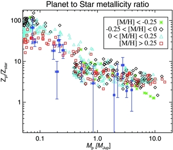
Figure 21 also shows that there is a continuous metallicity trend with M p from ~ 0.1MJ all the way into the BD regime. The continuous transition in metal over-abundance from gas giants to BDs argues that BD formation may be linked to formation of planets (Section 9.5.1).
10.2. Core compositions
Tidal Downsizing predicts rock-dominated composition for cores (Nayakshin & Fletcher Reference Nayakshin and Fletcher2015, and Section 7.4). CA scenario suggests that massive core formation is enhanced beyond the snow line since the fraction of protoplanetary disc mass in condensible solids increases there by a factor of up to ~ 3 (e.g., see Table I in Pollack et al. Reference Pollack1996). Most massive cores are hence likely to contain a lot of ice in the CA model. Reflecting this, Neptune and Uranus in the SS are often referred to as ‘icy giants’ even though there is no direct observational support for their cores actually being composed of ice (see Section 5.1.2 in Helled et al. Reference Helled, Beuther, Klessen, Dullemond and Henning2014). For example, for Uranus, the gravity and rotation data can be fit with models containing rock or ice as condensible material (Helled, Anderson, & Schubert Reference Helled, Anderson and Schubert2010). When SiO2 is used to represent the rocks, Uranus interior is found to consist of 18% hydrogen, 6% helium, and 76% rock. Alternatively, when H2O is used, Uranus composition is found to be 8.5% and 3% of H and He, respectively, and 88.5% of ice.
Composition of extrasolar cores is obviously even harder to determine. Rogers (Reference Rogers2015) shows that most Kepler planets with periods shorter than 50 d are not rocky for planet radii greater than 1.6R ⊕ as their density is lower than an Earth-like core would have at this size. Unfortunately, just like for the outer giants in the SS, the interpretation of this result is degenerate. It could be that these planets contain icy cores instead of rocky ones, but it is also possible that the data can be fit by rocky cores with small atmospheres of volatiles on top.
To avoid these uncertainties, we should focus on cores that are unlikely to have any atmospheres. Close-in (a ≲ 0.1 AU) moderately massive cores (M core ≲ 7M ⊕, see Owen & Wu Reference Owen and Wu2013) are expected to lose their atmosphere due to photo-evaporation. The observed close-in planets in this mass range all appear to be very dense, requiring Venus/Earth rock-dominated compositions (e.g., Figure 4 in Dressing et al. Reference Dressing2015). Espinoza et al. (Reference Espinoza2016) present observations of a Neptune mass planet of radius R p ≈ 2.2R ⊕, making it the most massive planet with composition that is most consistent with pure rock. Weiss et al. (Reference Weiss2016) re-analyse the densities of planets in the Kepler-10 system and find that planet c has mass of ≈ 14M ⊕ and its composition is consistent with either rock/Fe plus 0.2% hydrogen envelope by mass or Fe/rock plus (only) 28% water. There thus appears to be no evidence so far for ice-dominated massive cores in exoplanetary systems.
Another interesting way to probe the role of different elements in making planets is to look at the abundance difference between stars with and without planets. Observations show little difference in differential element abundances between ‘twin stars’ except for refractory elements (Maldonado & Villaver Reference Maldonado and Villaver2016), again suggesting that ices are not a major planet building material, whereas silicates could be. These results may be disputed, however, because the effects of Galactic stellar evolution (González Hernández et al. Reference González Hernández2013) drive extra variations in abundance of metals. These effects are hard to deconvolve from the possible planet/debris disc formation signatures.
Cleaner although very rare laboratories are the nearly identical twin binaries, which certainly suffer identical Galactic influences. Saffe et al. (Reference Saffe, Flores, Jaque Arancibia, Buccino and Jofre2016) studies the ζ Ret binary which contains nearly identical stars separated by ~ 4000 AU in projection. One of the twins has a resolved debris disc of size ~ 100 AU (Eiroa et al. Reference Eiroa2010), whereas the other star has no planet or debris disc signatures. Refractory elements in the debris disc hosting star are deficient (Saffe et al. Reference Saffe, Flores, Jaque Arancibia, Buccino and Jofre2016) compared to its twin by at least 3M ⊕, which the authors suggest is comparable to the mass of solids expected to be present in a debris disc of this spatial size. Results of Saffe et al. (Reference Saffe, Flores, Jaque Arancibia, Buccino and Jofre2016) are therefore consistent with that of Maldonado & Villaver (Reference Maldonado and Villaver2016) and could not be driven by the Galactic chemical evolution. This twin binary observation is especially significant since the debris disc size is ~ 100 AU, well beyond a snow line, so ices should be easily condensible into planets/debris. If ices were the dominant reservoir from which debris discs and planets are made, then they should be missing in the star with the observed debris.
11 PLANET MASS FUNCTION
11.1. Mass function
Small planets, with radius less than that of Neptune ( ~ 4R
⊕) are ubiquitous (Howard et al. Reference Howard2012). This planet size translates very roughly to mass of ~ 20M
⊕ (Dressing et al. Reference Dressing2015). Observations of close-in exoplanets show that PMF plummets above this size/mass (Howard et al. Reference Howard2012; Mayor et al. Reference Mayor2011). These observations add to the long held belief, based on the SS planets’ observations, that the planetary cores of mass $M_{\rm core}\sim 10\text{--}20 {\,{\it M}_{\oplus }}$
have a very special role to play in planet formation.
$M_{\rm core}\sim 10\text{--}20 {\,{\it M}_{\oplus }}$
have a very special role to play in planet formation.
In the CA scenario, this special role is in building gas giant planets by accretion of protoplanetary disc gas onto the cores (Mizuno Reference Mizuno1980; Papaloizou & Terquem Reference Papaloizou and Terquem1999; Rafikov Reference Rafikov2006). In Tidal Downsizing, the role of massive cores in building gas giant planets is negative due to the feedback that the core releases (Section 7.5). The observed dearth of gas giants and abundance of small planets means in the context of Tidal Downsizing that most of the gas fragments originally created in the outer disc must be disrupted or consumed by the star to be consistent with the data.
The top panel of Figure 22 shows the observed PMF from Mayor et al. (Reference Mayor2011). The black shows the actual number of planets, whereas the red shows the PMF corrected for observational bias. The bottom panel of Figure 22 shows PMF from three population synthesis calculations performed with three contrasting assumptions about the physics of the cores (Nayakshin Reference Nayakshin2016b) in the model, to emphasise the importance of core feedback in Tidal Downsizing. Simulation ST (standard) includes core feedback, and is shown with the blue histogram. This PMF is reasonably similar to the observed one in the top panel.
Top panel: Planet mass function (PMF) from HARPS spectrograph observations from Mayor et al. (Reference Mayor2011). The black histogram gives observed number of planets, whereas the red corrects for observational bias against less massive planets. Bottom panel: PMF from the Tidal Downsizing population synthesis calculations, exploring the role of core feedback. The histograms are for runs without core formation (NC), with core formation but feedback off (DC) and standard (ST), which includes core feedback. Without feedback, the PMF of Tidal Downsizing scenario looks nothing like the observed mass function.

In simulation NC (no cores), shown with the yellow histogram, core formation is artificially turned off. In this case, tidal disruptions of gas fragments leave behind no cores. Thus, only gas giant planets are formed in this simulation. In simulation DC (dim cores), shown with the red histogram in the bottom panel, core formation is allowed but the core luminosity is arbitrarily reduced by a factor of 105 compared with simulation ST.
By comparing simulations ST and DC, we see that the core luminosity is absolutely crucial in controlling the kind of planets assembled by the Tidal Downsizing scenario. A strong core feedback leads to a much more frequent gas fragment disruption, reducing the number of survived gas fragments at all separations, small or large. This also establishes the maximum core mass [ $10\text{--}20{\,{\it M}_{\oplus }}$
, equation (25) and Section 7.5], above which the cores do not grow because the parent clumps cannot survive so much feedback.
$10\text{--}20{\,{\it M}_{\oplus }}$
, equation (25) and Section 7.5], above which the cores do not grow because the parent clumps cannot survive so much feedback.
In simulation DC (dim cores), cores grow unconstrained by their feedback and so they become much more massive (see also Figure 5 in Nayakshin Reference Nayakshin2016b, on this) than in simulation ST, with most exceeding the mass of 10M ⊕. Given that they are also dim, these cores are always covered by a massive gas atmosphere even when the gas fragment is disrupted (cf. the next section). This is why there are no ‘naked cores’ in simulation DC.
One potentially testable prediction is this. As core mass approaches ~ 10M
⊕, feedback by the core puffs up the fragment and thus $\text{d}M_{\rm core}/\text{d}t$
actually drops. Therefore, growing cores spend more time in the vicinity of this mass. Since core growth is eventually terminated by the fragment disruption or by the second collapse, whichever is sooner, the mass of cores should cluster around this characteristic mass. In other words, the core mass function should show a peak at around ~ 10M
⊕ before it nose-dives at higher masses.
$\text{d}M_{\rm core}/\text{d}t$
actually drops. Therefore, growing cores spend more time in the vicinity of this mass. Since core growth is eventually terminated by the fragment disruption or by the second collapse, whichever is sooner, the mass of cores should cluster around this characteristic mass. In other words, the core mass function should show a peak at around ~ 10M
⊕ before it nose-dives at higher masses.
There may be some tentative evidence for this from the data. Silburt, Gaidos, & Wu (Reference Silburt, Gaidos and Wu2015) looked at the entire Kepler sample of small planets over all 16 quarters of data, and built probably the most detailed to date planet radius function at R p ⩽ 4R ⊕. They find that there is in fact a peak in the planet radius distribution function at R p ≈ 2.5R ⊕, which corresponds to M core ≈ 15M ⊕.
11.2. Atmospheres of cores: the bimodality of planets
One of the most famous results of CA theory is the critical mass of the core, M crit ~ a few to ~ 10–20M ⊕, at which it starts accreting gas from the protoplanetary disc (Mizuno Reference Mizuno1980; Stevenson Reference Stevenson1982; Ikoma et al. Reference Ikoma, Nakazawa and Emori2000; Rafikov Reference Rafikov2006; Hori & Ikoma Reference Hori and Ikoma2011). For core masses less than M crit, the cores are surrounded by usually tiny atmospheres.
In Section 7.6, it was shown that a massive core forming inside a self-gravitating gas fragment in the context of Tidal Downsizing also surrounds itself by a dense gas atmosphere for exactly same reasons, except that the origin of the gas is not the surrounding protoplanetary disc but the parent fragment. Nayakshin et al. (Reference Nayakshin, Helled and Boley2014) calculated the atmosphere structure for a given central properties of the gas fragment (gas density, temperature, composition), core mass, and luminosity. The population synthesis model of Nayakshin (Reference Nayakshin2015c); Nayakshin & Fletcher (Reference Nayakshin and Fletcher2015) uses the same procedure with a small modification. To determine the mass of the atmosphere actually bound to the core, I consider the total energy of atmosphere shells. Only the innermost layers with a negative total energy are considered bound to the core. These layers are assumed to survive tidal disruption of the fragment.
Figure 23 is reproduced from Nayakshin & Fletcher (Reference Nayakshin and Fletcher2015), and shows the mass of all of the cores in the inner 5 AU from the host at the end of the simulations (green shaded), while the red histogram shows the mass distribution of gas in the same planets. Gas fragments that were not disrupted remain in the Jovian mass domain, within the bump at log(M gas/M ⊕) > 2. These planets are dominated by the gas but do have cores. The second, much more populous peak in the red histogram in Figure 23 is at tiny, ~ 10−3 M ⊕ masses. This peak corresponds to the gas fragments that were disrupted and became a few Earth mass cores with the small atmospheres.
The distribution of core and gas masses for planets in the inner 5 AU from population synthesis calculations of Nayakshin & Fletcher (Reference Nayakshin and Fletcher2015). Note that the planets are either core-dominated with tiny atmospheres or gas giants. See Section 11.2 for more detail.
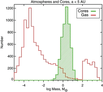
Tidal Downsizing scenario thus also naturally reproduces the observed bi-modality of planets—planets are either dominated by cores with low mass (up to ~ 10% of core mass, generally) atmospheres, or are totally swamped by the gas. The conclusion following from this is that the special role of ~ 10M ⊕ cores in planet formation may dependent on how the planets are made only weakly. It is likely that the ability of massive (M core ≳ 10M ⊕) cores to attract gas atmospheres of comparable mass is a fundamental property of matter (hydrogen equation of state, opacities) and does not tell us much about the formation route of these planets, at least not without more model-dependent analysis.
12 DISTRIBUTION OF PLANETS IN THE SEPARATION SPACE
12.1. Period Valley of gas giants
The radial distribution of gas giant planets has a ‘period valley’ at 0.1 < a < 1 AU (Cumming et al. Reference Cumming2008), which was interpreted as a signature of protoplanetary disc dispersal by Alexander & Pascucci (Reference Alexander and Pascucci2012). In their model, photo-evaporation removes disc gas most effectively from radii of ${\sim }1\text{--}2$
AU for a Solar type star, hence creating there a dip in the surface density profile. Therefore, planets migrating from the outer disc into the sub-AU region may stall at
${\sim }1\text{--}2$
AU for a Solar type star, hence creating there a dip in the surface density profile. Therefore, planets migrating from the outer disc into the sub-AU region may stall at $a\sim 1\text{--}2$
AU and thus pile up there.
$a\sim 1\text{--}2$
AU and thus pile up there.
The period valley issue has not yet been studied in Tidal Downsizing, but preliminary conclusions are possible. The photo-evaporation driven process of stalling gas giant planets behind ~ 1 AU should operate for both planet formation scenarios because it has to do with the disc physics. However, the timing of gas giant planet formation is different in the two models. CA planets are born late in the disc life, when the disc has lost most of its mass through accretion onto the star. Tidal Downsizing fragments are hatched much earlier, when the disc is more massive. Most of Tidal Downsizing fragments hence migrate through the disc early on, well before the photo-evaporative mass loss becomes important for the disc. During these early phases, the disc surface density profile does not have a noticeable depression at ${\sim }1\text{--}2$
AU (see Alexander & Pascucci Reference Alexander and Pascucci2012). Therefore, the photo-evaporative gap is probably not as efficient at imprinting itself onto the gas giant period or separation distribution in Tidal Downsizing as it is in the CA.
${\sim }1\text{--}2$
AU (see Alexander & Pascucci Reference Alexander and Pascucci2012). Therefore, the photo-evaporative gap is probably not as efficient at imprinting itself onto the gas giant period or separation distribution in Tidal Downsizing as it is in the CA.
However, the exclusion zone boundary at ~ 1 to a few AU is a hot metallicity-dependent filter for the gas giant planets (Section 9.1 & 9.7). Current population synthesis calculations in the Tidal Downsizing scenario show that the surface density of planets decreases somewhat at ~ 1 AU for all masses M p ≳ 1MJ (cf. Figure 17), and this effect is dominated by the tidal disruptions. The period valley should thus be stronger for metal-poor hosts than for metal-rich ones in Tidal Downsizing scenario.
12.2. On the rarity of wide separation gas giants
Although there are some very well-known examples of giant planets orbiting Solar type stars at separations of tens to ~ 100 AU, statistically there is a strong lack of gas giant planets observed at wide separations (e.g., Vigan et al. Reference Vigan2012; Chauvin et al. Reference Chauvin2015; Bowler et al. Reference Bowler, Liu, Shkolnik and Tamura2015). For example, Biller et al. (Reference Biller2013), finds that no more than a few % of stars host $1\text{--}20{\,{\rm M}_{\rm J}}$
companions with separations in the range
$1\text{--}20{\,{\rm M}_{\rm J}}$
companions with separations in the range $10\text{--}150$
AU. Galicher et al. (Reference Galicher2016) makes the most definitive statement, finding that the fraction of gas giants beyond 10 AU is ≈ 1%.
$10\text{--}150$
AU. Galicher et al. (Reference Galicher2016) makes the most definitive statement, finding that the fraction of gas giants beyond 10 AU is ≈ 1%.
Current population synthesis models (e.g., Nayakshin Reference Nayakshin2016b) exceed these constraints by a factor of a few to 10. This may be due to (a) the models assuming migration rates slower than the 3D simulations find (Section 4.2), so that more population synthesis planets remain at wide separations after the disc is removed; (b) neglect of gas accretion onto the planets which could take some of them into the BD regime (Sections 4.3 and 4.4); (c) too rapid removal of the outer disc in the models. These issues must be investigated in the future with both 3D simulations and population synthesis.
13 The HL Tau challenge
HL Tau is a young ( ${\sim }0.5\text{--}2$
Myr old) protostar that remains invisible in the optical due to obscuration on the line of sight, but is one of the brightest protoplanetary discs in terms of its millimetre radio emission (Andrews & Williams Reference Andrews and Williams2005; Kwon et al. Reference Kwon, Looney and Mundy2011). For this reason, Atacama Large Millimetre/Submillimetre Array (ALMA) observed HL Tau as one of the first targets, in the science verification phase, with baseline as long as 15 km (Brogan et al. Reference Brogan2015). This yielded resolution as small as 3.5 AU at the distance for the source, and resulted in the first ever image of a planet forming disc. The image of HL Tau shows a number of circular dark and bright rings in the dust emissivity of the disc. Such rings can be opened by embedded massive planets (e.g., Lin & Papaloizou Reference Lin and Papaloizou1986; Rice et al. Reference Rice, Armitage, Wood and Lodato2006; Crida et al. Reference Crida, Morbidelli and Masset2006).
${\sim }0.5\text{--}2$
Myr old) protostar that remains invisible in the optical due to obscuration on the line of sight, but is one of the brightest protoplanetary discs in terms of its millimetre radio emission (Andrews & Williams Reference Andrews and Williams2005; Kwon et al. Reference Kwon, Looney and Mundy2011). For this reason, Atacama Large Millimetre/Submillimetre Array (ALMA) observed HL Tau as one of the first targets, in the science verification phase, with baseline as long as 15 km (Brogan et al. Reference Brogan2015). This yielded resolution as small as 3.5 AU at the distance for the source, and resulted in the first ever image of a planet forming disc. The image of HL Tau shows a number of circular dark and bright rings in the dust emissivity of the disc. Such rings can be opened by embedded massive planets (e.g., Lin & Papaloizou Reference Lin and Papaloizou1986; Rice et al. Reference Rice, Armitage, Wood and Lodato2006; Crida et al. Reference Crida, Morbidelli and Masset2006).
Note that it is the dust emission that observable in the radio continuum, the gas of the disc can only be traced by its CO and HCO+ line emission. Pinte et al. (Reference Pinte2016) performed a detailed modelling of the dust component in HL Tau disc assuming circular orbits for the gas. The well-defined circular gaps observed at all azimuthal angles (HL Tau disc is inclined to the line of sight) imply that ~ millimetre sized dust has settled in a geometrically thin, H dust/R ~ 0.02, disc. This is much thinner than the gas disc which has H/R ~ 0.1 at these radii. The strong degree of grain settling sets an upper limit on the viscosity coefficient of the disc, requiring α ~ 3 × 10⁻⁴. The observed CO and HCO+ line profiles constrain the protostar mass, M * = 1.7M⊙. Pinte et al. (Reference Pinte2016) find hotter gas disc than Zhang, Blake, & Bergin (Reference Zhang, Blake and Bergin2015), who argued that the observed rings are formed by grain condensation at ice lines of abundant molecular species, and therefore their condensation fronts do not coincide with the gaps’ positions. The small but non-zero eccentricity of the rings, the surprisingly small magnitude of disc viscosity, coupled with irregular spacings of the rings, probably rule out Rossby wave instabilities or zonal flows (Pinilla et al. Reference Pinilla2012) as possible origins of the rings, leaving planets as the most likely origin of the gaps (Brogan et al. Reference Brogan2015).
A number of authors performed detailed coupled gas-dust hydrodynamical simulations to try to determine the properties of planets that are able to open gaps similar to those observed in HL Tau (Dipierro et al. Reference Dipierro2016b; Jin et al. Reference Jin, Li, Isella, Li and Ji2016; Picogna & Kley Reference Picogna and Kley2015; Dipierro et al. Reference Dipierro, Laibe, Price and Lodato2016a; Rosotti et al. Reference Rosotti, Juhasz, Booth and Clarke2016). The main conclusion from this work is that the minimum planet mass to produce the observed signatures is ~ 15M ⊕, while the maximum appears to be around 0.5MJ. Dipierro et al. (Reference Dipierro, Laibe, Price and Lodato2016a) find that the best match to the data is provided by planets of mass M p ≈ 20M ⊕, 30M ⊕, and 0.5MJ orbiting the star at orbits with semi-major axes of a ≈ 13, 32, and 69 AU, respectively.
These results challenge classical ideas of planet formation. It should take ~ 100 Myr to grow massive cores at tens of AU distances from the star via planetesimal accretion (e.g., Kobayashi et al. Reference Kobayashi, Tanaka and Krivov2011; Kenyon & Bromley Reference Kenyon and Bromley2015). The presence of massive cores in a ~ 1 Myr old disc at ~ 70 AU is unexpected and also contradicts the metallicity correlations scenario presented by Ida & Lin (Reference Ida and Lin2004a), Ida & Lin (Reference Ida and Lin2004b), Mordasini et al. (Reference Mordasini, Alibert, Benz and Naef2009b), Mordasini et al. (Reference Mordasini, Alibert, Benz, Klahr and Henning2012). In that scenario, core growth takes ~ 3–10 million yrs at separations a ≲ 10 AU, which should be much faster than core growth at 70 AU. Therefore, in the CA framework, HL Tau observations strongly favour assembly of cores via pebble accretion (e.g., Ormel & Klahr Reference Ormel and Klahr2010; Lambrechts & Johansen Reference Lambrechts and Johansen2012; Johansen et al. Reference Johansen, Mac Low, Lacerda and Bizzarro2015b) rather than by the standard planetesimal accretion (Safronov Reference Safronov1972).
Further, planets with masses greater than $10\text{--}15{\,{\it M}_{\oplus }}$
should be accreting gas rapidly (e.g., Pollack et al. Reference Pollack1996). The largest problem here is for the outermost planet whose mass is estimated at M
p ~ 0.5MJ. Such planets should be in the runaway accretion phase where gas accretion is limited by the supply of gas from the disc (e.g., Hubickyj, Bodenheimer, & Lissauer Reference Hubickyj, Bodenheimer and Lissauer2005). Using equation (34) of Goodman & Tan (Reference Goodman and Tan2004) to estimate the planet accretion rate,
$10\text{--}15{\,{\it M}_{\oplus }}$
should be accreting gas rapidly (e.g., Pollack et al. Reference Pollack1996). The largest problem here is for the outermost planet whose mass is estimated at M
p ~ 0.5MJ. Such planets should be in the runaway accretion phase where gas accretion is limited by the supply of gas from the disc (e.g., Hubickyj, Bodenheimer, & Lissauer Reference Hubickyj, Bodenheimer and Lissauer2005). Using equation (34) of Goodman & Tan (Reference Goodman and Tan2004) to estimate the planet accretion rate, $\dot{M}_{\rm p} \sim \Sigma \Omega _{\text{K}} R_{\rm H}^2$
, we find that
$\dot{M}_{\rm p} \sim \Sigma \Omega _{\text{K}} R_{\rm H}^2$
, we find that
 $$\begin{equation}
\dot{M}_{\rm p} \sim 2\times 10^{-4} {{\,{\rm M}_{\rm J}}\over \text{yr}}\; {M_{\rm d} \over 0.03 {\,{\rm M}_{\odot }}} \left({M_{\rm p}\over 0.5 {\,{\rm M}_{\rm J}}}\right)^{2/3}.
\end{equation}$$
$$\begin{equation}
\dot{M}_{\rm p} \sim 2\times 10^{-4} {{\,{\rm M}_{\rm J}}\over \text{yr}}\; {M_{\rm d} \over 0.03 {\,{\rm M}_{\odot }}} \left({M_{\rm p}\over 0.5 {\,{\rm M}_{\rm J}}}\right)^{2/3}.
\end{equation}$$
On the other hand, the accretion rate onto the planet should not be much larger than ${\sim }M_{\rm p}/(1\, \text{Myr}) = 5 \times 10^{-6} {\,{\rm M}_{\rm J}}$
yr−1, where 1 Myr is the planet likely age. Thus, the accretion rate onto the a ~ 70 AU planet must be much smaller than the classical planet assembly picture predicts (Pollack et al. Reference Pollack1996).
${\sim }M_{\rm p}/(1\, \text{Myr}) = 5 \times 10^{-6} {\,{\rm M}_{\rm J}}$
yr−1, where 1 Myr is the planet likely age. Thus, the accretion rate onto the a ~ 70 AU planet must be much smaller than the classical planet assembly picture predicts (Pollack et al. Reference Pollack1996).
Classical Gravitational disc Instability model of planet formation also may not explain formation of the observed HL Tau planets because the innermost planets are too close in and their mass is much too low to form by direct gravitational collapse.
Tidal Downsizing predicts planets with properties needed to understand the observations of HL Tau (Nayakshin Reference Nayakshin2016b). In Section 7.5, it was shown massive cores, M core ~ 10M ⊕, release enough accretion energy to puff up the gas envelopes of M p ~ 1MJ pre-collapse gas fragments, and eventually destroy them. Population synthesis calculations show that massive cores located at distances of tens of AU from the host star is a very frequent outcome (cf. the right panel of Figure 17), made even more frequent in realistic discs if dozens of fragments are born initially in its outskirts. The outermost planet in this picture has not yet (or will not) be disrupted because its core is not massive enough. It does not accrete gas as explained in Section 4.3.
14 KEPLER-444 AND OTHER HIGHLY DYNAMIC SYSTEMS
Kepler-444A is a solar type star with mass of MA = (0.76 ± 0.03)M⊙ widely separated from a tightly bound pair of M dwarf stars B and C with almost equal masses, MB + MC ≈ (0.54 ± 0.05)M⊙ (Campante et al. Reference Campante2015). The upper limit on separation of stars B and C is 0.3 AU. The projected current separation of A and BC pair is ≈ 66 AU. Star A has a very low metallicity, [Fe/H] ≈ − 0.69 ± 0.09 which means that the metal content of the disc around A should have been 100.7 ≈ 5 times lower than would be in a Solar composition disc (Campante et al. Reference Campante2015). Kepler-444A is orbited by 5 rather small planetary companions at separations ranging from 0.04 AU to 0.08 AU, with planet radii ranging from 0.4 to 0.74R ⊕.
Dupuy et al. (Reference Dupuy2016) were able to measure an unexpectedly small astrometric motion for the stellar system A–BC, suggesting that its orbit is very eccentric. They also measure a change in the radial velocity of the A–BC orbit, which allows the authors to constrain the orbit eccentricity as e = 0.86 ± 0.02. The pericentre separation of A–BC is only a peri = 5 ± 1 AU. The orbital planes of the planetary system and the stellar components coincide within a few degrees (Dupuy et al. Reference Dupuy2016).
This high degree of the orbital alignment argues against the pair BC being captured in some kind of an N-body encounter after the planetary system formation (Dupuy et al. Reference Dupuy2016) and is more likely to mean that the planets and the M dwarf pair were formed during a phase when a gas disc of some kind connected all the components of this puzzling system.
The minimum mass of gas from which the ≈ 1.5M ⊕ worth of planets in the system were made is approximately 5 Jupiter mass for Kepler-444A. In this estimate, it is assumed that planets’ composition is Earth-like, given that small exoplanets observed within 0.1 AU appear to be very dense (see Rappaport et al. Reference Rappaport, Sanchis-Ojeda, Rogers, Levine and Winn2013; Dressing et al. Reference Dressing2015, and discussion in Section 10.2). Assuming that ‘only’ half of refractories in the disc gets locked into the observed planets, we require a disc of initial mass M min = 10MJ around Kepler-444A for the planets to be made.
We can now discuss at what separation from the star these planets could have formed. Suppose that the disc size was R at the time of planet formation. This yields the disc surface density, Σ ~ M
min/(πR
2), at that radius. Assuming a value for the disc viscosity coefficient α < 1, we can then calculate the disc midplane temperature and other interesting parameters from the Shakura & Sunyaev (Reference Shakura and Sunyaev1973) disc theory. Of particular interest are the disc accretion rate, $\dot{M}$
, and the scale-height H. Knowing these two, we can calculate the disc viscous timescale,
$\dot{M}$
, and the scale-height H. Knowing these two, we can calculate the disc viscous timescale, $t_{\rm visc} = M_{\rm min}/{\dot{M}}$
, and the type I migration time for the planets [equation (7)].
$t_{\rm visc} = M_{\rm min}/{\dot{M}}$
, and the type I migration time for the planets [equation (7)].
Figure 24 presents two such calculations, for two different values of the viscosity parameter, α = 10−2 and α = 10−4 for the left and the right panels, respectively. The solid blue, the dashed red, and green curves show the disc midplane temperature, the viscous, and the (smallest) planet migration timescales, respectively, all as functions of distance R from the star A.
Minimum disc models for Kepler-444 system. Left: Disc viscosity coefficient α = 10−2. Right: Same but for α = 10−4. Solid curve shows disc midplane temperature, while the dashed red and green show the disc viscous time and Kepler-444b migration timescales, respectively. Kepler-444 planetary system could not have formed anywhere inside 2 AU disc.

14.1.
In situ formation at $a\sim 0.04\text{--}0.1$
AU
$a\sim 0.04\text{--}0.1$
AU
The most obvious conclusion is that Kepler-444 planets could not have formed in situ as the gas would be simply too hot. 10MJ of gas at radii R ≲ 0.1 AU yields a very large disc surface density ≳ 5 × 10⁶ g cm−2. This is larger than the disc surface density at which hydrogen in the disc must transition to the fully ionised state, that is, the upper branch of the well-known ‘S-curve’ for the disc (Bell & Lin Reference Bell and Lin1994; Lodato & Clarke Reference Lodato and Clarke2004, see point A in Figure 1 of the latter paper), even for α as small as 10−4. In fact, with opacities from Zhu et al. (Reference Zhu, Hartmann and Gammie2009) that include more grain species than the Bell & Lin (Reference Bell and Lin1994) opacities did, the disc is even hotter and so I find the transition to the unstable branch at somewhat lower Σ than given by equation (6) in Lodato & Clarke (Reference Lodato and Clarke2004).
As is well-known from previous work, such values of Σ would result in FU Ori like outbursts (see Sections 4.2 and 6.5 and Hartmann & Kenyon Reference Hartmann and Kenyon1996; Armitage et al. Reference Armitage, Livio and Pringle2001), during which even the surface layers of the disc are observed to be as hot as ${\sim }(2\text{--}5) \times 10^3$
K out to radii of
${\sim }(2\text{--}5) \times 10^3$
K out to radii of ${\sim }0.5\text{--}1$
AU (Eisner & Hillenbrand Reference Eisner and Hillenbrand2011). In fact time-dependent model of discs push the disc onto the very hot branch for an order of magnitude lower values of the disc surface densities (see Figures 13–16 in Nayakshin & Lodato Reference Nayakshin and Lodato2012).
${\sim }0.5\text{--}1$
AU (Eisner & Hillenbrand Reference Eisner and Hillenbrand2011). In fact time-dependent model of discs push the disc onto the very hot branch for an order of magnitude lower values of the disc surface densities (see Figures 13–16 in Nayakshin & Lodato Reference Nayakshin and Lodato2012).
At disc midplane temperature as high as 105 or more Kelvin, not only grains but even km-sized or larger planetesimals will not survive for longFootnote 7 .
Chiang & Laughlin (Reference Chiang and Laughlin2013) propose that super-Earth mass planets orbiting their host stars at separation a as small as $0.1\, \text{AU}$
formed in situ. However, Chiang & Laughlin (Reference Chiang and Laughlin2013) assume that the disc midplane temperature is 1 000 K. Here, the accretion disc theory was used to evaluate the temperature for the requested Σ, and it is concluded that not only dust but planetesimals would be vaporised rapidly in the inner sub-AU region on Kepler-444. The nearly isothermal T ~ 103 K zone to which Chiang & Laughlin (Reference Chiang and Laughlin2013) appeal based on work of D’Alessio, Calvet, & Hartmann (Reference D’Alessio, Calvet and Hartmann2001) only exists for disc surface densities smaller than those needed for in situ planet assembly inside 0.1 AU by 2–3 orders of magnitude (see Figures 3–5 in the quoted paper).
$0.1\, \text{AU}$
formed in situ. However, Chiang & Laughlin (Reference Chiang and Laughlin2013) assume that the disc midplane temperature is 1 000 K. Here, the accretion disc theory was used to evaluate the temperature for the requested Σ, and it is concluded that not only dust but planetesimals would be vaporised rapidly in the inner sub-AU region on Kepler-444. The nearly isothermal T ~ 103 K zone to which Chiang & Laughlin (Reference Chiang and Laughlin2013) appeal based on work of D’Alessio, Calvet, & Hartmann (Reference D’Alessio, Calvet and Hartmann2001) only exists for disc surface densities smaller than those needed for in situ planet assembly inside 0.1 AU by 2–3 orders of magnitude (see Figures 3–5 in the quoted paper).
14.2. Forming the planets in a few AU disc
We now assume that Kepler-444 planets must have migrated from further out. Let us try to estimate the minimum radius beyond which they could have formed. We have the usual constraint that the disc must be cooler than about 1 500 K. In addition, the outer radius of the disc would have been truncated by the tidal torques from the Kepler-444BC pair, so that the outer radius of the disc, R out, is likely to be between 1 and 2 AU (Dupuy et al. Reference Dupuy2016). The vertical dot-dash line in Figure 24 shows R out = 2 AU constraint. This introduces two additional constraints: (1) the disc must be cold enough for dust coagulation within R out and (2) the planet migration time to their final positions should be shorter than the disc viscous time. Since the disc has a finite extent, there is a finite amount of mass, and once that gas accretes onto the Kepler-444A there is no more disc to keep pushing the planets in.
For the second constraint, it is the least massive planet Kepler-444b, the innermost one at a = 0.04 AU with planet radius R p = 0.4R ⊕ that places the tightest constraint since migration timescale in type I ∝M −1 p [equation (7)]. The planet radius is just ~ 5% larger than that of Mercury, whose mass is M p = 0.055M ⊕. I therefore estimate Kepler-444b mass as M p = 0.07M ⊕.
Focussing first on the larger α case, the left panel of Figure 24, we note that the disc is too hot in the inner few AU to allow grains of any composition to get locked into larger objects. Furthermore, even if it were possible to form Kepler-444b in such a disc, planet migration time is ≳ 106 yrs whereas the disc viscous time is just thousands of years or less (again, recall that such high values of Σ are above those needed to power FU Ori outbursts, which are known to wane rapidly by damping most of the disc mass onto the star; see Lodato & Clarke Reference Lodato and Clarke2004). Therefore, values of α as large as 10−2 are ruled out for Kepler-444 planetary system.
Shifting the focus to the right panel of Figure 24 now, the situation is somewhat better for α = 10−4 but t visc is still shorter than the migration time for Kepler-444b by more than an order of magnitude. Continuing the game of lowering α, it is found that the value of α ≲ 3 × 10⁻⁵ finally satisfies both constraints (1) and (2).
Unfortunately, such a low viscosity parameter is not expected for discs hotter than about 800–1 000 K because the ionisation degree of the gas becomes sufficiently high (Gammie Reference Gammie1996; Armitage et al. Reference Armitage, Livio and Pringle2001) and the disc becomes MRI-active. Observations of Dwarf Novae systems show that α ≳ 0.1 in the ionised state; even in quiescence, when H2 molecules dominates the disc, the inferred values of α ≳ 0.01 (see King et al. Reference King, Livio, Lubow and Pringle2013). The corresponding region where the disc could be sufficiently cold for the disc to be ‘dead’ is R ≳ 2 AU, clashing with condition (2). Therefore, there appears to be no corner in the parameter space α and R < R out that would satisfy all the observational and physical constraints on formation of Kepler-444 planets.
14.3. A TD model for Kepler-444 system
Clearly, a detailed 3D simulation is desirable to study any formation scenario of this highly dynamic system. In the absence of such, any preliminary formation scenario that does not appear to contradict basic physics of star and planet formation is still a step in the right direction.
Stars grow by gas accretion on first cores, first hydrostatic condensations of gas that form when the parent molecular cloud collapses (Larson Reference Larson1969, see also Section 6.1). First cores start off being as large as ~ 10 AU, and contract as they accrete more gas. This large initial size of the first cores suggests that the A–BC system is unlikely to have formed on its present orbit because the peri-centre of the orbit is just 5 AU.
More likely, the parent gas reservoir from which the triple star system formed had a strong m = 2 perturbation (‘bar type’ in terminology of Matsumoto & Hanawa Reference Matsumoto and Hanawa2003) which is best described as a filament. Filaments are observed in collapsing molecular clouds, see, e.g., Hacar & Tafalla (Reference Hacar and Tafalla2011). For Kepler-444, the two main self-gravitating centres corresponding to A and BC could have formed on opposing sides of the filament/bar, roughly at the same time. They were probably separated initially by R bin, 0 ~ 103 AU or more.
With time, these two self-gravitating centres coalesce as the filament collapses along its length. Dissipation and accretion of gas onto the growing proto-stars shrinks the binary (e.g., Bate & Bonnell Reference Bate and Bonnell1997) on the timescale of a few free fall times from R bin, 0, t ff ~ R 3/2 bin, 0/(GM 444)1/2 ~ 5 × 10³(R bin, 0/1000)3/2 yrs, where M 444 = 1.3M⊙. This means that during some 104 yrs, the systems A and BC evolve independently, accreting gas mainly from their immediate environment rather than exchanging it.
If star A possessed a disc larger than ~ 30 AU, the disc may fragment on multiple fragments. Migration of gas fragments from those distances would take only ~ 1000 years in a strongly self-gravitating disc (Section 4.2). The fragments are presumably disrupted in the inner disc and leave behind their low mass cores—readymade planets Kepler-444b though Kepler-444f.
When the filament collapses, and the configuration of A–BC system becomes comparable to the current one, the planets are already in the inner ~ 1 AU region from star A. Their eccentricities are pumped up every time BC passes its pericentre, but the gas disc acts to dump their eccentricities and in doing so forces the planets to migrate in faster than the type I rate. The eccentricity dumping time scale for type I migrating planets is known to be shorter by as much as factor (H/R)2 than the canonical migration timescale for circular orbits (e.g., Bitsch & Kley Reference Bitsch and Kley2010). This mechanism may perhaps bring the planets to their current location faster than the disc would dissipate.
Note that eccentricity pumping migration scenario proposed here would not work for the classical CA scenario cores because core growth by planetesimal accretion would be too slow for the eccentric orbits.
15 THE SOLAR SYSTEM
In Section 3.3, a schematic model for formation of the SS was presented. The main difference of the SS from many of the exoplanetary systems observed to date, many of which have very close-in planets, is that the SS protoplanetary disc should have been removed before the planets had time to migrate closer to the Sun.
15.1. Rotation of planets
Five out of eight SS planets rotate rapidly in the prograde fashion, that is, in the direction of their revolution around the Sun (the Sun spins in the same direction too). The spins of the two inner planets, Mercury and Venus, are thought to have been strongly affected by the tidal interactions with the Sun. Another exception to the prograde rotation is Uranus, with its spin inclined at more than 90° to the Sun’s rotational axis. Therefore, out of the major six planets not strongly affected by the Solar tides, the only exception to the prograde rotation is Uranus. The planets spin with a period of between about half a day and a day.
The origin of these large and coherent planetary spins is difficult to understand (e.g., Lissauer & Kary Reference Lissauer and Kary1991; Dones & Tremaine Reference Dones and Tremaine1993) in the context of the classical Earth assembly model (e.g., Wetherill Reference Wetherill1990). A planet accreting planetesimals should receive similar amounts of positive and negative angular momentum (Giuli Reference Giuli1968; Harris Reference Harris1977). For this reason, the large spins of the Earth and the Mars are most naturally explained by one or a few ‘giant’ planetesimal impacts (Dones & Tremaine Reference Dones and Tremaine1993). The impacts would have to be very specially oriented to give the Earth and the Mars similar spin directions, also consistent with that of the Sun. Johansen & Lacerda (Reference Johansen and Lacerda2010) show that accretion of pebbles onto bodies larger than ~ 100 of km from the disc tends to spin them up in the prograde direction. Provided that planets accreted ${\sim }10\text{--}50$
% of their mass via pebble accretion their spin rates and directions are then as observed. In the case of the Earth, a giant impact with the right direction is still needed to explain the Earth–Moon system angular momentum.
${\sim }10\text{--}50$
% of their mass via pebble accretion their spin rates and directions are then as observed. In the case of the Earth, a giant impact with the right direction is still needed to explain the Earth–Moon system angular momentum.
In Tidal Downsizing, gas clumps formed in 3D simulations of fragmenting discs rotate in the prograde direction (Boley et al. Reference Boley, Hayfield, Mayer and Durisen2010; Nayakshin Reference Nayakshin2011b). Massive cores formed inside the clumps would inherit the rotational direction of the parent. An exceptional direction of planetary spin, such as that of Uranus, may arise if the host fragment interacted with another fragment and was spun up in that non-prograde direction during the interaction. Such interactions do occur in 3D simulations (e.g., there were a number of such interactions in simulations presented in Cha & Nayakshin Reference Cha and Nayakshin2011).
15.2. The Moon
The Moon is thought to have formed due to a giant impact of a large solid body on the Earth (Hartmann & Davis Reference Hartmann and Davis1975; Canup & Asphaug Reference Canup and Asphaug2001). However, Earth–Moon compositional constraints present a very tough challenge. In CA, composition of planetesimals change as a function of distance from the Sun, so Theia (the impactor) is expected to have a similar yet somewhat different composition from the proto-Earth. However, the Moon and the Earth have not just similar, they have undistinguishable isotopic compositions for oxygen (Wiechert et al. Reference Wiechert2001), and very close isotopic ratios for chromium (Lugmair & Shukolyukov Reference Lugmair and Shukolyukov1998), silicon (Georg et al. Reference Georg, Halliday, Schauble and Reynolds2007), and tungsten (Touboul et al. Reference Touboul, Kleine, Bourdon, Palme and Wieler2007). This motivated suggestions of complicated and highly efficient mixing processes during the Earth–Theia collision (Pahlevan & Stevenson Reference Pahlevan and Stevenson2007). Numerical simulations of giant impacts indicate that the Moon would have been mainly made of the impactor ( ~ 80%, see Canup Reference Canup2008). The situation has not been improved by the use of much more sophisticated numerical simulation methods (see Hosono et al. Reference Hosono, Saitoh, Makino, Genda and Ida2016).
In the framework of Tidal Downsizing, (a) assembly of the Earth and the Moon in the centre of the same parent gas clump may also account for the nearly identical isotope compositions, and (b) the prograde orientation of the Earth–Moon angular momentum is the record of the prograde rotation of its parent gas clump (Nayakshin Reference Nayakshin2011c).
15.3. Satellites of giant planets
In the SS, giant planets have many satellites, while terrestrial planets, with the exception of the Earth–Moon system, have no significant satellites to speak of. This is usually interpreted as evidence of satellite assembly in a circum-planetary disc that surrounded giant planets during their formation.
Circum-planetary discs also form in Tidal Downsizing after second collapse of the rotating parent gas fragment (Galvagni et al. Reference Galvagni2012). 3D numerical simulations of these authors show that the central hydrostatic core (accounting for only ~ 50% of the total fragment mass) is initially surrounded by a thick gas disc. These circum-planetary disc may form the satellites via collapse of the grains rather than H/He phase. The satellites made in this way would be ‘regular’, i.e., those rotating around the planet in the same way as the planet spin axis. Irregular satellites may be those solid bodies that orbited the solid core before the gas envelope of the parent gas fragment was destroyed. When the envelope is removed, the bodies that are weakly bound to the core obtain much more irregular orbits (Nayakshin & Cha Reference Nayakshin and Cha2012).
15.4. Bulk composition of planets
As explained in Section 7.4, due to the high temperature (T ≳ 500 K or so) in the centres of the host gas fragments, water ice and organic grains are not likely to sediment all the way into the centre of gas fragments and get locked into the core (Helled et al. Reference Helled, Podolak and Kovetz2008; Helled & Schubert Reference Helled and Schubert2008). This means that cores made by Tidal Downsizing are dominated by rocks and Fe (Forgan & Rice Reference Forgan and Rice2013b; Nayakshin & Fletcher Reference Nayakshin and Fletcher2015). This prediction is consistent with the rock-dominated composition of the inner four planets in the SS.
In Nayakshin (Reference Nayakshin2014), it has been additionally shown that mechanical strength of grains may also regulate which grains get locked into the core first. In this model, proposed to explain the observed Fe-dominant composition of Mercury (Peplowski et al. Reference Peplowski2011; Smith et al. Reference Smith2012), Fe grains sediment before the silicates because their mechanical strength is higher, so that their settling velocity is larger. Most of the silicates remain suspended in gas in the form of small grains, and are removed with the envelope when the parent gas fragment of Mercury is disrupted.
The cores of the SS giants Neptune and Uranus are often considered to be icy. However, as shown by Helled et al. (Reference Helled, Anderson and Schubert2010), current observations and theoretical calculations of the structure of these two planets do not constrain the core composition (and even its mass) uniquely. Models in which the cores contain only rock or only ice both produce reasonable fits to the data with slightly different fractions of mass in hydrogen and helium (cf. Section 10.2).
The fact that gas giant planets Saturn and Jupiter are over-abundant in metals, containing ${\sim }30\text{--}40\,M_\oplus$
of solids, compared to the Sun is well-known (Guillot Reference Guillot2005). Tidal Downsizing scenario is consistent with this result (see Section 10.1), predicting a similar amounts of solids inside gas giant planets of Saturn and Jupiter masses (see Figure 21).
${\sim }30\text{--}40\,M_\oplus$
of solids, compared to the Sun is well-known (Guillot Reference Guillot2005). Tidal Downsizing scenario is consistent with this result (see Section 10.1), predicting a similar amounts of solids inside gas giant planets of Saturn and Jupiter masses (see Figure 21).
15.5. The Asteroid and the Kuiper belts
In the context of Tidal Downsizing, planetesimals are born inside pre-collapse gas fragments (Section 7.3 and 5.3, and Nayakshin & Cha Reference Nayakshin and Cha2012), and are released into the disc when these fragments are disrupted. Nayakshin & Cha (Reference Nayakshin and Cha2012) suggested that this model may explain (a) the eccentricity versus semi-major axis correlation for the classical Kuiper Belt objects (KBO); (b) the presence of two distinct populations in the belt; (c) the sharp outer edge of the Kuiper belt. In addition, as is well-known, ~ 99.9% of the initial planetesimals are required to have been removed from the Kuiper belt (Pfalzner et al. Reference Pfalzner2015) in order to reconcile its current small mass with the existence of bodies as large as Pluto. In Tidal Downsizing, however, massive bodies are assembled inside the environment of a gas fragment, not a disc, so that this ‘mass deficit problem’ of the Kuiper belt does not apply.
For the astroid belt, Tidal Downsizing correctly predicts its location [see equation (3)]. Additionally, asteroids are observed to have orbital eccentricities e ~ 0.1 and inclinations of 10–20°. Tidal disruption of a Jupiter mass gas fragment naturally creates orbits with such properties simply because the size of the Hill radius is ~ 0.1 of the orbital separation at the point of the fragment disruption (Nayakshin & Cha Reference Nayakshin and Cha2012).
Since the asteroids result from disruptions in the inner few AU of the SS, their host fragments must have been rather dense and therefore hot, with gas temperatures likely exceeding ~ 1000 K. This predicts refractory composition for both planetary cores and the asteroids. On the other hand, asteroids on orbits beyond the snow line could have accreted water and other volatiles on their surfaces by sweeping the latter up inside the disc, although efficiency of this process needs to be clarified.
KBO would result from tidal disruption of more extended and therefore cooler parent fragments. Volatiles (CHON) may now be available for contributing material to building large solid bodies, so KBO made by Tidal Downsizing may contain a larger fraction of ices and volatiles than the asteroids.
The NICE model for the SS architecture (e.g., Gomes et al. Reference Gomes, Levison, Tsiganis and Morbidelli2005; Tsiganis et al. Reference Tsiganis, Gomes, Morbidelli and Levison2005) has been very successful, especially in its outer reaches (Morbidelli Reference Morbidelli2010). The model is based on the CA ideas, in particular on the presence of a massive Kuiper belt that drives migration of Neptune and Uranus. Without detailed calculations, it is difficult to assess whether a similarly successful theory of the SS structure could be build starting from the end product of a Tidal Downsizing phase. This is a widely open issue.
15.6. Timing of planet and planetesimal formation
The inner terrestrial planets are usually believed to have grown in gas-free environment because their formation ages are found to be in tens of million years after the formation of the Sun. For example, the age of the Earth is estimated between ~ 30 and ~ 100 million yrs from Hf-W and U-Pb chronometry (e.g., Patterson Reference Patterson1956; König et al. Reference König2011; Rudge et al. Reference Rudge, Kleine and Bourdon2010). If this is true, then a Tidal Downsizing origin for the Earth is ruled out since the Earth is nearly coeval with the Sun in this scenario.
However, terrestrial samples provide us with information about only the upper hundreds of km of the Earth. It may well be that the bulk of the planet, that is, ~ 99% of the mass, is significantly older than the Earth’s surface. In confirmation of this, recent research (e.g., Ballhaus et al. Reference Ballhaus2013) indicates that the Earth accreted lots of volatiles tens of million years after the core formation, suggesting that the U-Pb system of the Earth’s silicate mantle has little chronological significance (e.g., Section 2.5 in Pfalzner et al. Reference Pfalzner2015). Measured ‘formation ages’ for the other planets and the Moon suffer from similar uncertainties in their interpretation.
16 DISCUSSION
16.1. Tidal Downsizing, summary of outcomes
Figure 25 illustrates as gas clumps born at separations of ~ 100 AU from the host star by gravitational disc instability could evolve to produce sub-stellar objects with masses from asteroids and comets to BDs an host separations from a few stellar radii to tens and even hundreds of AU. The evolutionary paths taken by the objects are shown with arrows on top of the planet mass versus separation diagram from ‘exoplanets.org’ (Han et al. Reference Han2014).
A schematic illustration of how Tidal Downsizing scenario may relate to the observed companions to stars, from planets to low mass stars, as described in Section 16.1.

In the top right corner of the figure, the main object of Tidal Downsizing, a pre-collapse gas clump with an ongoing grain sedimentation and core formation is shown. The two arrows pointing away from the clump show the first important bifurcation in the fate of the clump. If the clump accretes gas rapidly (see Section 4.3), it becomes a BD or a low stellar mass companion to the host star (path 1, black, pointing down from the clump in the Figure). This evolutionary path is quite analogous to the first–second core evolution of protostars (Larson Reference Larson1969), except it takes place inside a massive protoplanetary disc.
If the clump does not accrete gas, it evolves towards becoming a planet or planetary remnant(s) (grey, to the left from the clump in the figure). Three main outcomes could be distinguished here:
-
(2A) A gas giant planet (green arrows in the sketch). If the inward radial migration of the fragment is slower than planet contraction, and if the core feedback is sufficiently weak, the fragment contracts and survives as a gas giant planet. Usually, this requires the core mass to be below a Super Earth mass ( ≲ 5M ⊕, Section 7.5). Planet migration may bring the planet arbitrarily close to the host star, including plunging it into the star. No debris ring of planetesimals is created from this clump since it is not disrupted.
-
(2B) A low mass solid core planet, M p ≲ a few M ⊕ (red arrows). Similar to the above, but the fragment is migrating in more rapidly than it can collapse. In this case, it fills its Roche lobe somewhat outside the exclusion zone boundary and gets tidally disrupted. This results, simultaneously, in the production of a small rocky planet and an Asteroid belt like debris ring at a few AU distance from the host star.
-
(2C) A high mass solid core planet. If the fragment is able to make a massive solid core,
$M_{\rm core}\gtrsim 5\text{--}10\,M_\oplus$
, its feedback on the fragment may unbind the fragment at separations as large as tens of AU. This process is shown with the blue arrow and leaves behind the massive core, plus a Kuiper-belt like debris ring.
All of the planets and even stars so created may continue to migrate in, as shown by the black open arrow on the bottom right of the sketch, until the disc is finally removed. Note that a much more massive disc is needed to move a BD or a star into the inner disc region as opposed to moving a planet. Because very massive gas discs cannot be very common, this predicts that BDs and stellar mass companions are more likely to be found at large (tens of AU or more) separations; gas giant planets are more likely to migrate closer in to the host star.
16.2. Observations to test this scenario
Dozens of independent numerical simulations (Section 4.2) show that Jupiter mass planets migrate from ~ 100 AU into the inner ~ 10 AU or less in about 10 000 yrs or even less. Therefore, the popular idea (e.g., Boley Reference Boley2009) of dividing the observed population of planets onto ‘made by CA’ (inside the inner tens of AU) and ‘made by Gravitational Instability’ (outside this region) is not physically viable. Based on the rapid migration speeds found in the simulations, a giant planet observed at ~ 0.1 AU is as likely to have migrated there from a few AU as it is to have migrated there from 100 AU. Likewise, due to tidal disruptions, Tidal Downsizing produces a numerous supply of core-dominated planets, many of which may end up at same distances as normally reserved for the CA planets.
We thus need to be crystal clear on which observables can be used to differentiate between the two scenarios and which are actually less discriminating than previously thought.
16.2.1. Similarities between the two scenarios
The observed planets naturally divide into two main groups—those dominated by solid cores, usually below mass of ~ 20M ⊕, and those dominated by gas, usually more massive than Saturn ( ~ 100M ⊕). This has been interpreted as evidence for gas accretion runaway (e.g., Mordasini et al. Reference Mordasini, Alibert, Benz and Naef2009b; Mayor et al. Reference Mayor2011) above the critical mass for the core-nucleated instability (Mizuno Reference Mizuno1980; Stevenson Reference Stevenson1982; Rafikov Reference Rafikov2006). However, a similar bi-modality of planets is found in Tidal Downsizing (Figure 23). When the parent gas fragment is disrupted, the mass of the gas remaining bound to the core is usually a small fraction of the core mass for reasons quite analogous to those of CA (Section 7.6). This implies that the observed dichotomy of planets may be driven by the fundamental properties of matter (equation of state and opacities) rather than by how the planets are made.
The bulk composition of planets is another example where the predictions of the two theories are not so different. In CA, the more massive the planet is, the smaller the fraction of the total planet mass made up by the core. This may account for the observed over-abundance of metals decreasing with the planet mass (Miller & Fortney Reference Miller and Fortney2011). In Tidal Downsizing, the more massive the gas giant is, the smaller is the ‘pebble accretion boost’ needed for it to collapse, and this may also account for the observations (see Figure 21 and Section 10.1).
The strong preference amongst gas giants to orbit metal rich rather than metal-poor hosts is well-known (e.g., Gonzalez Reference Gonzalez1999; Fischer & Valenti Reference Fischer and Valenti2005; Santerne et al. Reference Santerne2016), and is normally attributed to the more rapid assembly of massive cores in metal-rich discs (Ida & Lin Reference Ida and Lin2004b; Mordasini et al. Reference Mordasini, Alibert, Benz and Naef2009b). However, if gas giants collapse due to ‘metal loading’ (Nayakshin Reference Nayakshin2015a) rather than due to the classical radiative collapse (Bodenheimer Reference Bodenheimer1974), then the frequency of their survival is also a strong function of the host disc metallicity (Nayakshin Reference Nayakshin2015b; Nayakshin & Fletcher Reference Nayakshin and Fletcher2015). These observations cannot be claimed to support one of the two planet formation scenarios.
16.2.2. Observable differences between the theories
Tidal Downsizing however predicts that beyond the exclusion zone at a ~ a few AU, there should be no correlation between the gas giant presence and the host star metallicity because the tidal disruption ‘filter’ does not apply or at least applies not as strongly there (Section 9.3). Observations (Adibekyan et al. Reference Adibekyan2013) started to probe the few-AU region of the parameter space, and there is a hint that this prediction is supported by the data (Adibekyan et al. Reference Adibekyan, Figueira and Santos2016; see also Figure 20), but more observations are needed.
Similarly, planets more massive than ${\sim }5\text{--}10{\,{\rm M}_{\rm J}}$
and BDs should not correlate with the metallicity of the host in the Tidal Downsizing model (Section 6.4), whatever the separation from the star. Currently, this prediction is clearly supported by observations of BDs and low mass stellar companions to stars (Raghavan et al. Reference Raghavan2010; Troup et al. Reference Troup2016) but the transition region between planets and BDs is not well studied. Massive gas giant planets do appear to become less sensitive to the host metallicity above the mass of 5MJ (Section 9.4 and Figure 19), but more data are desirable to improve the statistics.
${\sim }5\text{--}10{\,{\rm M}_{\rm J}}$
and BDs should not correlate with the metallicity of the host in the Tidal Downsizing model (Section 6.4), whatever the separation from the star. Currently, this prediction is clearly supported by observations of BDs and low mass stellar companions to stars (Raghavan et al. Reference Raghavan2010; Troup et al. Reference Troup2016) but the transition region between planets and BDs is not well studied. Massive gas giant planets do appear to become less sensitive to the host metallicity above the mass of 5MJ (Section 9.4 and Figure 19), but more data are desirable to improve the statistics.
At the lower mass end, there are differences between the models too. In the framework of Tidal Downsizing, planetary debris is only made when the gas clumps—the future gas giant planets—are disrupted (see Sections 5.3 and 7.3). Since tidal disruption of the clumps anti-correlates with the host metallicity as explained above, no simple correlation between the debris disc presence and host [M/H] is predicted (Fletcher & Nayakshin Reference Fletcher and Nayakshin2016). Secondary predictions of this picture (see Section 9.6) include a possible correlation of the debris disc presence with that of a sub-Saturn planet (that is, any downsized planet), and an anti-correlation with the presence of gas giant planets.
Further, post-collapse planets are too hot to permit existence of asteroid or comet like debris inside of them. Pre-collapse planets are disrupted not closer than the exclusion zone, as mentioned above, so that debris belts made by Tidal Downsizing must be never closer than ~ 1 AU to the host solar type star. This is different from CA where planetesimals are postulated to exist as close as ~ 0.1 AU from the host star (e.g., Chiang & Laughlin Reference Chiang and Laughlin2013). Kenyon, Najita, & Bromley (Reference Kenyon, Najita and Bromley2016) identifies the very low frequency of observed warm debris discs ( ${\sim }2\text{--}3$
%) in young debris discs as a significant puzzle for CA, and offers a solution. Another difference is the likely much smaller mass of the debris rings made by Tidal Downsizing, and their significant birth eccentricities (up to e ~ 0.1; Nayakshin & Cha Reference Nayakshin and Cha2012).
${\sim }2\text{--}3$
%) in young debris discs as a significant puzzle for CA, and offers a solution. Another difference is the likely much smaller mass of the debris rings made by Tidal Downsizing, and their significant birth eccentricities (up to e ~ 0.1; Nayakshin & Cha Reference Nayakshin and Cha2012).
For cores, the host star metallicity correlation is predicted to depend on the core mass in Tidal Downsizing. Low mass cores, M
core ≲ a few M
⊕, are most abundant around low metallicity hosts because of the already mentioned tendency of the parent gas clumps to be disrupted more frequently at low metalicites. High mass cores, on the other hand, are mainly made in disruptions of gas clumps made by metal-rich discs (e.g., see the black curve in Figure 3 in Fletcher & Nayakshin Reference Fletcher and Nayakshin2016). Therefore cores more massive than ${\sim }10\text{--}15\,M_\oplus$
are likely to correlate with the metallicity of the host. For a broad range of core masses, one gets no strong correlation with [M/H], somewhat as observed (Nayakshin & Fletcher Reference Nayakshin and Fletcher2015). Future observations and modelling of core correlations with metallicity of the host are a sensitive probe of the two planet formation scenarios.
${\sim }10\text{--}15\,M_\oplus$
are likely to correlate with the metallicity of the host. For a broad range of core masses, one gets no strong correlation with [M/H], somewhat as observed (Nayakshin & Fletcher Reference Nayakshin and Fletcher2015). Future observations and modelling of core correlations with metallicity of the host are a sensitive probe of the two planet formation scenarios.
While some of the CA population synthesis models also predict no strong correlation between core-dominated planets and the host star metallicity (e.g., Mordasini et al. Reference Mordasini, Alibert, Benz and Naef2009b), the degeneracy between the two models may be broken in two areas. Tidal Downsizing predicts that massive core formation is a very rapid process, even at ~ 100 AU, requiring less than ~ 105 yrs (Nayakshin Reference Nayakshin2016b), whereas CA takes ${\sim }1\text{--}3$
million yrs even at distances a ≲ 10 AU. ALMA observations of protoplanetary discs such as HL Tau (Section 13), showing signs of very early planet formation, is key to constrain the timing of massive core growth and is a challenge to the classical version of CAFootnote
8
.
${\sim }1\text{--}3$
million yrs even at distances a ≲ 10 AU. ALMA observations of protoplanetary discs such as HL Tau (Section 13), showing signs of very early planet formation, is key to constrain the timing of massive core growth and is a challenge to the classical version of CAFootnote
8
.
Another area where the two models differ is the expected core composition. CA predicts that ices may be the dominant contributor to the mass budget of massive cores (Pollack et al. Reference Pollack1996). While these cores would form beyond the snow line, many would migrate all the way into the inner tenths of an AU region that is accessible to modern observations (e.g., see Figure A1 in Coleman & Nelson Reference Coleman and Nelson2016). Tidal Downsizing predicts that ices and organics are less likely to contribute to making planetary cores than silicates because the ices and organics are too volatile to sediment into the centres of hot pre-collapse fragments (Helled & Schubert Reference Helled and Schubert2008; Helled et al. Reference Helled, Podolak and Kovetz2008, also Section 7.4).
Cores that are further away than ~ 0.1 AU from their hosts, including the SS giants, do not present us with a clean composition test because their mass–radius relation is degenerate due to the unknown H/He mass fraction (e.g., see Section 5.1.2 in Helled et al. Reference Helled, Beuther, Klessen, Dullemond and Henning2014). However, moderately massive cores (M core ≲ 7M ⊕, see Owen & Wu Reference Owen and Wu2013) lose their H/He envelopes due to photo-evaporation at separations less than ~ 0.1 AU. It is thus sensible to concentrate on these close-in cores when pitting Tidal Downsizing against CA. The close-in cores are (so far) observed to have a rocky Earth-like composition (Section 10.2), but the current data are still scarce.
Observations show a strong roll-over in frequency of planets more massive than ~ 20M ⊕ (Mayor et al. Reference Mayor2011) or larger than ~ 4R ⊕ (Howard et al. Reference Howard2012). Building solid cores via accretion of planetesimals or via giant impacts has no obvious limit at this mass range except for the run away by gas accretion (Pollack et al. Reference Pollack1996; Mordasini et al. Reference Mordasini, Alibert, Benz and Naef2009b). This scenario should however not apply to metal-poor systems: If these are made in gas-free discs (Ida & Lin Reference Ida and Lin2004b), then their cores should be free to grow more massive than M crit. Very massive solid cores are however not observed around metal-poor stars. In Tidal Downsizing, the drop above the mass of ~ 20M ⊕ may be due to the strong feedback unleashed by the massive cores onto their host gas fragments (Section 7.5 and Figure 22). This mechanism should affect both metal-rich and metal-poor systems. Observations of stars more massive than the Sun may be helpful here, as these are expected to have more massive discs (Mordasini et al. Reference Mordasini, Alibert, Benz, Klahr and Henning2012), and thus their cores should be more massive if made by CA and not if made by Tidal Downsizing.
Finally, planet formation in extreme systems such as binaries is a very tough test for any planet formation scenario. Kepler-444 may be an example of a system where the observed planets could not have been made by CA, as argued in Section 14, due to the inner disc being both too hot to make the planets in situ, and yet not long lived enough to move them in place if made further out. However, it remains to be seen if detailed simulations in the framework of Tidal Downsizing could produce such an extreme planetary system.
16.3. Open issues
There are many challenging issues that need to be addressed better in the future work.
The population synthesis model of Nayakshin & Fletcher (Reference Nayakshin and Fletcher2015) assumes, for simplicity, that gas fragments evolve at a constant gas mass until they are disrupted or they collapse. A number of authors (e.g., Kratter et al. Reference Kratter, Murray-Clay and Youdin2010; Zhu et al. Reference Zhu, Hartmann, Nelson and Gammie2012; Forgan & Rice Reference Forgan and Rice2013a) find that gas clumps may accrete more gas, and hence make BDs rather than planets (Stamatellos & Whitworth Reference Stamatellos and Whitworth2008; Forgan & Rice Reference Forgan and Rice2013b). While gas accretion onto protoplanetary clumps must be included in future modelling, practical importance of this on predictions of Tidal Downsizing for planets let massive than a few Jupiter masses is not yet clear. The process of gas accretion onto gas clumps depends strongly on the ability of gas to cool within the Hill sphere (Section 4.4), which is a function of the poorly known dust opacity of the disc. Additionally, the presence of radiative feedback from the protoplanet onto the surrounding disc (Nayakshin & Cha Reference Nayakshin and Cha2013; Stamatellos Reference Stamatellos2015), not included in most simulations to date, tends to stifle gas accretion. These effects tend to suppress gas accretion onto the least massive gas giant planets most strongly (see Nayakshin & Cha Reference Nayakshin and Cha2013; Nayakshin Reference Nayakshin2016a). It is however very likely that gas accretion will be essential for predictions of Tidal Downsizing for massive gas giants and especially the BDs.
A connected issue is the initial mass of gas clumps born by gravitationally unstable discs. Models presented here assume that gas clumps of mass as little as ~ 0.5MJ can be formed directly by gravitational collapse from the unstable disc. This is somewhat uncomfortable since most authors (e.g., Forgan & Rice Reference Forgan and Rice2013a, and Section 4.3) find that the minimum initial mass of a gas clump born by gravitational instability of a protoplanetary disc is $M_{\rm in} \sim 3\text{--}10{\,{\rm M}_{\rm J}}$
. It is possible that current disc fragmentation models over-predict the initial clump mass by a factor of a few, as argued in Section 4.3. Alternatively, it is possible that the initial mass of gas fragments is indeed at least a few Jupiter masses but that the mass is lost by the clumps more efficiently than the current 1D population synthesis posits.
$M_{\rm in} \sim 3\text{--}10{\,{\rm M}_{\rm J}}$
. It is possible that current disc fragmentation models over-predict the initial clump mass by a factor of a few, as argued in Section 4.3. Alternatively, it is possible that the initial mass of gas fragments is indeed at least a few Jupiter masses but that the mass is lost by the clumps more efficiently than the current 1D population synthesis posits.
The latter outcome is possible since the description of the tidal disruption process in the current model is rather basic. The disruption is assumed to remove all of the gas envelope except for the dense layers of gas strongly bound to the core, the core atmosphere (Section 7.6). This is based on the fact that a polytropic gas clump with index n = 5/2 is strongly unstable to the removal of mass as it expands as R p∝M −3 p when the mass is lost (e.g., Nayakshin & Lodato Reference Nayakshin and Lodato2012). However, real gas proto-planets are likely to be considerably more complicated than the ideal polytropic spheres. In particular, presence of a massive core, its energy release, and a non-uniform composition of the planet due to grain sedimentation are expected to modify the density profile of the planet away from the isentropic configuration. In this case, the tidal disruption process may proceed more gradually, perhaps allowing the gas clumps to retain more gaseous mass than the current calculations predict. Better planet evolution models in the spirit of Vazan & Helled (Reference Vazan and Helled2012), but expanded to include dust grain sedimentation and core formation, are needed to investigate these issues.
Pebble accretion is an essential part of the Tidal Downsizing scenario presented here. Without pebble accretion the model fails to explain a multitude of observables, as earlier found by Forgan & Rice (Reference Forgan and Rice2013a). It is therefore essential to improve the modelling of how pebbles are captured by the pre-collapse planets. The current model uses the Hill capture regime formulae as given by Lambrechts & Johansen (Reference Lambrechts and Johansen2012). This regime was however introduced for much less massive planets embedded in non-self-gravitating discs. Simulations of pebble accretion in massive self-gravitating discs are needed to explore how exactly the process works in such conditions.
3D global planet–disc simulations are needed to address how the presence of multiple gas clumps changes the predictions of population synthesis (Forgan & Rice Reference Forgan and Rice2013a, allowed multiple gas fragments in their protoplanetary discs, but it was not possible to track stochastic clump–clump interactions or orbit interchanges). So far, 3D numerical simulations of fragmenting discs did not resolve the internal processes within the fragments, and have also been performed for a relatively small number of test cases (e.g., Boley et al. Reference Boley, Hayfield, Mayer and Durisen2010; Cha & Nayakshin Reference Cha and Nayakshin2011). Ideally, the strengths of the 1D isolated clump models (grain physics, long-term evolution of the clumps and the disc) should be imported into the 3D simulations of global discs with self-consistent fragment formation in order to overcome the shortcomings. 3D gas-dust simulations are also needed to test ideas on planetesimal formation within the pre-collapse gas clumps discussed in Section 7.3.
Another assumption made in the population synthesis presented here is that dust opacity has not been modified much by grain growth inside the clumps. This is an approximation only. Grain growth clearly occurs in protoplanetary discs and should be included into the models. Numerical experiments of Nayakshin (Reference Nayakshin2015c) suggest that grain opacity reduction by a factor of ~ 3 can be tolerated, but factors of tens would be too large. Self-consistent models of fragment evolution with grain growth (in the style of Helled & Bodenheimer Reference Helled and Bodenheimer2011) and metal loading are needed to explore these issues better.
Tidal Downsizing hypothesis is very young and is so far untested on dozens of specific planet formation issues in the SS and beyond, such as formation of short period tightly packed systems (e.g., Hands et al. Reference Hands, Alexander and Dehnen2014), the role of ice lines in the model, etc. and etc. One may clearly critique the model for failing to address these systems. However, these issues have not been covered here not because of the author’s desire to hide away from the data but rather due to a current lack of detailed work on these specific issues. Commenting on these without performing thorough calculations first would amount to speculating one way or another. The author plans, and invites the community, to examine these additional constraints in the future.
ACKNOWLEDGEMENTS
This research was funded by STFC and made use of ALICE and DiRAC High Performance Computing Facilities at the University of Leicester. I thank Ed Vorobyov, Ravit Helled, Richard Alexander, Vardan Adibekyan, Duncan Forgan, Dimitris Stamatellos, Lucio Mayer, Eugene Chiang, Alexandre Santerne, and Mark Fletcher for valuable discussions and comments on the draft. Christoph Mordasini is thanked for providing his data for one of the figures. The Chief Editor of PASA, Daniel Price, is thanked for the invitation to collect the rather broad material into one, hopefully coherent, story, and for his encouragement and patience while this review was completed. A special thank you is to an anonymous referee whose detailed reports improved this manuscript significantly.


