


Nomenclature
- AIC
-
aerodynamic influence coefficient matrix
- NASA
-
National Aeronautics and Space Administration
- RANS
-
Reynolds-averaged Navier–Stokes
- DLM
-
doublet lattice method
- IFM
-
indicial function method
- NLUVLM
-
on-linear UVLM
- PG
-
Prandtl-Glauret
- SST
-
supersonic transport
- UVLM
-
unsteady vortex lattice method
- VLM
-
vortex lattice method
- VPM
-
vortex particle method
- MDO
-
multi-phase design optimisation
- HSCT
-
high-speed commercial transport
- SCALOS
-
supersonic configuration at low speeds
- SVLM
-
supersonic vortex lattice method
- HLBM
-
hybrid lattice Boltzmann method
- SCALOS
-
supersonic configuration at low-speed
1.0 Introduction and history
1.1 Introduction
The air transportation industry has grown enormously throughout the last decade, with continuing increases in demand. One area that is expected to see more interest is supersonic passenger aircraft. This growth now comes with a global concern for the protection of the environment by reducing greenhouse gas emissions. This obliges the aerospace sector to search for solutions to improve efficiency. One possible solution is by making use of faster and cheaper computational analysis methods for improved efficiency with better design optimisation approaches. Supersonic travel had many limitations in the past because there were limited computational methods available to quickly and reliably study the design parameters with almost the same accuracy as that of the subsonic flow.
From its inception to its most recent development, the vortex lattice method (VLM) has always been an effective low-order solver because of its capabilities in studying aerodynamic and aeroelastic analysis. It has considerable potential to be used in many areas of aerospace design. Over the past few years, the unsteady type of vortex lattice method (UVLM) has been used to study and analyse the flight behaviour in birds and insects, providing an explanation for their hover and in-flight manoeuvering. The UVLM, being highly capable of studying the heaving motion of an aerofoil, has applications in studying and predicting the aeroelastic behaviour of wind turbines with the horizontal axis. The use of VLM for supersonic flow, or in designing an aircraft for its operations in supersonic conditions, has been proposed and tested in the past. However, due to computational limitations has not seen much practical application. With modern technology, it has a greater prospect of being in use for the next generation of supersonic aircraft design.
1.2 History
Much work was done in the development of various potential flow solver methods during the early 1900s to study the aerodynamic characteristics of a flying object. The first ever implementation of computer fluid dynamics was started with Richardson [Reference Richardson1], which was then observed and carried by Prandtl [Reference Prandtl2] in formulating the lifting line theory. The first-ever integration of single load vortex was used by Prandtl, which made him develop a new method in 1938 developing an explicit finite difference method for solving boundary layer equations [Reference Prandtl3]. Many other authors worked during the same time to improve the efficiency of these methods, such as Liepmann who showed improvement in the convergence rate for Richardson’s method. This research played an important role in the development of the vortex lattice method that first appeared in 1937 [Reference Pistolesi4]. This become popular and was used by other authors such as Mutterperl [Reference Mutterperl5] and Wessinger [Reference Weissinger6] and shortly caught the attention of many mathematicians. Improvements were done and many different variations were tried to improve the accuracy and efficiency of the solver. Subsequent use and development of VLM are illustrated in Fig. 1. During the 1950s Falkner’s version of VLM [Reference Falkner7] was extensively used in industry. However, the calculation effects were so large that limited the use of panels and then accuracy become a concern for some configurations. This made practitioners realise that VLM had to await the availability of greater computational capability.
Timeline of vortex lattice method.

The first validation of the vortex lattice method for supersonic flow was given by Miranda [Reference Miranda8] whose work used the already developed version of VLM and improved its application in studying the discrete vortices as an approximation for surface distributed vorticity whose integrals yield a residual term called ‘vortex-induced velocity’. This renders the use of VLM for supersonic flow, with the developed version of VLM as shown in Fig. 2. NASA [Reference Deyoung9] made use of VLM for their transition from developing potential flow solvers for subsonic flow to supersonic flow, which played a major role in the development of their supersonic transport (SST) mission. Further work carried out used special vortex lattice layouts, which allowed the simulation of thickness and volume with horseshoe vortices. Several versions and variations of VLM have proven to be very practical and versatile tools for aerodynamic analysis of planar and non-planar configurations. However, initially, most of the work of VLM was focused on subsonic flow.
Generalised vortex lattice model of wing-body configuration [Reference Miranda8].

In the early development of VLM, multiple variations were tried and tested for different purposes, out of which quadrilateral VLM was one of them. The quadrilateral panels on wing surfaces allow for easy and fast calculations, as illustrated in Fig. 3. The quadrilateral VLM was best designed to calculate the aerodynamic forces for high lift configurations. As an iterative method, it accounts for free wake and wake from the sides and deformation of forces. The application of VLM was also extended to be used for the design optimisation for various arbitrary wing designs and platforms. Feifel [Reference Feifel10] used VLM for optimisation of three-dimensional arbitrary configurations with combined analysis, induced drag optimisation, and aerodynamic design purposes. NASA used VLM to study the minimum drag produced from minimum lifting surfaces [Reference Lamar11].
Quadrilateral vortex panel, source panel [Reference Maskew17].

A decade of use of VLM for many different conditions has opened the door to its flexibility and application for other problems besides just aerodynamic analysis. A glance at recent research papers from the last decade on the use of VLM sees its use in analysing bird flight in hover and wind turbine unsteady motions.
A new method was developed that is used to determine the mean camber surface for timed non-planar planforms with minimum vortex drag [Reference Lamar11]. The newly proposed VLM outperforms all the previous methods and improves on overall limitations with chord loading specification. The method makes the use of Trefftz plane analysis [Reference Trefftz12] to determine the optimum span loading to calculate the minimum drag as shown in Fig. 4, which then predicts the mean camber surface of the wing.
Trefftz plane analysis [Reference Trefftz12].

1.3 Outline of the paper
Low-order flow solvers have better utility towards preliminary phases of design in the aerospace industry, being cheap and efficient. VLM is arguably one of the more useful low-order solvers that have the potential to analyse and compute values for aerodynamic analyses of the flying object both in two and three dimensions for different flow conditions. Many flow solvers have been developed and tested for use in subsonic and transonic conditions but hold less potential for their application under a supersonic state. The previous section outlined the use of VLM for various configurations, both in the design and aerodynamic analysis, of aircraft. Its low-order capabilities are still being used in studying unmanned aerial vehicles, flapping wing analysis, and computational analysis of an aircraft for preliminary phases for its applications in subsonic conditions. The purpose of this review is to study the existing VLMs and give an assessment of their capabilities for their application in supersonic design. This method can potentially be a solution for one of the biggest design challenges for the next generation of supersonic design: cost [Reference Smith13]. This review of VLM for supersonic design gives a comprehensive summary of the origin and utility of the different types of VLM and its applications in the early 20th century for the development of aerodynamic analysis and the design of aircraft and other flying objects. The capability of recent developments in supporting supersonic aircraft design is presented, including the current limitations and outlook on future progress.
2.0 Types of vortex lattice method
The overall use of VLM in different applications in the past decade is summarised in Tables 1, 2, and 3. It is evident that its use in the aerodynamic and design analysis of aircraft was prominent in the past but, there has been much less research available that illustrates and develops its use for aerodynamic analysis for design optimisation for supersonic aircraft.
2.1 Steady vortex lattice method
The steady VLM has gained popularity as a computational tool, giving users and the industry a relatively simple tool to visualise and analyse the aerodynamic characteristics of a planar configuration for the desired flow condition. Visualisation and analyses tool enabled fast and informed design decisions and enhanced the speed at which modern aircraft could be designed from their initial conceptual phase. With this method, a configuration of lifting surfaces can be divided into a number of panels each of which contains an aerodynamic singularity distribution. A constant source distribution can be used to represent a body, and vortex distributions having a linear variation in stream-wise direction is used on the wing and the tail panels. The normal component of velocity induced at specified control points by each singularity distribution is calculated and makes up the coefficient of the system of linear equations relating the strengths of singularities to the magnitude of the normal velocities. The singularity strength that satisfies the boundary condition of the tangential flow at the control points for a given Mach number and the angle-of-attack is determined by solving this system of equations using an iterative procedure. Once the singularity strengths are known, the pressure coefficients are calculated, and the forces and the moment acting on the configuration are determined by numerical integration. Early VLM programs were commonly written in FORTRAN IV [Reference Woodward14].
Use of vortex lattice methods in last decade (linear)

Use of vortex lattice methods in last decade (nonlinear)

Use of vortex lattice methods in last decade (Unsteady)

Several versions and variations of VLM have proven to be very practical and versatile for aerodynamic analysis of planar and non-planar configurations. The success of this method is due to its simplicity of use of the numerical techniques involved and due to the high accuracy of the results obtained [Reference James15]. However, initially, most of the study with VLM was focused on subsonic flow. The use of steady VLM in studying the vortex flow under supersonic conditions was in trend during the early 20th century. The research was carried out at the NASA Langley Research Center (LaRC) for high-speed vortex flow [Reference Wood16]. Multiple test models were used such as flat-plate, cavities, bodies, missiles and many other lifting surfaces at Mach 1.5-4.6. The presented data showcase the type of vortex structure at supersonic speeds and study their impact on the flow structures on vehicle performance and control. A clear presentation of vortex flows over a delta wing is represented in Fig. 5. Finally, with the help of the data obtained, it was safe to propose an idea for aerodynamic analysis for a design approach for wings that uses the vortex flows for improved aerodynamic performance at supersonic speed.
Sketch of sharp leading-edge, wing-vortex flow on delta wing at angle-of-attack [Reference Wood16].

The quadrilateral VLM [Reference Maskew17] with the integration of iterative wake relaxation procedure has been applied to numerous configurations with high circulation. The iterative procedure shows high convergence, and the calculations and results are in good relation with experimental data obtained. Trip-edge separation effects have been shown to be important aspects of high-lift calculations. The obtained results prove its applicability for multiple lifting surfaces with part span deflections and can include ground effect and wind tunnel interference. Robinson [Reference Robinson18] worked with the hyperbolic characteristics of the differential equation satisfied by the velocity potential in linearised supersonic flow. This entailed the presence of fractional infinities in the fundamental solution of equations. Difficulties arising from this resulted in deriving the formulas for the field of flow with an arbitrary distribution of supersonic sources and vortices. A clear representation of smooth-wall vortex flow on a conical fore-body at the angle-of-attack is shown in Fig. 6.
Sketch of smooth-wall vortex flow on conical fore-body at angle-of-attack [Reference Wood16].

Nayeh and Mook’s work [Reference Mook and Nayfeh19, Reference Mook and Maddox20] proposed general VLM for application in unsteady flows. The method can treat unsteady flow over a finite number of lifting surfaces, fully accounting for interference. The described method is not limited by planform, twist and manoeuver if vortex bursting does not occur near any of the lifting surfaces and separation occurs only along the known lines. The results provide the position of various wakes and the distribution of circulation on every surface and in every wake. The versatility and strength of this method are demonstrated by its application for steady and unsteady flow. The steady flow example includes yawed delta wing and a cropped delta wing at a high angle-of-attack. The unsteady flow includes a delta wing and a rectangular wing executing roll manoeuvers and a rectangular wing with two flaps that oscillate periodically. Both steady and unsteady cases were discussed with promising results which satisfy the desired performance index [Reference Sotomayer and Weeks21].
2.2 Unsteady vortex lattice method
The major difference between unsteady and steady VLM is the inclusion of 3D wake modeling to account for the 3D interference during unsteady flow conditions. The transition of conventional VLM to UVLM is mainly driven by the viscous phenomenon, such as the need to study the leading-edge separation for delta wings. Unsteady characteristics of swept delta wings were being studied in the late 20th century for its improved control effectiveness [Reference Levin and Katz22]. The major contribution to the development of UVLM was done by Belotserkovskii [Reference Belotserkovskii23], Rehbach [Reference Rehbach24], and researchers at Virginia Tech [Reference Mook and Nayfeh19, Reference Ho, Nassef, Pornsinsirirak, Tai and Ho25] and Technion [Reference Katz26].
An alternative to UVLM is the doublet lattice method (DLM), which was already a successful unsteady potential flow solver written in the frequency domain. This allows the shape of a force-free wake to be obtained as part of the solution [Reference Albano and Rodden27]. The doublet lattice method offers a fast way of computing methods with its linear methodology, but this restricts its use for small out-of-plane harmonic motion with a flat wake. The use of UVLM is increasingly popular where the free wake is important to consider because of more complex aircraft geometry. The first-ever use of this method was done by Konstadinopoulos et al. [Reference Mook and Nayfeh19], which used a general method of calculating unsteady, incompressible, inviscid, 3D flows around arbitrary planforms. The method was an extension of the vortex lattice technique. The UVLM modeling of lifting surface and wake distribution using the vortex ring elements is shown in Fig. 7. It was not limited by aspect ratio, camber or angle-of-attack, if vortex breakdown does not occur above the surface of the wing and separation occurs only along the sharp edges. As the wing performs arbitrary manoeuvers, the position of the wake and the distribution of circulation on the wing and in the wake are obtained as a function of time. One desirable feature of the present method is its ability to treat steady lifting flow very efficiently. In the early 1990s, a new time-domain unsteady aerodynamic technique was made by Verdon and Hall [Reference Verdon, Hall and Hall28] to study the unsteady aerodynamic flows around 2D isolated aerofoil and, cascades of aerofoil and three-dimensional wings for small disturbances in the flow. The method was developed based on incompressible VLM. The eigenmodes of the system were computed for a given aerodynamic state and a handful of those eigenvalues were retained for the construction of reduced order models for arbitrary modes of an aerofoil motion. Soon after the development of UVLM and its popularity to study wake build-up for complex wing planforms, interest moved towards the unsteady aerodynamic optimisation of wings. Steady computational tools, such as CAESIOM [Reference McFarlane, Richardson, Da Ronch and Badcock29], were already built and were in use but with the limited-to-no capability of modeling unsteady aerodynamics. A new potential flow solver called ABSOLUT, based on the theory of UVLM, was developed with a time implicit function, which means its solution method is concerned with the time domain, making its iterations time dependent [Reference Bueso, Rizzi and Oppelstrup30].
Unsteady aerodynamics model lifting surface and wake discretisation using vortex ring elements [Reference Murua, Palacios and Graham112].

Both TORNADO and ABSOLUT programs are written in the MATLAB environment with ABSOLUT making use of TORNADO’s conventional steady VLM code. After the lifting surfaces are divided into panels the program starts its first iteration without any wake, but with the following iteration with new time steps including the vortex rings of the trailing edge beginning to shed at the rate of one row of rings per step as shown in Fig. 8. This is then followed by calculating the forces in the same way as with the classical VLM, which means at first the linear system of equations is solved in order to obtain the circulations of vortex rings. Then the forces are calculated with the help of the Kutta-Joukowski [Reference Batchelor and Batchelor31] theorem, which includes time dependency. ABSOLUT is more than capable of predicting the required aerodynamic coefficients for simple geometric configurations under unsteady conditions. A study has been made to include an extension of the elastic motion of a wing including the bending mode that provides promising results when compared to experimental results [Reference Bueso, Rizzi and Oppelstrup30]. It has been checked on various flow conditions for steady computation of modern aircraft configurations, being shown to be as accurate as TORNADO. ABSOLUT provides similar results to wind tunnel experiments, especially in the case of calculation of longitudinal forces and moment solutions [Reference Bueso, Rizzi and Oppelstrup30].
Unsteady vortex lattice method for vortex rings [Reference Bueso, Rizzi and Oppelstrup30].

Another numerical method by Hernandes [Reference Hernandes and de Soviero32] is proposed for the unsteady solution of the aerodynamic coefficients of thin profiles in subsonic but also supersonic compressible flow. This model is made through the aerofoil discretisation in uniform segments and the singularity used is a vortex incompressible flow. The method has been compared favourably with other methods from the literature. The new method is the natural extension of the compressible regime of the classical 2D VLM. The advantage of this method over others, specifically higher-order CFD methods, is that it is possible to calculate the loads and forces over the profile at a low computational cost. The proposed method is the first to use a simple numerical scheme to obtain forces and loads for an arbitrary motion of a profile in the unsteady compressible domain. To validate the method, a step change of the angle-of-attack (an indicial motion) was calculated. An arbitrary motion can be obtained using a superposition process or simply by changing the boundary conditions because it is a numerical scheme. Using this method, it is possible to obtain results for many important motions in applied aerodynamics, such as sharp-edged gust and aerofoil–vortex interaction, which is very important for the study of helicopter noise and cosine-gusts used in the development of civil aircraft.
Kier [Reference Kier33] addresses the development of aircraft models for flight loads analysis in the predesign stage. The underlying model structure consists of the nonlinear equations of motion of a free-flying, flexible aircraft, which calculates the distributed aerodynamics over the entire airframe. Different possibilities in modeling the unsteady aerodynamic interaction for predesign purposes are explored and the effects on the loads are compared in order to access the trade-offs between accuracy and speed. The methods compared and modeled were a quasi-steady VLM without any further unsteady improvements, an extended strip theory where unsteady effects are modeled by indicial functions such as Wagner’s and Küssner’s function, and a rational function approximation to Roger’s method of the unsteady doublet lattice method.
An example of DLM and VLM paneling schemes is shown in Fig. 9. For the comparison of the loads, the aircraft was subjected to a longitudinal gust of the shape 1-cos, in order to excite the flexible structure and unsteady aerodynamic effects. The result shows the importance of the gust tuning process, where the maximum load can occur at any gust gradient distance. The agreement of the total loads for long gradient distance was quite good, except for the fact that steady methods and the indicial function methods (IFM) lack the delay in downwash between the wing and the empennage. The VLM reacts slightly slower than the steady strip theory since the gust reaches each box control point with a respective delay. IFM takes into account the build-up of the lift and is the slowest of the three methods derived from steady aerodynamics. The purely steady methods such as VLM and strip theory shows increasing load levels as the gust gradient distances are reduced. The IFM shows the same sensitivities to the tuning process as the DLM [Reference Kier33] but underestimates the magnitude of the occurring loads. This study provides a statement that, with ease of use and modeling with fast simulation times, IFM is a highly suitable candidate method for predesign studies.
DLM/VLM paneling scheme [Reference Kier33].

In Ref. [Reference Kier33] unsteady aerodynamic coefficients of thin aerofoils in compressible subsonic and supersonic flow was studied. The lift, pitching moment, and pressure coefficient were calculated numerically for: an indicial response (that is, a sudden change in the angle-of-attack); a thin profile penetrating into the various gust profiles used in commercial aircraft design; oscillating aerofoils; the interaction of a convected vortex passing under the profile of a body (which is known as blade vortex interaction). That work utilised a numerical approach based on vortex singularities. The numerical model was created through the profile discretisation in uniform segments and compressible flow vortex singularities were used. The results showed the compressibility effects of these problems, as well as how these motions are affected by the propagation velocity of the gust or vortex. Aerofoil–vortex interaction is the fundamental basis of studies on noise reduction of helicopters; the work in Ref. [Reference Kier33] is necessary for the development of more silent rotors. The numerical method used was, in fact, a natural extension of the compressible regime of the classical VLM in its two-dimensional version; it is the first methodology to use a simple numerical scheme to obtain forces and loads for an arbitrary motion of a profile in the unsteady compressible domain. The main physical difference is the finiteness of the disturbance propagation. The correspondence between vortex and normal dipole panels with constant density, as well as the concepts of bound and free vortices, remains valid in both subsonic and supersonic regimes and is an essential feature of the numerical scheme. This method obtained results far faster if they had been obtained via CFD and a significant correspondence between the obtained values and the references was observed. Due to easy of use and ability to study wake with time discrepancies for both subsonic and supersonic flight, the researchers started looking for its integration in MATLAB. Soon this framework was in use for studying the unsteady aerodynamics of a moving aircraft in motion using UVLM. One such integration by Bueso [Reference Bueso, Rizzi and Oppelstrup30] was to develop a new potential flow solver for studying unsteady aerodynamics in the MATLAB environment. In order to achieve this target, a VLM-based computer program was developed as shown in Fig. 10. The validation of the program involves two different stages. Initially, it is compared with classical experiments and well-tested code. For a second analysis, the program is compared with wind tunnel experiments for two different aircraft configurations, classical and with the canard.
3D wing configuration, wake and vortex layout in TORNADO [Reference Melin113].

In contrast, the unsteady version has been largely overlooked in fixed-wing dynamic modeling and has been mostly exercised in other disciplines such as rotorcraft, wind turbines, or flapping wing analysis. UVLM have many applications at low speed working on aeroelasticity and flight dynamics for various wing planform. The UVLM is governed by Laplace’s equation, which is linear and thus is constrained to the subsonic regime with negligible viscous effects. State space assembly obtained through the linearisation of the equation proves extremely efficient and each point of the parametric space takes a few seconds to evaluate in a desktop computer. In addition, this formulation enables both static and dynamic stability analysis, enabling a straightforward implementation, and is ideally suited for advanced control synthesis methods. The prescribed wake assumptions provide an acceptable level of accuracy and insight before the closed-loop solution is then tested on the non-linear solver. Finally, the state space formulation is also expected to constitute a valuable tool to address some of the pressing issues the industry is facing, such as multidisciplinary and uncertainty modeling.
2.3 Non-Linear vortex lattice method
Non-linear aerodynamics are of great interest to the aerospace community. It not only plays a significant effect on the performance and stability of an aircraft in cruise and unsteady manoeuvering but also largely plays a vital role in aerodynamic and aeroelastic analysis for transonic speeds [Reference Parenteau and Laurendeau34] and supersonic speeds. The transition from subsonic to supersonic is followed by complex flow interactions which can include shockwaves, separated flows and complex boundary layer interaction [Reference Carlson, Mack and Mack35]. These non-linear interactions in play can alter the stability of a flying vehicle by the influence of complex aeroelastic behaviour [Reference Chaparro, Fujiwara, Ting and Nguyen36]. In this case, the overall performance is greatly affected and can reduce the flight operation of a vehicle, making it important to understand the non-linear aerodynamic characteristics of aircraft. For the development of most modern-day aircraft, the design relies on complex aerodynamic features to produce vortices for a high-lift generation. These vortex interactions are also studied and used for maximum lift design at manoeuvering angles of attacks. The majorly used canard-wing-tail configuration [Reference Rom, Melamed and Almosnino37] provides a surface that in combination with its control functions, can be used to optimise this vortex interaction. The McDonnell Douglas aircraft company (now part of Boeing) was one of the very few first companies to study linear and non-linear aerodynamics for different configurations. This was done in collaboration with NASA [Reference Hess, Valarezo, Ballmann, Eppler and Hackbusch38].
The main difference between VLM and NLVLM is the shape of the horseshoe vortex element. In the case of VLM, the shape of a trailing vortex is a semi-infinite straight line starting from the endpoint of a bound vortex to the downstream. On the contrary, the shape of the trailing vortex in NLVLM is curved to align with the local streamline. To meet this requirement, each trailing vortex is broken into many vortex segments of finite length. The coordinates of vortex segments and the strength of the horseshoe vortices are to be determined simultaneously, and this requires an iterative solution procedure. After the development of the theory for non-linear aerodynamics and its use in the formulation of a non-linear version of VLM, NASA developed the computational system for non-linear characteristics of the wing at supersonic speed in the early 1980s. Much research has been carried out for transonic and supersonic speed to better understand the complexity of the non-linear behaviour of vortices under unsteady conditions. The already developed linearised theory could account for non-linearities in the variation of basic pressure loading with local surface slopes, could predict the degree of attainment of theoretical leading edge thrust forces, and provide an estimate of detached leading edge vortex loading that results when theoretical thrust forces are not fully realised. The newly proposed method yielded promising results, which gave significant improvement over the linearised theory for detailed pressure distribution at various angles of attack and for specific regions on the wing with 3D flow distribution. The method also offered precise, improved predictions of wing overall forces and moment coefficient. The more accurate prediction of the pitching moment, the more realistic estimate of the variation of drag with the camber surface, which is vital information in the early stage of aircraft design.
Not much work was carried forward after NASA’s breakthrough research of NLVLM because this research was confined to flow conditions comprising mainly transonic and supersonic flow. Because such complexity of vortices distribution was experienced only with supersonic conditions which most civil aircraft do not encounter. However, increased interest in bringing commercial supersonic travel back provides a new impetus for research institutes and industries to use this method or to make new variations and development according to their requirement with modern wing analysis for supersonic flow. Despite the already developed program to study the non-linear aerodynamic characteristics there is still room for improvement. One of the limitations is associated with vortex segments affecting the convergence characteristics for NLVLM. One such work for the improvement of the iteration algorithm of NLVLM was carried out by Lee and Park [Reference Lee and Park39]. Their paper mentions the rather old history of NLVLM and its limitations. The variables associated with vortex segments affect the convergence characteristics of NLVLM so studies on these variables concerning convergence have been performed in the past to minimise the instability of NLVLM. The conventional NLVLM uses feedback from the converged wake to calculate the aerodynamic influence coefficient (AIC) matrix, and feedback from the free vortices shape to update those. Whereas, the proposed method takes combined feedback from converged wake and free vortices shape as input for calculating the AIC matrix as shown in Fig. 11. When compared the new NLVLM approach yielded promising improvement in stability when compared to conventional NLVLM. The performance of the proposed method was demonstrated through example calculations for the rectangular and delta wing with a low-aspect ratio.
Improved non-linear vortex lattice method [Reference Lee and Park39].

Soon after the development of NLVLM its applications were used for the design optimisation of wings. A new formulation of the classical VLM approach for calculating the aerodynamic properties of lifting surfaces was worked out by Gabor et al. [Reference Gabor, Koreanschi and Botez40]. The developed method uses the effects of viscosity and yields a low computational cost. It represents a useful tool for performing rapid and accurate wing design and optimisation procedures. A two-dimensional viscous analysis of the wing was used in the formulation of the mathematical model. The viscous analysis and computed forces of the span-wise wing section, according to strip theory, were coupled with forces generated by vortex rings distributed on the wing camber surface, calculated with a fully three-dimensional vortex lifting law. The proposed method proved effective in predicting the lift and pitching moment when compared to experimental data and showed promising results in predicting wing drag. The proposed methods have been used in many applications. One such application was to modify the wing of an unmanned aerial system to increase its aerodynamic efficiency and to calculate the drag reductions obtained by an upper surface morphing technique for an adaptable regional aircraft wing. Elements of a non-linear, unsteady VLM (NLUVLM) were used for the design of an additional thrusting fin as an effective way of recovering energy in propeller wake [Reference Guoqiang and Tianfeng41].
As nonlinear aerodynamics is also a concern for confined flow conditions, the use of the NLVLM method was not particularly possible until the digital era of computing. The use of NLVLM emerged with collaboration with other methods for improved efficiency and practicality of the solver for a number of complex configurations and for different flow conditions. Multi-phase design optimisation (MDO) is often the start of aerodynamic analysis of complex configurations for accurate and fast design optimisation to fulfill given objectives and performance indices. The study of hybrid NLUVLM and vortex particle methods (VPM) by Laurendeau [Reference Proulx-Cabana, Nguyen, Prothin, Michon and Laurendeau42] presents a hybrid NLUVLM-VPM as shown in Fig. 12 to investigate the aerodynamics of rotor blades hovering in and out of ground effect. The method is of interest for the fast aerodynamic prediction of helicopters and smaller rotor blades. UVLM models the vorticity along the rotor blades and near field wakes with panels that are then converted into their equivalent vortex particle representations. The standard Vreman subgrid-scale model is incorporated in the context of a large eddy simulation for mesh-free VPM to stabilise the wake development via particle strength exchange. The computation of the pairwise interactions in the VPM is accelerated using the fast-multipole method [Reference Nemec, Zingg and Pulliam43]. NLUVLM is achieved with a low computational cost viscous-inviscid alpha coupling algorithm through a strip-wise 2.5D Reynolds-averaged Navier–Stokes (RANS) [Reference Kontogiannis and Laurendeau44]. The schematic with the notation of the coordinate systems used in NLVLM is shown in Fig. 13. The aerodynamics of the scaled S76 rotor blades in and out of ground effect was investigated with the proposed algorithm. The results are validated with experimental data and various high-fidelity codes [Reference Proulx-Cabana, Nguyen, Prothin, Michon and Laurendeau42]. Despite less application in the past for aerodynamic analysis, the new improved version of NLVLM holds high potential in aerodynamic analysis and optimisation approaches for non-linear wings at supersonic configurations.
The process to convert vortex rings to vortex particles, (a) creation of shed wake panels, (b) conversion of trailing and shed straight-line elements of wake panels to vortex particles, and (c) suppression of the trailing and shed straight-line elements of wake panels [Reference Proulx-Cabana, Nguyen, Prothin, Michon and Laurendeau42].

Schematic with a notation of the coordinate system used in NLVLM model [Reference Kontogiannis and Laurendeau44].

2.4 Validation and accuracy of VLM
The journey of VLM for its first use to reaching every milestone with improved versions for complex application justify its ease of use and flexible application for different flow and aircraft configurations. With NASA journey with SST and utilisation of vortex lattice method [Reference Dejarnette45] for both subsonic to supersonic configuration, various different VLM methods were introduced providing relevant comparison with wind tunnel experiments and computer code in a desired to solve aerodynamic problems with quicker and cheaper alternative. Ranging from implementation of quadrilateral vortex lattice method [Reference Maskew17] for high flap configuration including ground effects and wind tunnel interference. The results shows good agreement with wind tunnel results and rapid convergence as compared to conventional results obtained from experiments. With early stage of linear vortex lattice method Lamar tested various wing shapes and configuration to validate the VLM method application for different flow and aircraft configurations [Reference Lamar11]. This was done in order to gain an appreciation for the accuracy of the various implementations. Several improvements and test were conducted for its improved accuracy when compared with potential flow computer program originally developed and practiced at Arnold Engineering Development Center [Reference Palko46], which was early designed for transonic propulsion wind tunnel testing. The PFP (Potential flow program) at AEDC (Arnold Engineering Development Center) has not been used as a tool to obtain absolute values, but rather as a tool to predict and verify flow fields in support of the test activities. Which was very successful in predicting the flow angularities around the surface. The major difference between using conventional high-fidelity solver with VLM was, it was much quicker and cheaper to run with providing good arguments with accuracy when compared with increased order high fidelity solvers. With span of time as VLM gain popularity, more testing were conducted with using vortex arrangement on thin wings [Reference Dejarnette45] to study the flow separation and vortex sheet formation and generally utilised fro different Theordorsen’s approach to link its applications with dynamic unsteady flow analysis. The variations of VLM also gain popularity with Polhamus’s leading edge suction analogy for its use in studying the non-planar configuration stating its application as non-linear vortex lattice methods. In the early development the for both the application the vortex lattice method results showed good arguments with wind tunnels experiments results making it a preferable choice of method for early stage analysis. Most recent bench-marking example using VLM-based computer program VORLAX is used for different aircraft configurations for different flow conditions at both subsonic and supersonic configurations [Reference Souders and Takahashi47]. This work showcase the potential of computer program VORLAX for its remarkably accurate aerodynamic results and that too in few seconds of run-time on a consumer-grade computer. This work also highlights the flexibility of this solver over other in terms of panel orientation and wake analysis for both subsonic and supersonic configurations. It is to be said that this solver is not an alternative for high fidelity but is a bridge between the low-fidelity less-accurate initial preliminary design and using it for faster convergence initial results to make relevant design changes before making any final decision analysis using high-fidelity solvers. Such use of this method will be effective for reducing the analysis cost drastically.
3.0 Vortex lattice method-based computer program
Development of genetic algorithms for aerodynamic shape optimisation is a common practice in modern improvements of aerodynamic characteristics of conventional aircraft [Reference Yamamoto and Inoue48]. As discussed before, in the early development of VLM before computers, the only limitation that was stopping researchers from using VLM for more complex wing planform configurations was because of its complex manual calculations. The early development of computer program implementation of VLM was done by joint work of NASA research scientists Margason [Reference Margason49] and Lamar [Reference Lamar50] with FORTRAN in the late 20th century. After gathering the input data for the complex planform, this program converts the lifting planform to a vortex lattice to calculate the pressure changes on the lifting surfaces. The platforms included wings with variable sweep outer panels, wings with several changes in a dihedral angle across the span, wings with twist and camber and a wing in conjunction with either a tail or a canard. The major interest of aerodynamic characteristics was lift and pitching moment for both the flat or twisted wing, drag due to lift parameter, leading-edge thrust, leading-edge suction and their distribution on the wing, and the distribution of several span loading coefficients for many different configurations. During the early development of the FORTRAN code, there were many limitations such as the maximum number of platforms that could be studied (at the beginning this was no more than two), a maximum of 24 straight line segments could be used to define the left half of the wing, and the maximum number of horseshoe vortices was just 120. Limitations were also for variable sweep planforms and to those which have non-zero dihedral angles or two planforms, which did not lie in the same plane. The computational power was another hurdle in the utility of the VLM code. One of the major drawbacks of the early VLM code as it was only designed to study the aerodynamic characteristics of a wing for a specific steady, non-compressible subsonic flow and could not model the effect of unsteady flow.
The use of VLM for design optimisation and analysis was already formulated and tested for many non-planar configurations [Reference Rubbert51] and showed promising results. Many different variations of VLM were tried and tested and compared for better efficiency and accuracy. Soon afterward, The Boeing Company and NASA together started a joint research work to carry out the optimisation and design of three-dimensional aerodynamic configurations of arbitrary shapes using VLM in the 1950s [Reference Feifel10]. Their combined research influenced the formulation of a new VLM which could be applied to do combined analysis, induced drag optimisation, and aerodynamic design optimisation for three-dimensional configurations. The proposed method showed promising results when compared to analytical solutions. The first-ever testing was done for the Boeing KC-135 tanker aeroplane. The development of the computer program had the initial goal of improving the aerodynamic performance of different wing planforms. This would have helped make precise decisions on design changes before practical testing, which would lead to considerable cost savings.
The extension of VLM to the supersonic application was first developed by NASA in 1977 with the use of a computer code called VORLAX [Reference Miranda8]. In accommodating the use of VLM for supersonic flow many new programs were developed to use in relation with VORLAX [Reference Martin52] such as WDTVOR [Reference Martin53] whose purpose was to convert the wave drag input geometry for VORLAX input geometry with faster time and high accuracy. Some of integration of VLM in computer softwares are shown in Table 4.
List of computer programs based on vortex lattice method

It is shown that if the discrete vortex lattice is considered as an approximation to the surface-distributed vorticity, then the concept of the generalised principal part of the integral yields a residual term to the vorticity-induced velocity field. WDTVOR was majorly used for cambered and uncambered configuration as shown in Fig. 14. The proper incorporation of this term to the velocity field generated by the discrete vortex lines rendered the VLM valid for supersonic flow. After the success of VORLAX, many different implementations and variations of this computer program were forged for a specific requirement such as VORSTAB [Reference Lan54]. A computer program for calculating lateral directional stability derivatives with vortex flow effect and STRATIP [Reference Levy and Lin55] to calculate the tip vortex calculation.
Cambered and un-cambered configuration [Reference Martin53].

With the era of modern computing in the early 20th-century work done on the MDO of an aircraft is easily supported. An example is the implementation of a new set of MATLAB codes within the computational design framework of CEASIOM (which stands for the computerised environment for aircraft synthesis and integrated optimisation method). It uses analysis performed in different modules within the design process including geometry modeling, parameterisation, meshing and simulation. With the framework of CEASIOM, an improved version of VLM has been used, replacing vortex panels with vortex rings. CEASIOM, as a means of aerodynamic shape optimisation, is designed to facilitate more efficient and robust designs but is limited in use to subsonic flow conditions. CEASIOM uses the MATLAB optimisation toolbox for optimisation using gradient and algorithmic-based methods, which gives the user freedom to define the inclusion of constraints and predict solutions for constraint optimisation problems by mathematical nonlinear optimisation. For example, a typical representation of a wing and winglet by a multi-horseshoe vortex lattice system is shown in Fig. 15. It starts with defining the collaborative design environment for wing shape design using the common parametric aircraft configuration schema and MDO framework as a part of conceptual design. Work was done to benchmark CEASIOM to predict flight control and flight qualities of a B-747 [Reference Da Ronch, Badcock, McFarlane, Beaverstock, Oppelstrup, Zhang and Rizzi56]. This was carried out with the aim to prove the effectiveness of the various modules, and testing with the different flight paths, controls and characteristics. That study also showed the co-relation between the compressibility effect and formation of shockwaves with Euler results, which contributes towards proving the utility of the CEASIOM framework.
Typical representation of wing and winglet by a multi horseshoe vortex lattice method [Reference Feifel10].

4.0 Conceptual design using the vortex lattice method
4.1 Preliminary design approach using vortex lattice method
Prior to the 1970s the study of aerodynamic characteristics of highly swept thin wings with sharp leading edges at subsonic speeds was hard to estimate. Multiple avenues of research were carried out and more extended versions of VLM were developed and tested [Reference Mook and Maddox20]. From the perspective of a preliminary designer, methods which are fast, accurate to a reasonable extent and easy to use are desirable. Once the optimised aircraft configuration is proposed, then more higher-order sophisticated methods to refine the design can be used before commencing with experimental verification of the design. In the preliminary stage of aircraft design, the designer needs to have valid estimates for lift, drag and pitching moment to validate the design of the platform (e.g. wing, tail and canard) and make calculated measurements for the position-to-moment centre which might just be the desired aircraft centre of gravity for trimmed requirement and stability margins of the design to fulfill the required performance requirements. Because of its highly efficient low-order computational analysis performance, VLM is often used in design optimisation for wing design as an early-stage preliminary design tool of wing configurations. Perhaps the first-ever use of VLM for design optimisation of subsonic aircraft was by Paulson Jr [Reference Paulson57] who proposed the use of Rockwell-Tulinius vortex lattice theory [Reference Tulinius, Clever, Nieman, Dunn, Gaither, Clever, Nieman, Dunn and Gaither58] for calculating aerodynamic characteristics. A Trefftz plane optimisation procedure [Reference Smith59] was used to minimise the induced drag with the help of estimating span loads, and a modified Trefftz plane was used to predict the induced drag for specific span loads. The representation of filler wake using the Trefftz plane on an aircraft fuselage is shown in Fig. 16. The first two methods show promising results in preliminary aircraft design for different planforms, cambers, and twists. The other method was majorly used to calculate the drag component for different surfaces such as flaps and control surfaces. The Rockwell-Tulinius VLM was known for predicting static and rotary stability derivatives with complex multiple lifting surface configurations of arbitrary shape. This method [Reference Tulinius and Margason60], as programmed, was fast and easy to use which made it an excellent choice for the preliminary design study of subsonic aircraft. The same approach was carried forward by many researchers but eventually dropped when the Euler method was introduced. This became the favoured tool by the industry for aerodynamic design optimisation because of two major reasons: i) it was a readily developed and tested potential flow solver, and ii) it gave very promising and accurate results at subsonic flow conditions.
Representation of filler wake on fuselage [Reference Smith59].

The Euler method [Reference Knill, Giunta, Baker, Grossman, Mason, Haftka and Watson61], being highly developed for design analysis of subsonic or supersonic aircraft, has very complex mathematical calculations which account for slow speed but require more time and higher computational power. However, a VLM being highly flexible for different flow conditions, whilst being reasonably accurate can have promising utility for the preliminary design of aircraft [Reference Locatelli, Schetz, Singh, Patil and Thangjitham62]. VLM is also commonly used for UAV analysis, studying flight control effects, and, thus also, design optimisation. Multi-fidelity tools such as CAESIOM and TORNADO have been used in studying the aerodynamic characteristics of the flapping wing of a bird [Reference Gardiner, Razak, Dimitriadis, Gardiner, Razak, Dimitriadis, Tickle, Codd and Nudds63]. Some studies look at the aerodynamic analysis of flapping wing concepts [Reference Locatelli, Schetz, Singh, Patil and Thangjitham62], with the information obtained of notable use for the future morphing wing design.
By the end of the 20th century, many approaches for the development of MDO were in trend. Researchers were focusing on implementing different flow solvers and comparing them on basic multi-objective relations such as reducing wave drag and, at the same time, reducing the lift-to-drag ratio for higher efficiency. Some were working on reducing aeroacoustic properties whilst others worked on improving aerodynamic efficiency. One such work by Pinzon [Reference Pinzon64] investigated a wing optimisation technique using VLM. Pinzon sought to optimise for a high lift-to-drag ratio of the wing at cruise velocity while maximising the theoretical cruising range and minimising the wing weight by altering five geometric variables: wing area, wingspan, taper ratio, leading-edge sweep and geometric twist. However, the limitations of this study were the VLM being restricted to irrotational, inviscid, incompressible flow. Therefore, the given optimisation lacked the use of any compressibility correction factors and did not account for drag divergence effects. A more efficient means to solve the optimisation problem would be to incorporate a gradient-based or other optimal search-based approach as opposed to the numerical brute force technique used by Pinzon to reduce overall computational time and provide a faster solution. Improved accuracy and efficiency can be achieved with VLMs by coupling them with other methods in relation to use with parallel computers for faster analysis [Reference Sasaki, Morikawa, Obayashi and Nakahashi65]. The integration of artificial intelligence for the design optimisation of aircraft for subsonic conditions also holds a convincing potential. In a quest to improve overall efficiency, a VLM can be used in an adjoint-based optimisation approach. The application of this approach has been explored with hypersonic and supersonic missile design [Reference Damm66]. A similar approach has been used to design both 2D and 3D aerodynamics of different wing configurations for transonic speeds [Reference Brezillon and Gauger67].
4.2 Prospects of supersonic aircraft design using the vortex lattice method
Supersonic design has many trade-offs, each with its own advantages and disadvantages. The challenge, as with all optimisation problems, is to work out the best value solution for expected performance [Reference Anderson, Burkhalter and Jenkins68–Reference Rallabhandi and Mavris73]. The design of supersonic aircraft with high swept wings is a challenging and difficult problem within modern aircraft design [Reference Kulfan and Sigalla74]. A high-swept wing is majorly preferred because of its low drag characteristics at supersonic conditions, as per accepted theory. Many well-known theories suggest that in order to have low drag at very high speeds the angle of the wing must be greater than the sweep-back angle of shockwaves with free-stream at high Mach numbers. As discussed above, the VLM is a very versatile and efficient potential flow solver for accurately predicting the aerodynamic characteristics of aircraft under subsonic and supersonic conditions [Reference Chung and Alonso75]. Despite its limitations, it is easy to understand and quite flexible to changes with respect to certain flight conditions and different wing planforms [Reference Liebhardt, Lütjens, Tracy and Haas76], which makes it a critical tool for the preliminary design phase of supersonic aircraft. Conceptual design requires the fast and accurate calculation of design parameters for aircraft under given flow conditions for which VLM is a sensible choice because of the quick operation, providing reasonable accuracy and efficiency. Many computer programs have been developed and have been extensively used by many industrial and research organisations for the conceptual design phase for subsonic aircraft design prediction. From the early use of VLM for design optimisation, the focus has been on the wings [Reference Maglieri77], and lifting surfaces in general, but rarely if ever accounts for the influence from the fuselage, nacelles or other non-lifting bodies of an aircraft. With modern techniques, improved versions of VLM includes the influence from other design features and run an optimisation loop that will work for the overall design optimisation of aircraft. The use of VLM has a good argument behind it for MDO for hybrid aircraft; work processes to enrich the future of hybrid aircraft conceptual design holds a large area of research using VLM because of its fast computational offering. The recent development of hybrid aircraft configuration to reduce carbon footprints is a design priority for the aviation industry, which makes the use of aerodynamic analysis tools that can account for more parameters and support efficient and rapid MDO attractive [Reference Jasa, Brelje, Gray, Mader and Martins78]. In the past, NASA has funded many projects for a supersonic design using VLM. Progress with VLM suggested quick and cheap analysis for supersonic configuration to analyse its capabilities at low speeds. One such project ‘SCALOS’ supersonic configuration for low speeds is presented for aerodynamics predictions for different pitch runs and fidelity [Reference Mavriplis, Ting, Moustafa, Hill, Soltani, Nelson and Livne79]. Many solvers like VSPAERO and VORSTAB are used to capture the aerodynamic characteristics of supersonic configuration for both linear and non-linear regimes. VLM used in Open-VSP was able to predict the point of change in the longitudinal stability derivative. This paper shows the capabilities of developed VLM, its comparison over other low order methods such as panel method and gives a better understanding of what needs to be changed to better predict the non-linear characteristics as VLM faces difficulty in predicting the vortex characteristics of a rounded leading edge as compared to the sharp leading edge [Reference Mavriplis, Ting, Moustafa, Hill, Soltani, Nelson and Livne79]. A clear representation of use of VLM for the prediction of pressure distribution over a supersonic configuration is shown in Fig. 17.
Pressure distribution of supersonic aircraft from VSPAERO using VLM [Reference Mavriplis, Ting, Moustafa, Hill, Soltani, Nelson and Livne79].

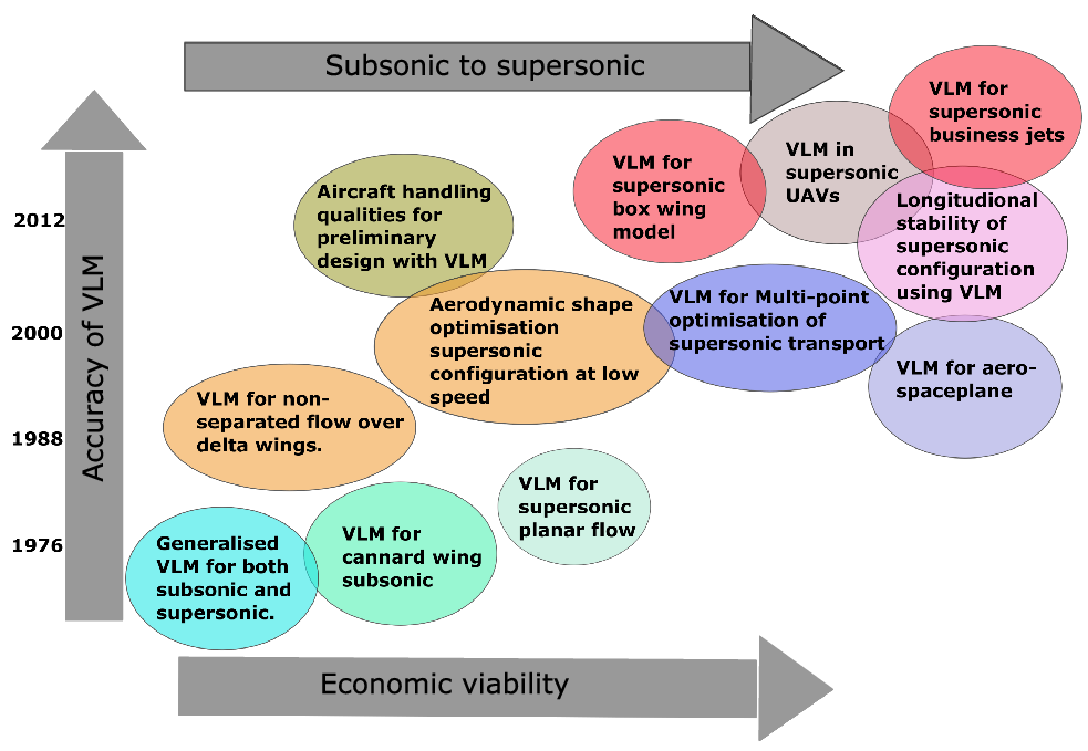
The roadmap of the vortex lattice method for its application for supersonic configuration is shown in Fig. 18. The journey started with the development of VLM by Miranda for its generalised use for subsonic and supersonic configuration [Reference Miranda, Elliott and Baker80]. The method gained popularity when the accuracy of VLM was close to conventional CFD solver for subsonic conditions. Starting its analysis for canard wing configuration for subsonic conditions [Reference Rom, Melamed and Almosnino81]. Further development of supersonic VLM was carried forward with its application by studying the planar flow at supersonic speeds improving on the limitations of the VLM [Reference Nangia, Palmer and Doe82]. Within a decade of development and use of VLM for subsonic configuration, the solver was used effectively in studying the flow separation over the delta wing [Reference Ghaffari and Lamar83]. The use of VLM in stability and flow separation conditions was quite an effective and efficient analysis. The early 21st century comes with solving one of the biggest design problems with supersonic configuration in research for reducing sonic boom capabilities, making them equally efficient at low speeds [Reference Mavriplis, Ting, Moustafa, Hill, Soltani, Nelson and Livne79] and improving the longitudinal stability at low speeds [Reference Smelsky84] for which supersonic VLM was the most efficient method for making preliminary predictions. The recent use of VLM for supersonic configuration was used to study the spaceplane [Reference Griffin and Takahashi85], in supersonic UAVs and supersonic business jet design [Reference Seraj and Martins86], and more details are shown in Table 5. For the next generation of supersonic aircraft low boom is the biggest design challenge for which the study of dynamic stability is critical to examine. Dynamic stability at take-off and landing can be readily examined with a help of VLM [Reference Magee, Hayes, Khodadoust and Dorgan87]. Boeing UDP which is based on Ames’s (Woodward) subsonic supersonic wing body panel method program was used to study the dynamic stability of non-planar configuration and winglets deformations [Reference Rao, Chatterjee, Landrum and Kanistras88] which utilises Carlson’s leading edge thrust correction and vortex lift correction which proves to be a cheap alternative to analyse the stability derivatives than conventional solvers. When it comes to work done in designing the supersonic configuration using low-fidelity tools, the University of Michigan worked in the development of UVLM code enhanced with the Polhamus method [Reference Polhamus89] and combined with corrections from the wind tunnel experiments developed a solver with adequate fidelity while capturing the prevalent vortex phenomenon [Reference Guimarães, Cesnik and Kolmanovsky90] involved in high angle-of-attack and low-speed manoeuvers. Baseline supersonic configuration SCALOS was used to support the investigation to enable future parametric investigation [Reference Mavriplis, Ting, Moustafa, Hill, Soltani, Nelson and Livne79].
Roadmap of VLM for supersonic configurations.
Use of vortex lattice methods in supersonic configuration

Such MDO tools work out potential solutions for multi-objective performance indices which, in the case of supersonic aircraft, can be in reducing compressibility drag, the distribution, and strength of shock waves, or the magnitude of the noise from sonic booms. In the past with the initiation of SST, there were many problems in improving these limitations [Reference Smith13, Reference Banerjee91]. A lack of research and computational power to run the analysis for several different flight conditions and for different supersonic flows limited development in optimised supersonic designs. But with improved potential flow solver methods and their integration with much more efficient and powerful computer languages, there is more capability than before of supporting low-cost supersonic aircraft design. Substantial research is now underway to reduce the impact of sonic booms [Reference Li and Rallabhandi92]. With the latest design improvements one can theoretically bring down the sonic boom noise level to normal hearing conditions [Reference Chung and Alonso93–Reference Li, Shields and Geiselhart95].
Such research is majorly favoured by a fair number of new supersonic business jet companies, which are relying on modern computational capabilities to bring new designs to the market much faster than previous aircraft design schedules. Companies such as Gulfstream Aero, Boom supersonic, and many more [Reference Smith13] are currently working on quiet supersonic business jets. One such example by the Northrop Grumman concept is shown in Fig. 19. Use of VLM has been seen trending with studies for aerodynamic shape optimisation for supersonic transport especially considering the low-speed stability. VLM was used to study the low-speed constraint during optimisation for augmented vortex analysis for stability derivative computation based on the pitch-up estimation method to capture non-linear pitch-up characteristics in the model. The paper demonstrated the capabilities of VLM for highlighting the trade-offs between supersonic performance and subsonic stability. More work was carried forward with pitching moment approximation for the MDO of HSCT. Low-order VLM was used with a pitch-up estimation method to capture non-linear pitch-up characteristics in the model [Reference Benoliel and Mason96].
Northrop Grumman QSP concept [Reference Smith13].

4.3 Mach-cone influence in VLM for supersonic configurations
Subsonic and supersonic wing theories and other low-order solvers such as doublet, and vortex distribution have been reviewed and a systematic correction approach is provided, which might be able to improve the correction factor associated with the accuracy of VLM for supersonic flow. It shows that care must be taken in the treatment of singularities involved in the analysis. In the development of the TORNADO’s supersonic module [Reference Estrada, Melin and Estrada97] it is clearly seen the integration of Mach cone for the delta wing analysis is shown in Fig. 20. The relation of Mach angle with Mach speeds explaining increasing the Mach number decreases the Mach angle. This explains that as the flow is compressed the shock angle and the speed change with a change in temperature. The angle of the shock changes greatly with an increase in the Mach angle. To prevent this coalesce of pressure change the wing span will need to be changed which is affected by shock. Such influence of Mach cone is critical in designing supersonic configuration. Mach cone influence can also benefit from the shift in collocation point of the panels when transitioning from subsonic to supersonic speeds. We know that a change in Mach angle changes the shock’s apex location, which in theory should also change the panel collocation points. When computed for the transition to supersonic speeds, these changes in location will help improve the solver’s accuracy.
Mach cone influence on the delta wing [Reference Estrada, Melin and Estrada97].

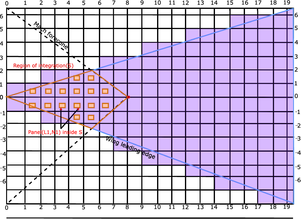
Influence of the continuous distribution of horseshoe vortices originating from wing elements divided into a number of small panels with small chord lengths and spans are shown in Fig. 21 The region of integration S stretches on the wing planform inside the Mach forecone originating from the field point (x,y). The panel selection and position are influenced in relation to the Mach forecone. The change in the Mach forecone triggers the selection of panels which influence the design change of the wing for supersonic flows.
Panel representation of flat plate delta wings with subsonic leading edge [Reference Guillermo-Monedero, Whitfield, Freuler and Mccrink114].
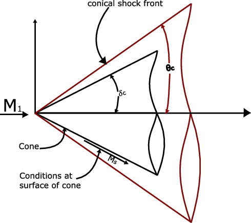
It is the common practice to predict pressure distribution over a cone at high-speed wind channel using Taylor MacColl equation for studying the relation between oblique shock waves and Mach cone which states the normal velocity component on the cone surface becomes small. The Taylor MacColl implementation with hypervelocity calculation by Ishimatsu [Reference Ishimatsu and Morishita98] has the potential to determine the change in velocity of the panels during its transitions from subsonic to supersonic speeds. The method can be implemented for each panel on the wing assuming each panel as a wing in itself going through supersonic flow experiences a shock cone as shown in Fig. 22. With the relation between the shockwave and the Mach cone of the panels, the velocity correction will be helpful in predicting the change in pressure distribution on the panels hence improving the accuracy of VLM for supersonic speeds.
 \begin{align}\left(1 - \frac{{{v^2}}}{{{a^2}}}\right)\frac{{{{\rm{d}}^{\rm{2}}}{\rm{u}}}}{{{\rm{d}}{\theta ^2}}} + cot\theta \frac{{{\rm{du}}}}{{{\rm{d}}\theta }} + \left(2 - \frac{{{v^2}}}{{{a^2}}}\right)u = 0\end{align}
Where $a$
: is the local speed of sound,
$a$
: is the local speed of sound, $u$
: the velocity component in a radial direction,
$u$
: the velocity component in a radial direction, $v$
: is the velocity component in
$v$
: is the velocity component in $\theta $
direction and
$\theta $
direction and $\theta $
is the circumferential coordinate. As the velocity normal component on the cone surface is zero and even goes smaller relative to
$\theta $
is the circumferential coordinate. As the velocity normal component on the cone surface is zero and even goes smaller relative to $u$
in the shock-layer at hypervelocity. Equation (1) can be written as:
$u$
in the shock-layer at hypervelocity. Equation (1) can be written as:
 \begin{align}\frac{{{{\rm{d}}^{\rm{2}}}u}}{{{\rm{d}}{\theta ^2}}} + cot\theta \frac{{{\rm{d}}u}}{{{\rm{d}}\theta }} + 2u = 0\end{align}
when radial direction velocity component is defined usually as $u(\theta ) = f(\theta )cos\theta $
which makes Equation (2) as:
$u(\theta ) = f(\theta )cos\theta $
which makes Equation (2) as:
 \begin{align}\frac{{\rm{d}}}{{{\rm{d}}\theta }}\left(\sin \theta co{s^2}\theta \frac{{{\rm{d}}f}}{{{\rm{d}}\theta }}\right) = 0\end{align}
Taylor MacColl equation representing of shock layer and oblique shock relationship for hyper-velocity flow [Reference Ishimatsu and Morishita98].
Equation (3) can be integrated analytically and $u(\theta ) = f(\theta )cos\theta $
becomes:
$u(\theta ) = f(\theta )cos\theta $
becomes:
 \begin{align}u(\theta ) = A\!\left[1 + cos\theta .\ln \tan \frac{\theta }{2}\right] + B\cos \theta \end{align}
Remaining Taylor Maccoll equation yields:
 \begin{align}v(\theta ) = \frac{{{\rm{d}}u}}{{{\rm{d}}\theta }} = A\!\left[\!\cot \theta - \sin \theta .\ln \tan \frac{\theta }{2}\right] - B\sin \theta \end{align}
in Equations (4) and (5), A and B are integration constants, and these values can be determined from the oblique shock conditions:
 \begin{align}u(\beta ) = {V_1}\cos \beta \end{align}
 \begin{align}v(\beta ) = - \frac{1}{\rho }{V_1}\sin \beta \end{align} ${V_1}$
is the uniform velocity and
${V_1}$
is the uniform velocity and $\rho $
is the density ratio across the shock wave given by:
$\rho $
is the density ratio across the shock wave given by:
 \begin{align}\rho \equiv \frac{{{\rho _2}}}{{{\rho _1}}} = \frac{{(\gamma + 1)M_1^2\mathop {\sin }\nolimits^2 \beta }}{{(\gamma - 1)M_1^2si{n^2}\beta + 2}}\end{align}
where $M$
: is Mach number,
$M$
: is Mach number, $\beta $
: shock-wave angle,
$\beta $
: shock-wave angle, $\gamma $
: specific heat ratio,
$\gamma $
: specific heat ratio, ${\rho _1}$
is the density of uniform flow and
${\rho _1}$
is the density of uniform flow and ${\rho _2}$
is the density of shock behind. From Equations (4-7) we have:
${\rho _2}$
is the density of shock behind. From Equations (4-7) we have:
 \begin{align}A = \left(1 - \frac{1}{\rho }\right){V_1}\mathop {\sin }\nolimits^2 \beta \cos \beta \end{align}
 \begin{align}B = {V_1} - \left[\left(1 - \frac{1}{\rho }\right){V_1}\mathop {\sin }\nolimits^2 \beta \cos \beta \right] \times \left(\frac{1}{{\cos \beta }} + \ln \tan \frac{\beta }{2}\right)\end{align}
This bring down the hypervelocity equation to as follows:
 \begin{align}\frac{u}{{{V_1}}} = \cos \theta + \left(1 - \frac{1}{\rho }\right)\mathop {\sin }\nolimits^2 \beta \cos \beta \!\left[1 - \frac{{\cos \theta }}{{\cos \beta }} + \cos \theta .\ln \frac{{\tan \frac{\theta }{2}}}{{\tan \frac{\beta }{2}}}\right]\end{align}
 \begin{align}\frac{v}{{{V_1}}} = - \sin \theta + \left(1 - \frac{1}{\rho }\right)\mathop {\sin }\nolimits^2 \beta \cos \beta\!\left[\cot \theta + \frac{{\sin \theta }}{{\cos \beta }} - \sin \theta .\ln \frac{{\tan \frac{\theta }{2}}}{{\tan \frac{\beta }{2}}}\right]\end{align}
The Equations (11) and (12) used for hypervelocity prediction of high-speed hypersonic aerodynamics can be very easily implemented for supersonic configuration for supersonic speeds. Assuming each lattice or panel as a wing going through supersonic speeds encounters a shock wave can be solved to predict the change in velocity component on the panels surface which will very well helpful in predicting the pressure changes on the panel surface, improving the supersonic VLM accuracy.
4.3.1 Warp-wing design using VLM
The wing with a larger sweep angle and low aspect ratio is often used to often reduce the wave drag and its influence at supersonic speeds. Keeping this configuration satisfies one application but does not perform well under low-speed take-off and landing. To overcome this problem a large area of the wing is required to generate lift and consequently reduce the take-off and landing length, which leads to an increase in aircraft weight leading to inefficient flight. Work has been done with regards to the use of VLM in design optimisation of such configuration of wing keeping in mind the required performance index changing design parameters to achieve its goal of efficient flight using a combination of Quasi-vortex lattice method [Reference Lan99] and leading edge suction analogy [Reference Higuchi, Zhong and Rinoie100]. A new multi-point design method approach was used to design an improving lift with reducing the wing area and weight which was majorly suitable for supersonic business jet configurations. The work shows that by using the supersonic wing theory and Carlson’s warp wing theory in iSIGHT-FD wing planforms are optimised at supersonic cruising speeds. Use of VLM with dividing the wings into No. of panels chordwise and spanwise focusing more on leading edge flap as shown in Fig. 23 and trailing edge flaps which reduces the lift dependent drag by increasing the number of panels on focused surfaces make desired design changes keeping the arbitrary shape intact. Lift dependent drag is usually reduced by combining camber and twist distribution to optimise the pressure distribution on the surface panels working out making relevant design changes.
Warp wing design using VLM.

4.4 Compressibility correction and drag divergence integration with vortex lattice method
For incompressible flow the change in density due to expansion and compression of fluid is small enough that it can be ignored to save a large amount of simulation cost. On the other hand, and especially when the flow is supersonic, with a significant expansion and compression of fluid being appreciable, compressible fluid analysis that considers density variation is required. To treat the compressible fluid a pressure-based calculation method is used, though in the case of high Mach numbers a density-based calculation method is preferred. To predict the effect of compressibility on down-wash interaction is proposed by Vaessen [Reference Vaessen and Vos101], which works on the compressibility correction factor k with vortex lattice method determining its influence on down-wash as shown in Fig. 24 and making relevant decision on design changes. the accuracy of the solver proposed was dependent on how close the tip vortex from the canard passes from the main wing.
Structure of an N × N vortex lattice influence matrix for compressibility calculations [Reference Vaessen and Vos101].

VLM and modern implementations of UVLM model the steady and unsteady potential flow around a lifting surface for different flow conditions and parameters with the influence of vortex points or vortex rings. However, current advancement and overall VLM theory, in general, do not deal much the implementation of high-speed (compressibility) drag calculation and the amount of work done in the past in regard to this is much less than in other areas. Compressibility correction factors for standard steady VLM are typically introduced by the Prandtl-Glauert (PG) correction factor [Reference Hess, Valarezo, Ballmann, Eppler and Hackbusch38, Reference Lees102], based on the rule which states that the pressure coefficient, ${C_p}$
, at any point on a thin aerofoil surface in a compressible flow is
${C_p}$
, at any point on a thin aerofoil surface in a compressible flow is ${(1 - M_\infty ^2)^{1/2}}$
times the pressure coefficient at the same point on the same aerofoil in incompressible flow. The solution for the compressible flow of VLM is solved for the incompressible domain and then modified with the correction. Karman and Tsien [Reference Coburn103] proposed a two-dimensional subsonic flow perfectly with irrotational, compressible fluid by replacing the adiabatic pressure-volume curve with a tangent line drawn at an arbitrary point on this curve. An extension of this Karman-Tsien method to supersonic jet flow was made by Coburn [Reference Coburn104]. The basic partial differential equations satisfied by the velocity potential in a general three-dimensional domain were derived from the Eulerian momentum equations, the continuity conditions, and with respect to the relation between the speed of pressure and propagation [Reference Steinhoff and Underhill105]. These relations are all analytically mentioned in literature [Reference Sears106, Reference Millikan107]. With regard to the PG rule, the prediction of induced drag is not included for three-dimensional flow. The higher-order methods require the direct use of a pressure coefficient which is not available in conventional VLM. VLMs already in use produce a delta pressure coefficient (
${(1 - M_\infty ^2)^{1/2}}$
times the pressure coefficient at the same point on the same aerofoil in incompressible flow. The solution for the compressible flow of VLM is solved for the incompressible domain and then modified with the correction. Karman and Tsien [Reference Coburn103] proposed a two-dimensional subsonic flow perfectly with irrotational, compressible fluid by replacing the adiabatic pressure-volume curve with a tangent line drawn at an arbitrary point on this curve. An extension of this Karman-Tsien method to supersonic jet flow was made by Coburn [Reference Coburn104]. The basic partial differential equations satisfied by the velocity potential in a general three-dimensional domain were derived from the Eulerian momentum equations, the continuity conditions, and with respect to the relation between the speed of pressure and propagation [Reference Steinhoff and Underhill105]. These relations are all analytically mentioned in literature [Reference Sears106, Reference Millikan107]. With regard to the PG rule, the prediction of induced drag is not included for three-dimensional flow. The higher-order methods require the direct use of a pressure coefficient which is not available in conventional VLM. VLMs already in use produce a delta pressure coefficient ( $\Delta {C_p}$
) distributing the differences in pressure between the top and bottom aerofoil surfaces. Because the use of higher order correction is not applicable, and the PG rule is preferred for calculation in the three-dimensional domain, the vortices are computed as usual using VLM for incompressible strength distribution and are followed by compressible vortex distribution. After that, the incompressible vortex strength at each panel is multiplied by the PG correction factor. The induced velocity from the vortex core is calculated using compressible vortex strength and compressible vortex-induced velocity in three-dimensional space form is added to the velocity contribution from the free stream and aircraft rotation. The compressible vorticity and effective velocity at the vortex core are then used to compute the force vector acting on each panel and the force distribution is integrated to calculate the forces and moments to predict the pressure distribution on the surface. This method proved very effective and was highly accurate and efficient as a three-dimensional VLM but has certain limitations with regard to supersonic conditions and large angles of attacks. A compressible VLM has been used to study the interaction of a profile wing with a convicted vortex passing under the profile, commonly known as blade vortex interaction. The technique applied to an aerofoil is known as aerofoil vortex interaction [Reference Hernandes and Soviero108]. The PG correction method is presently used in TORNADO’s MATLAB code [Reference Estrada, Melin and Estrada97] and shows promising results when compared to other methods. Still, the implementation for the prediction of compressibility correction and drag divergence prediction for three-dimensional supersonic flight conditions is still missing. As most of the three-dimensional research for the conceptual design phase for supersonic aircraft is done under cruise conditions, the accurate modeling of drag divergence is not required. Prediction of drag divergence [Reference Takahashi, German, Shajanian, Daskilewicz and Donovan109] and drag reduction [Reference Lovell110] is still a vital area of study for supersonic aircraft design for its operation in low subsonic speeds during lift and initial maneuvers before reaching cruising supersonic speeds [Reference Lovell110].
$\Delta {C_p}$
) distributing the differences in pressure between the top and bottom aerofoil surfaces. Because the use of higher order correction is not applicable, and the PG rule is preferred for calculation in the three-dimensional domain, the vortices are computed as usual using VLM for incompressible strength distribution and are followed by compressible vortex distribution. After that, the incompressible vortex strength at each panel is multiplied by the PG correction factor. The induced velocity from the vortex core is calculated using compressible vortex strength and compressible vortex-induced velocity in three-dimensional space form is added to the velocity contribution from the free stream and aircraft rotation. The compressible vorticity and effective velocity at the vortex core are then used to compute the force vector acting on each panel and the force distribution is integrated to calculate the forces and moments to predict the pressure distribution on the surface. This method proved very effective and was highly accurate and efficient as a three-dimensional VLM but has certain limitations with regard to supersonic conditions and large angles of attacks. A compressible VLM has been used to study the interaction of a profile wing with a convicted vortex passing under the profile, commonly known as blade vortex interaction. The technique applied to an aerofoil is known as aerofoil vortex interaction [Reference Hernandes and Soviero108]. The PG correction method is presently used in TORNADO’s MATLAB code [Reference Estrada, Melin and Estrada97] and shows promising results when compared to other methods. Still, the implementation for the prediction of compressibility correction and drag divergence prediction for three-dimensional supersonic flight conditions is still missing. As most of the three-dimensional research for the conceptual design phase for supersonic aircraft is done under cruise conditions, the accurate modeling of drag divergence is not required. Prediction of drag divergence [Reference Takahashi, German, Shajanian, Daskilewicz and Donovan109] and drag reduction [Reference Lovell110] is still a vital area of study for supersonic aircraft design for its operation in low subsonic speeds during lift and initial maneuvers before reaching cruising supersonic speeds [Reference Lovell110].
5.0 Outlook
After analysis and review of the literature, it can be said that much work for the improvement of VLM methods for supersonic regimes can be achieved by implementing the use of Mach cone influence for the supersonic conditions which will give a better understanding of collocation point at high speed to predict vortex edge separation. One of the limitations of TORNADO’s supersonic module [Reference Estrada, Melin and Estrada97] is accurately predicting the position of collocation points on panels during its transition from subsonic to supersonic flow. To overcome this challenge, Mach cone influence can be used in predicting the correct position of collocation points which helps in reducing the influence lost at supersonic speeds. Compressibility correction accuracy for supersonic flow, as with the current state uses the PG rule to re-evaluate the compressibility correction factor which works best for subsonic speed and loses its accuracy with increasing Mach number. Improving accuracy can be achieved by implementing the use of the hybrid lattice Boltzmann method (HLBM) [Reference Renard, Feng, Boussuge and Sagaut111], which shows very promising results with the subsonic and supersonic flow with or without shocks. The proposed model is shown to be an efficient, accurate and robust alternative to classical Navier–Stokes methods. Integration of this model with the TORNADO module can achieve high accuracy with improved product design capabilities for future supersonic aircraft.
In the case of conceptual design, the conventional approach is to carry out aerodynamic shape optimisation by introducing an optimisation loop over a set of results to work out the best choice of design which can satisfy the given performance index. Aerodynamic shape optimisation can be achieved with different types of optimisers for faster and more accurate predictions. Modern optimisers work with multiple dimensional or performance constraints so that the final result can be bounded within known requirements. In a quest to improve overall efficiency, a VLM can be used in an adjoint-based optimisation approach. The application of this approach has been explored with hypersonic and supersonic missile design [Reference Damm66]. A similar approach has been used to design both 2D and 3D aerodynamics of different wing configurations for transonic speeds [Reference Brezillon and Gauger67]. VLM and the various developments since its inception have been shown to be highly suitable lower-order solvers to facilitate optimisation work. The same could also be the case for supersonic aircraft design, with future work to advance the accuracy of VLMs for higher-speed regimes. The future outlook for improvements can also be achieved by including nonlinear and unsteady flow modeling for improving the prediction of unsteady aerodynamic characteristics and aeroelastic behaviours in supersonic flow. The prevalence of open-source VLM solvers in the research community means there is fertile ground to develop and implement such improved modelling capabilities and lead to easier integration with more complex and detailed modeling frameworks.


 Open access