


Introduction
As artificially periodic composites, phononic crystals (PCs) have been attracting more and more attention for the last three decades (Laude, Reference Laude2015). They can exhibit bandgaps in certain frequency ranges, within which the propagation of acoustic or elastic waves is prohibited (Sigalas and Economou, Reference Sigalas and Economou1992). Generally, there are two main mechanisms for bandgap generation: Bragg scattering and local resonance (Kushwaha et al., Reference Kushwaha, Halevi, Dobrzynski and Djafari-Rouhani1993; Liu et al., Reference Liu, Zhang, Mao, Zhu, Yang, Chan and Sheng2000). Bragg bandgaps are mainly dependent on the structural periodicity. The corresponding wavelength is in the same order with the lattice constant. While in contrast resonant bandgaps are mainly dependent on the resonance of the scatterers. The wavelength inside the bandgap is much larger than the lattice constant. The nature of bandgaps can be used for vibration reduction (Niousha and Motosaka, Reference Niousha and Motosaka2001; Assouar et al., Reference Assouar, Senesi, Oudich, Ruzzene and Hou2012; Zeng et al., Reference Zeng, Yang, Deng, Zeng, Yang, Muzamil and Qiujiao2018), and sound isolation (Martinez-Sala et al., Reference Martinez-Sala, Rubio, Garcia-Raffi, Sanchez-Perez, Sanchez-Perez and Llinares2006; Maldovan, Reference Maldovan2013; Wang et al., Reference Wang, Laude and Wang2014).
When one or some scatterers are removed or replaced with different shapes or materials, the periodicity of PCs is broken. Defected states are then induced inside the bandgap (Sigalas, Reference Sigalas1997, Reference Sigalas1998; Li et al., Reference Li, Chen, Wang, Ma and Jiang2014) and can be used to design novel wave devices. Point, linear, and planar defects can be obtained by modifying one, one line or one layer of scatterers. Wave or energy can be trapped around the point defect, so point defects might be applied for the design of novel cavity (Torres et al., Reference Torres, Montero de Espinosa, Garcia-Pablos and Garcia1999; Khelif et al., Reference Khelif, Choujaa, Djafari-Rouhani, Wilm, Ballandras and Laude2013) or energy harvester (Liang-Yu et al., Reference Liang-Yu, Chen and Liu2009; Jo et al., Reference Jo, Yoon, Shin, Choi, Park, Kim and Youn2020). A linear defect can be used to confine the energy around the defect and guide the propagation of energy. So they can be used to design waveguides (Khelif et al., Reference Khelif, Choujaa, Benchabane, Djafari-Rouhani and Laude2004; Li and Liu, Reference Li and Liu2005). This can also be realized by using a linear chain of point defects (Wang et al., Reference Wang, Wang, Liang, Wang and Laude2018a). Planar defect introduces modes with energy localized in the plane (Psarobas et al., Reference Psarobas, Stefanou and Modinos2000). Combination of different defects can be used to design various wave devices, such as filter, coupler, splitter, and frequency demultiplexer (Pennec et al., Reference Pennec, Djafari-Rouhani, Vasseur, Khelif and Deymier2004, Reference Pennec, Djafari-Rouhani, Vasseur, Larabi, Khelif, Choujaa, Benchabane and Laude2005; Wang et al., Reference Wang, Wang, Liu, Wang and Laude2018b).
Despite the existence of the above wave behaviors, practical applications of PCs are rarely demonstrated because the operating frequency ranges of the PC-based devices are generally fixed. The concept of tunable PCs has thus been developed as a separate research field (Wang et al., Reference Wang, Wang, Bin, Chen and Wang2020). Generally, there are two main regulation mechanisms. On the one side, tunable PCs are realized by physically adjusting the material parameters. Such systems generally consist of multiphysics coupled media, which are sensitive to the electric field (Li et al., Reference Li, Chen, Hu and Huang2018; Ning et al., Reference Ning, Wang and Wang2021; Zhang and Gao, Reference Zhang and Gao2021), magnetic field (Yang et al., Reference Yang, Li, Wen, Caijiang, Peng, Zhang, He, Wang and Yang2014; Chunlong and Jin, Reference Chunlong and Jin2016; Gao et al., Reference Gao, Yang, Hong, Guo, Sun and Sun2023), optical field (Baumgartl et al., Reference Baumgartl, Zvyagolskaya and Bechinger2007), and thermal field (Chuang et al., Reference Chuang, Lv and Wang2019; Liu et al., Reference Liu, Huo, Feng, Huang and Chen2019; Yang et al., Reference Yang, Zhou and Wang2022). On the other hand, tunable PCs are realized by mechanically changing the geometrical topology. In addition to filling fluid in PCs with blind holes (Wang et al., Reference Wang, Wang, Wang and Laude2017a; Wang et al., Reference Wang, Wang, Deng, Laude and Wang2023), prestress is commonly used to tune wave propagation. Apart from granular PCs (Allein et al., Reference Allein, Tournat, Gusev and Theocharis2016; Kim et al., Reference Kim, Martinez, Phenisee, Kevrekidis, Porter and Yang2018), the related investigations on the continuous prestressed PCs generally include two parts.
First, some investigations focus on PCs with traditional elastic materials. Gei et al. (Reference Gei, Movchan and Bigoni2009) investigated flexural wave propagation in the prestressed periodic beam on an elastic foundation. They showed that bandgaps can be shifted upward (downward) for tensile (compressive) prestress. Wang et al. (Reference Wang, Li, Kishimoto, Wang and Huang2010) calculated the effects of prestress on the bandgaps of three-dimensional pizeoelectric PCs. The location of bandgaps was found to increase with increasing prestress, while the width of bandgap remains almost unchanged. Zhu et al. (Reference Zhu, Sun, Song, Wen, Liu, Feng and Liu2021) studied the bandgap adjustability under prestretch strain. Applying prestretch strain to the matrix can realize active real-time control of low-frequency bandgap under slight deformation and broaden the low-frequency bandgap. Li et al. (Reference Li, Wang and Wang2020) showed that the frequency ranges of nonreciprocal transmission can be shifted down for elastic waves propagating in the combination of nonlinear material and elastic metamaterials with increasing prestress. Large stresses, however, are required for significant tunability of the elastic materials (Feng and Liu, Reference Feng and Liu2012).
Second, some investigations considered PCs with hyperelastic materials. Compared to their elastic counterparts, hyperelastic materials generate large deformation even under a small stress. Bertoldi’s group has investigated wave propagation in several soft porous PCs under prestress (Bertoldi and Boyce, Reference Bertoldi and Boyce2008a, Reference Bertoldi and Boyce2008b). Novel configuration patterns based on the instability and bulking provide rich room to tune the wave behaviors (Shan et al., Reference Shan, Kang, Wang, Qu, Shian, Chen and Bertoldi2014). Sharma et al. (Reference Sharma, Joglekar, Joglekar and Alam2022) investigated the optimal topologies of the soft compressible unit cells for varying levels of the tensile and compressional prestress. They observed that increasing the lateral tensile prestress together with applying a compressional longitudinal prestress has favourable impacts on widening the bandgaps. Bayat and Gordaninejad (Reference Bayat and Gordaninejad2015) formed wrinkles in 1D prestressed PC slab composed of a thin soft film attached to a thick substrate. The bandgaps were adjusted by surface instability. Chen et al. (Reference Chen, Wu, Su and Chen2019) realized a tunable soft acoustic diode in the bandgap by changing the applied force. De Pascalis et al. (Reference De Pascalis, Donateo, Ficarella and Parnell2020) employed genetic algorithm to optimize prestressed phononic media for the low-frequency bandgaps of antiplane elastic waves. Miniaci et al. (Reference Miniaci, Mazzotti, Amendola and Fraternali2021) found a remarkable shift of dispersion curves for inertial amplified PCs compared to Bragg or resonant ones. More related work may be found in the recent review (Bertoldi et al., Reference Bertoldi, Vitelli, Christensen and van Hecke2017).
Although there is a lot of literature on prestressed PCs, investigations on the defected PCs are rarely reported (Wang et al., Reference Wang, Li, Yuxin, Bao, Chen and Wang2021b), especially for Lamb waves. Manipulation of Lamb waves by PCs combining prestress and defects remains a difficult task. In this paper, we design and fabricate dual-tunable waveguides in a two-dimensional periodic plate with threaded holes. Dual tunability is realized by using rods held with nuts as well as assembly prestress of the nuts. Guided waves can be tuned by adjusting the distribution of rods and nuts in different circuits and controlling the amount of assembly prestress. Straight waveguides, bent waveguides, and wave splitters are designed by changing the distribution of rods and nuts in different circuits. The frequencies of guided waves are tuned by the assembly prestress. Confinement, guiding, and splitting of Lamb waves are clearly observed in both experimental measurements and numerical simulations. This work is important for the design of reconfigurable or programmable elastic wave devices.
Experimental and numerical methods
Figure 1a shows a photograph of the dual-reconfigurable phononic splitter fabricated on a PC plate with threaded holes. The splitter is composed of three straight waveguides, where the threaded rods are assembled on the plate by four nuts placed symmetrically on both sides. The assembly prestress is controlled precisely by a digital torque wrench with 2% accuracy and 0.2–10 N $\cdot $
m range. Note that the exact prestress or prestrain that is applied experimentally is not quantitatively known, though precisely set relatively. An additional benefit of the use of the digital torque wrench is that prestress can be equilibrated on all assemblies to obtain the same resonance frequency for all defects. The asymmetric wave source is excited by the vertically polarized piezoelectric patch glued on one side of the plate, which excites Lamb waves. And, the piezoelectric patch is positioned away from the edge of the plate, minimizing the inference of reflected waves on the experimental results. Experimental measurements are conducted by using Polytec PSV-500 scanning vibrometer. Transmission properties and displacement distribution of waveguides are measured by considering harmonic excitation with stepped or fixed frequencies. The signals are amplified before being applied to the piezoelectric patch. The excitation source is asymmetric with respect to the mid-plane of the plate, which is beneficial to the excitation of out-of-plane modes. However, due to the finite lateral extent of the source (Wang et al., Reference Wang, Wang, Liu, Wang and Laude2018b), in-plane modes may be excited as well.
$\cdot $
m range. Note that the exact prestress or prestrain that is applied experimentally is not quantitatively known, though precisely set relatively. An additional benefit of the use of the digital torque wrench is that prestress can be equilibrated on all assemblies to obtain the same resonance frequency for all defects. The asymmetric wave source is excited by the vertically polarized piezoelectric patch glued on one side of the plate, which excites Lamb waves. And, the piezoelectric patch is positioned away from the edge of the plate, minimizing the inference of reflected waves on the experimental results. Experimental measurements are conducted by using Polytec PSV-500 scanning vibrometer. Transmission properties and displacement distribution of waveguides are measured by considering harmonic excitation with stepped or fixed frequencies. The signals are amplified before being applied to the piezoelectric patch. The excitation source is asymmetric with respect to the mid-plane of the plate, which is beneficial to the excitation of out-of-plane modes. However, due to the finite lateral extent of the source (Wang et al., Reference Wang, Wang, Liu, Wang and Laude2018b), in-plane modes may be excited as well.
Dual-tunable phononic splitter. (a) Photograph of the wave splitter and the Digital Torque Wrench used to evaluate the assembly prestress. (b) Supercell of waveguide used to calculate the band structure.

Numerical simulations are conducted by using the finite-element software COMSOL. The assembly prestress is taken into account through prestrain in the Solid Mechanics Module. Before solving for the band structures or transmission properties of the structures, a stationary study is performed to calculate the static deformation of the structure under the prestress. The geometrical and material parameters of the plate, rods, and nuts are exactly the same with those in (Wang et al., Reference Wang, Yang, Wang, Chen, Laude and Wang2021c). Figure 1b illustrates the supercell of the waveguide used for the calculation of band structures. The plate is divided into four parts in the thickness direction. Quadratic serendipity element is applied to approximate the displacement field. Periodic Bloch boundary conditions are applied along the x- and y-directions, and the other surfaces are set as traction-free. The band structure is obtained by sweeping the wave vector along the irreducible Brillouin zone of the supercell. Eigenmodes at the marked points are also obtained by choosing the suitable wavenumber and frequency. In addition, the polarization amounts for the out-of-plane modes are calculated based on the eigenmodes. They represent the contribution of out-of-plane displacements to the total polarization of elastic waves.
Transmission properties are evaluated by considering a 3D plate model. An asymmetric wave source is applied to the top of the plate. The response is collected in the region $S_1$
(with the area
$S_1$
(with the area $A_1$
) on the end of the waveguides. We define the numerical transmission as
$A_1$
) on the end of the waveguides. We define the numerical transmission as
 $$ \begin{align} F=20\text{log}_{10}\left(\frac{\int_{S_1}|U_1|/A_1dS}{|U_0|}\right), \end{align} $$
where $U_0=1$
is the amplitude of the z-polarized wave source and
$U_0=1$
is the amplitude of the z-polarized wave source and $U_1$
is the total displacement received on the end of the waveguides (
$U_1$
is the total displacement received on the end of the waveguides ( $S_1$
).
$S_1$
).
Results and discussions
In this section, we discuss the band structures and transmission properties of dual tunable waveguides with different prestress.
Defect modes of prestressed waveguides
First, we investigate the band structures and defect modes of prestressed waveguides. The supercell is shown in Figure 1a. For comparison, we also consider the phononic waveguides assembling by rods and nuts with perfect bonds. Band structure of the waveguide with perfect bond is presented in Figure 2a, together with the vibration modes of the defected bands in the marked points. It is observed that the band structure is different from that in Wang et al. (Reference Wang, Yang, Wang, Chen, Laude and Wang2021c) because two nuts are added on both sides of the plate. This also indicates the reconfigurability of the proposed waveguide. The defect mode at point P1 is flexural-dominated but asymmetric with respect to the wave propagation direction. So it is a deaf mode and cannot be excited by a symmetric plane wave. This also holds for the defect mode at point P3. So only the defect mode at point P2 contributes to the transmission.
Band structures and vibration modes of the phononic waveguides with perfect bonds (a) or different prestrains: (b) 0.0083 and (c) 0.0167.
Note: The colour scale represents the polarized amount from 0 (blue) to 1 (red). The light-grey areas indicate the passing band for the out-of-plane polarized waves in the perfect PC slab. The dark-grey areas indicate the considered frequency range of guided bands. Vibration modes at marked points are shown on the right. The colour scale represents the normalized amplitude of out-of-plane displacements from $-1$
(blue) to 1 (red).
$-1$
(blue) to 1 (red).
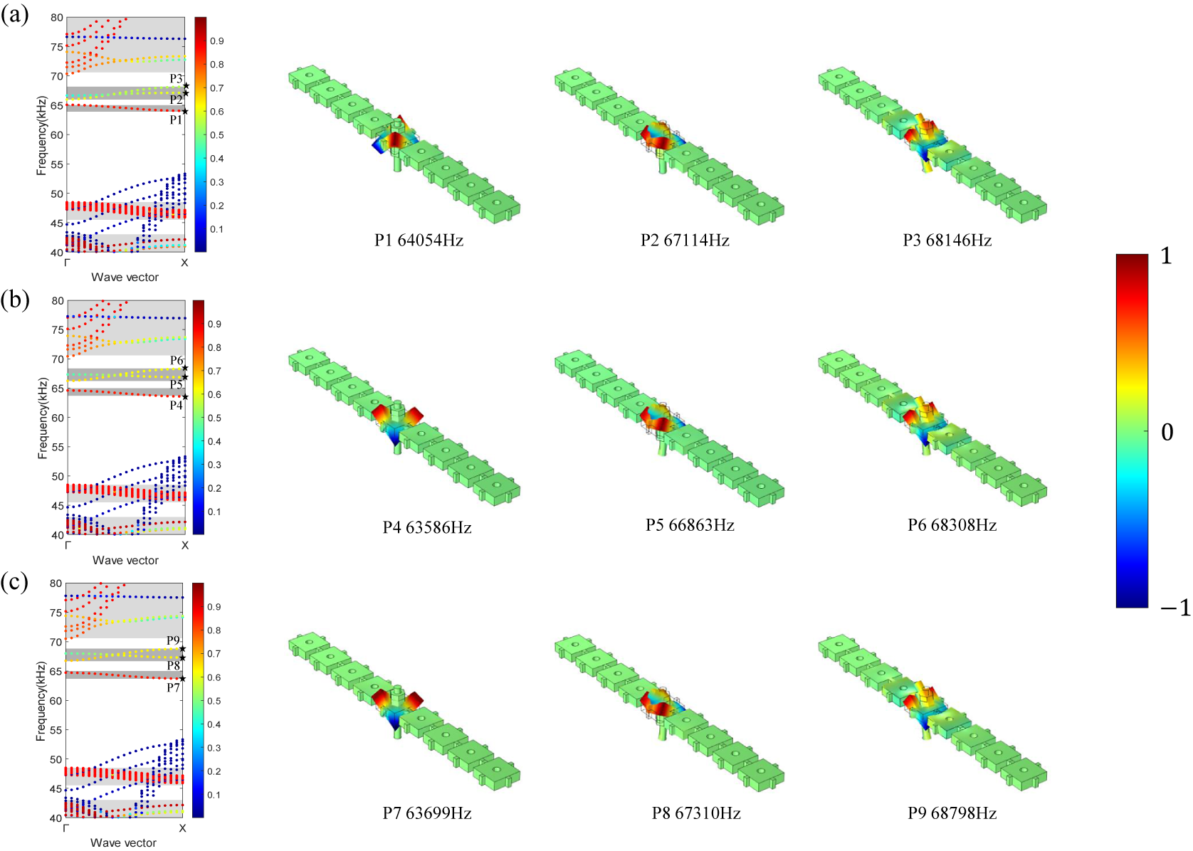
Figure 2b,c shows the band structures and vibration modes of the phononic waveguides with different prestrains. The two coupled defect bands shift upward with increasing prestrain. It seems, however, that the band structures and the bandgaps do not change significantly when prestrain is applied. This can be quantitatively identified by observing the eigenfrequency of the marked points. The vibration modes of the defect bands are similar to the case with perfect bond. The defect band around 65 kHz is almost independent of the prestrain because the threaded rod feels almost no vibrations (see the corresponding vibration modes at points P4 and P7). The vibration is asymmetric with respect to the wave propagation direction, so these two bands are deaf. This also holds for points P6 and P9. Only the guided modes P5 and P8 contribute to the transmission.
It is noted that the adjustment of prestress has a limited range in this paper. The stress of the rods cannot exceed the yield limit. Figure 3a,b shows the von Mises stress distribution of the structures with different prestrains. It is found that the stress is mainly concentrated on the rods. Under the two prestrains, the maximum von Mises stress in the rods are $3.4\times 10^8$
and
$3.4\times 10^8$
and $6.3\times 10^8$
N/m
$6.3\times 10^8$
N/m $^2$
, respectively. They are all within the yield limit of steel (
$^2$
, respectively. They are all within the yield limit of steel ( $6.9\times 10^8$
N/m
$6.9\times 10^8$
N/m $^2$
) (Rasmussen and Hancock, Reference Rasmussen and Hancock1995; Jiao and Zhao, Reference Jiao and Zhao2003; Wang et al., Reference Wang, Di, Zhang and Qin2021a). It is also valuable to study the case for prestress beyond the yield limit, that is, with the presence of plastic deformation. Relevant research will be conducted in future studies.
$^2$
) (Rasmussen and Hancock, Reference Rasmussen and Hancock1995; Jiao and Zhao, Reference Jiao and Zhao2003; Wang et al., Reference Wang, Di, Zhang and Qin2021a). It is also valuable to study the case for prestress beyond the yield limit, that is, with the presence of plastic deformation. Relevant research will be conducted in future studies.
Von Mises stress distribution of the supercells with different prestrains: (a) 0.0083 and (b) 0.0167.
Note: The structures around the rods are hidden. The colour scale represents the stress amount from 0 (green) to $6.3\times 10^8$
(red).
$6.3\times 10^8$
(red).

The above analysis shows that the defect bands appearing in the band gaps are sensitive to the prestrains. Waveguiding at different frequencies thus can be tuned by changing either the prestrains applied on the nuts or the geometric pattern of the defects.
Straight waveguide
In this subsection, we focus on wave propagation in straight waveguides with a length of 7 units. The simulation results for the transmission spectrum under different prestrains are given in Figure 4b,c. The result for perfect bond is given in Figure 4a. Three passing bands are clearly observed above 67 kHz. Their frequencies increase with increasing prestrain, consistently with the band structures shown in Figure 2. The transmission modes at the marked points of the transmission spectrum are given in Figure 4d. Elastic waves are clearly guided by the linear defects. It is also noted that the transmission around 65 kHz is relatively small, since the corresponding band is deaf.
Simulated transmissions of the straight waveguides with perfect bonds (a) or different prestrains: (b) 0.0083 and (c) 0.0167.
Note: Vibration modes at the corresponding labelled points are given in panel (d). The colour scale represents the normalized amplitude of out-of-plane displacements from 0 (blue) to 1 (red).

The experimental transmissions for the straight waveguides are given in Figure 5 for different prestrains (represented by torques measured by the Digital Torque Wrench). It can be observed that transmission near 67 kHz is apparent when the magnitude of the torque is 2.3 N $\cdot $
m. It gets more pronounced with increasing torque. The transmission modes at the labelled points are given in Figure 5d.
$\cdot $
m. It gets more pronounced with increasing torque. The transmission modes at the labelled points are given in Figure 5d.
Measured transmissions of the straight waveguides with different torques: (a) 2.3 N $\cdot $
m, (b) 2.7 N
$\cdot $
m, (b) 2.7 N $\cdot $
m, and (c) 3.0 N
$\cdot $
m, and (c) 3.0 N $\cdot $
m.
$\cdot $
m.
Note: Vibration modes at the corresponding labelled points are given in panel (d). The colour scale represents the normalized amplitude of out-of-plane displacements from 0 (blue) to maximum (red).

It can be observed that vibrations are clearly confined and guided along the linear defects around 67 kHz. These results are consistent with the numerical ones in Figure 4. It is also noted that there are passing bands around 57 kHz in the experimental spectrum. They correspond to the passing bands around 53 kHz in the numerical spectrum. Figure 2 shows that the modes around 53 kHz are the result of the coupling of in-plane and out-of-plane modes. Although the bands in Figure 2 are in-plane dominated, the coupled modes are excited in the experiments for the asymmetric excitation (see the vibration modes around 57 kHz in Figure 5d). Due to the coupling of the modes, the causes of frequency shift are complicated. In addition, there are other differences between numerical simulations and experimental measurements. When screwing the nuts in the experiments, it cannot be guaranteed that the force exerted by the nut on the rod is uniformly acting on the force area of the rod, which is not accounted for in the numerical simulation. Besides, the thread structures are not considered in the simulation. The observed differences may be attributed to all these contributions.
Simulated transmission properties of the bent waveguides (7 units) with perfect bonds (a) or different prestrains: (b) 0.0083 and (c) 0.0167.
Note: Vibration modes at the corresponding labelled points are given in panel (d). The colour scale represents the normalized amplitude of out-of-plane displacements from 0 (blue) to 1 (red).

Measured transmissions of the bent waveguides (7 units) with different torques: (a) 2.3 N $\cdot $
m, (b) 2.7 N
$\cdot $
m, (b) 2.7 N $\cdot $
m, and (c) 3.0 N
$\cdot $
m, and (c) 3.0 N $\cdot $
m.
$\cdot $
m.
Note: Vibration modes at the corresponding labelled points are given in panel (d). The colour scale represents the normalized amplitude of out-of-plane displacements from 0 (blue) to maximum (red).

Bent waveguide
In addition to the straight waveguide, tunability is also feasible for the design of other waveguides, such as waveguides with 90 $^{\circ }$
bend. The bent waveguide is composed of seven defected units. Transmission of the bent waveguide with perfect bond is given in Figure 6a. The results with different prestrains are given in Figure 6b,c. It is found that there is a passing band above 65 kHz for the waveguide with perfect bond, the frequency range of which is identical to that of the straight waveguide in Figure 4a. With the increase of prestain, passing band in the transmission spectrum shifts upward. Figure 6d shows the displacement distribution at the points marked on the passing bands in the transmission spectrum.
$^{\circ }$
bend. The bent waveguide is composed of seven defected units. Transmission of the bent waveguide with perfect bond is given in Figure 6a. The results with different prestrains are given in Figure 6b,c. It is found that there is a passing band above 65 kHz for the waveguide with perfect bond, the frequency range of which is identical to that of the straight waveguide in Figure 4a. With the increase of prestain, passing band in the transmission spectrum shifts upward. Figure 6d shows the displacement distribution at the points marked on the passing bands in the transmission spectrum.
Simulated transmission properties of the wave splitter with perfect bonds (a) or different prestrains: (b) 0.0083 and (c) 0.0167.
Note: Transmissions collected on the right and left outputs are marked by blue and red, respectively. Vibration modes at the corresponding labelled points are given in panel (d). The colour scale represents the normalized amplitude of out-of-plane displacements from 0 (blue) to 1 (red).

Measured transmissions of the wave splitter with different torques: (a) 2.3 N $\cdot $
m, (b) 2.7 N
$\cdot $
m, (b) 2.7 N $\cdot $
m, and (c) 3.0 N
$\cdot $
m, and (c) 3.0 N $\cdot $
m.
$\cdot $
m.
Note: Transmissions measured on the right and left outputs are marked by blue and red, respectively. Vibration modes at the corresponding labelled points are given in panel (d). The colour scale represents the normalized amplitude of out-of-plane displacements from 0 (blue) to maximum (red).

Energy is observed to propagate easily through the bend. We further performed experimental measurements on the bent waveguide with different prestresses. The transmission and displacement distributions are shown in Figure 7. A passing band is clearly found in the transmission spectrum above 65 kHz. With increasing prestress, the passing band moves upward, consistently with the numerical results in Figure 6. But the frequency ranges do not change too much, possibly due to the gap between threaded holes and rods in the experiment. The waveguide phenomenon can be observed in all the displacement fields extracted in the experiment in Figure 7d. A similar phenomenon is also observed around 55 kHz, identical to the experimental results in Figure 5 for the straight waveguide.
Wave splitter
In addition, we also fabricated a wave splitter in the plate with the aid of reconfigurability.
Figures 8 and 9 give the simulated and experimental transmissions and displacement distributions for wave splitter with different prestrains. The wave source is applied on the top part of the splitter. Transmissions to the left and right output of the splitter are almost identical, suggesting that the wave amplitude is equally split (Wang et al., Reference Wang, Wang, Wang and Laude2017b). This also holds for the experimental transmissions in Figure 9. With increasing prestress, the passing bands in the transmission spectrum shift upward. Wave splitting can be observed in the displacement fields extracted under the three different prestresses for both simulations and experiments.
Conclusions
In this paper, we have investigated the manipulation of Lamb waves in dual tunable waveguides formed on a phononic plate. Straight waveguides, bending waveguides, and wave splitters were studied. Dual tunability was achieved through the distribution of threaded rods fixed with nuts and the assembly prestress of nuts. Numerical and experimental results show that the introduction of threaded rods with nuts can form different waveguides in the plate and control the wave propagation. By controlling the amount of prestress, the frequency range of the passing band can be adjusted. The larger the prestress, the more the frequency range of the passing band moves toward high frequencies. This phenomenon occurs in straight waveguides, bending waveguides, and wave splitters.
This paper is relevant to the practical application of elastic acoustic devices. With the aid of control elements, the geometric pattern and applied prestress between nuts and plates can be tuned in a programmable way. Active and even smart controls of elastic waves are expected.
Data availability statement
Data in this article are available upon request.
Acknowledgements
The authors wish to thank Dr. Shuai Yang for his help in the numerical simulation.
Author contribution
W.G. and Y.-K.M. contributed equally to this work.
Funding statement
Financial supports by the National Key R&D Program of China (Grant No. 2022YFB3806101), the National Natural Science Foundation of China (Grant Nos. 12122207, 12021002, and 11991032), and the EIPHI Graduate School (Grant No. ANR-17-EURE-0002) are gratefully acknowledged.
Competing interest
The authors declare that they have no known competing financial interests.


 Open access