


1. Introduction
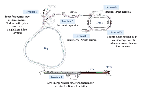
In China, the Heavy Ion Research Facility at Lanzhou (HIRFL) [Reference Wen, Zhan and Wei1, Reference Wen, Zhan and Wei2] is one major national research facility focusing on nuclear physics, atomic physics, heavy ion applications, and interdisciplinary research. A series of remarkable results have been obtained at HIRFL [Reference Tu, Xu and Wang3–Reference Zhao, Sun and Wang8]. Based on the effective construction and successful operation of HIRFL [Reference Yuan, Gao and Ma9], a new facility named High-Intensity Heavy-Ion Accelerator Facility (HIAF) [Reference Yang, Xia and Xiao10] has been proposed and designed by the Institute of Modern Physics (IMP), Chinese Academy of Sciences (CAS), in 2009. As indicated in Figure 1, the HIAF comprises a SECR (superconducting electron-cyclotron-resonance ion source) [Reference Zhao, Sun and Guo11], a superconducting iLinac [Reference Wang, He and Jia12], a high-intensity synchrotron BRing (booster ring) [Reference Yang, Xia and Xiao10], a multifunction high-precision synchrotron SRing (spectrometer ring) [Reference Wu, Yang and Xia13], and a superconducting radioactive beam line HFRS (fragment separator) [Reference Sheng, Zhang and Zhang14] to connect the two rings. As a more powerful facility, HIAF can provide intense primary and radioactive ion beams for nuclear physics [Reference Ye, Yang, Yang and Han15–Reference Guo, Liu, Tang, Li and He17], plasma physics [Reference Zhao, Zhang and Cheng18], atomic physics [Reference Ma, Zhang, Wen and Huang19], and related research fields.
General layout of HIAF.
The BRing, as the key part of the HIAF, has been designed to accumulate and accelerate heavy-ion beams to high intensity and energy with high efficiency, and the important parameters are listed in Table 1. To realize these purposes, it is necessary to control the emittance growth and beam loss to an allowable level of each process including capture, acceleration, and an additional bunch merging. In this paper, we take 238U35+, which can be accelerated up to roughly 830 MeV/u corresponding to the maximum magnetic rigidity of 34 Tm, as an example to study the longitudinal beam dynamics by theoretical calculation and numerical simulation. The numerical model is given by a scalable multi-macroparticle simulation platform CISP [Reference Liu, Yang and Xia20], and 10000 macroparticles are applied during the simulation process. In order to quantify the beam properties during the whole processes, several outputs such as energy, momentum, rms emittance, rms bunch length, space charge voltages, bunching factor, and RF amplitude ramps are plotted as a function of time or revolution turn.

The content is organized as follows: in Section 2, we calculate the basic RF program for beam capture, the beam ions’ distribution evolution in the phase space is simulated, and the beam properties are derived; meanwhile, the space charge effect on longitudinal emittance growth is discussed; in Section 3, the basic RF program for beam acceleration is calculated, and the beam properties are derived by simulations; and in Section 4, the bunch merging processes are studied, and the basic RF program is given. Meanwhile, the beam properties under RF errors and injection energy fluctuation are dictated, and the tolerance on these errors based on the emittance growth and beam loss is presented; the results can be found in Appendixes A and B.
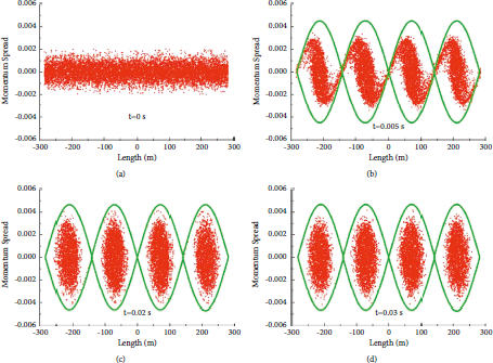
After two-plane painting injection and accumulation, the realistic particle distribution of 238U35+ with an energy of 17 MeV/u is shown in Figure 2, a plot, the horizontal axis is circumference L in units of meter (m), and the vertical axis is momentum spread Δp/p. As can be seen, the beam is completely unbunched, and the rms relative momentum spread is 0.667 × 10⁻³. To accelerate the 238U35+ beam from 17 MeV/u to 830 MeV/u with minimum longitudinal emittance growth and beam loss, a detailed understanding of the longitudinal beam dynamics during capture and acceleration is necessary. Moreover, in our case, an additional multibunch merging process converting four bunches into one is also needed.
Beam ion distributions in the phase space before (a) and after capture with tc = 0.005 s (b), 0.02 s (c), and 0.03 s (d). In all cases, the RF voltage is ramped from Vi = 0.1 kV to Vc = 30.29 kV. The bucket separatrix is drawn in green.
2. Beam Capture at Injection Energy
When accelerating the heavy-ion beam in a synchrotron, the bunched beam is needed, which can be accomplished through the capture [Reference Lee21–Reference Eliseev, Meshkov, Mikhailov and Sidorin23]. As one of the potential sources for longitudinal beam quality degradation and beam loss, beam capture requires three principles: (i) the capture must be optimized to keep any beam loss to a minimum to ensure beam intensity and to reduce the radioactive contamination of the machine; (ii) the capture duration should be as short as possible to reduce the machine cycle period, and (iii) the growth of longitudinal emittance ε at the end of capture should be minimal since the growth of ε will increase the demands on the RF system. The RF voltage program V(t) [Reference Lee21] for beam capture is determined by the following equation:
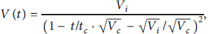
where Vi and Vc are the initial and final voltage amplitude in the RF cavity, respectively, and tc is the capture time. Vi, which is the activation value of different electronic circuits in the RF system, is chosen in such a way that the corresponding bucket area generated by it should be much smaller than ε of the initial injected costing beam. The voltage Vc must provide a sufficient bucket area to enclose ε. tc should be large enough compared to the period of the synchronous oscillation to make a linear variation of the phase space parameters, which will help to preserve ε throughout the capture process.
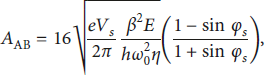
For the 238U35+ beam at the BRing, the revolution frequency is 0.10 MHz at 17 MeV/u, which is far lower than the lower limit of the working frequency of the RF cavity, the RF cavity has to work in the fourth harmonic (h = 4) of the revolution frequency according to the design, then, the coasting beam will be captured in four stationary buckets, and four bunches will be generated. In general, the stationary bucket generated by Vc according to the following equation (2) [Reference Lee21] should be 1.5 times of ε.
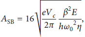
where e is the charge, β = v/c, in which v is the velocity of particle moving, E is the energy of the synchronous particle, integer h is known as the harmonic number, ω 0 is the angular revolution frequency, and η is the phase-slip factor. In this case, ε in the phase space (ϕ, ΔE/ω0) is 323 eVs, the stationary bucket A SB should be 485 eVs, and the capture voltage Vc of 30.29 kV will be required.
First, simulations of the capture, with different tc from 0.005 s to 0.035 s with a step of 0.005 at Vc = 30.29 kV, were performed without any errors of the RF and injection energy fluctuation. In these cases, Vi is chosen to be 0.1 kV, and the beam ion distributions in the phase space at the end of capture with different tc are shown in Figure 2. The rms momentum spread Δp/p rms and the rms longitudinal emittance ε rms [Reference Lee21] are qualitatively derived, which are shown in Figure 3.
Δp/p rms (black) and ε rms (red) at the end of capture with tc =0.005 s, 0.01 s, 0.015 s, 0.02 s, 0.025 s, 0.03 s, and 0.035 s at Vc = 30.29 kV.

As can be seen from Figure 3, Δp/p rms is ranged from 0.00149 to 0.00157, which is very similar to each other; however, ε rms decreases from 70.36 eVs to 53.04 eVs as tc increases from 0.005 s to 0.035 s; among them, ε rms of about 55 eVs is almost irrespective of tc when tc ≥ 0.002 s. The maximum ε rms of 70.36 eVs occurs when tc = 0.005 s; the reason is the very rapid RF voltage ramping leading to beam filamentation. To balance ε rms and the duration of the machine cycle, tc of 0.02 s will be applied in the capture process.
Apart from tc, Vi is also a critical parameter to be controlled. Simulations were also performed for Vi from 0.08 kV to 0.14 kV with a step of 0.01 at Vc = 30.29 kV and tc = 0.02 s, and ε rms are derived which are shown in Figure 4. The minimum ε rms occurs when Vi = 0.11 kV.
ε rms at the end of capture with Vi = 0.08 kV, 0.09 kV, 0.1 kV, 0.11 kV, 0.12 kV, and 0.13 kV at Vc = 30.29 kV and tc = 0.02 s.
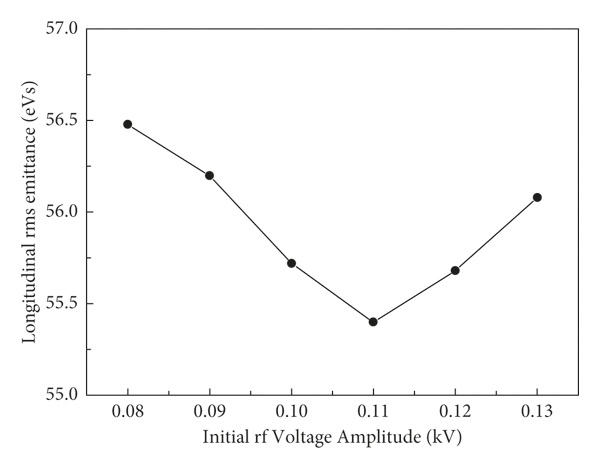
If Vc is below 30.29 kV, the generated stationary bucket area cannot constrain the injected beam completely, and the beam loss will be inevitable. On the contrary, Vc higher than 30.29 kV will induce large momentum spread which may exceed the limited momentum acceptance of the BRing, and the additional beam loss may occur. After a series of calculation, simulation, and optimization, Vi = 0.11 kV, Vc = 30.29 kV, and tc = 0.02 are determined for 238U35+ beam capture. Δp/p rms of the captured beam is 0.0015, and almost all particles can be captured after 1984 machine turns.
For the 238U35+ beam, the designed intensity will exceed 3.0 × 10¹⁰. Such high beam intensity in the BRing is expected to cause an additional collective effect. As one of the important high beam intensity effects, the space charge [Reference Lee21, Reference Boine-Frankenheim24, Reference Spiller, Blasche, Hülsmann, Krämer, Ramakers and Reich-Sprenger25] plays an important role for the beam dynamics especially. The equation of the longitudinal phase space motion indicates the dependence of particle distribution on the time variations of the RF field, and this external RF field, or voltage, is modified by the field due to the space charge, which consequently modifies the particle distribution and eventually leads to the beam loss or beam quality degradation.
The space charge is an important issue only in low- and medium-energy accelerators because the space charge voltage per turn scales to 1/βγ 2. In this paper, the space charge effect with various beam intensities N ranging from 3.0 × 10¹⁰ to 1.0 × 10¹¹ at the end of capture was estimated, and Δp/p rms and ε rms are derived, which are shown in Figure 5.
Δp/p rms (black) and ε rms (red) with different N = 3.0 × 10¹⁰, 4.0 × 10¹⁰, 5.0 × 10¹⁰, 6.0 × 10¹⁰, 7.0 × 10¹⁰, 8.0 × 10¹⁰, 9.0 × 10¹⁰, and 1.0 × 10¹¹.
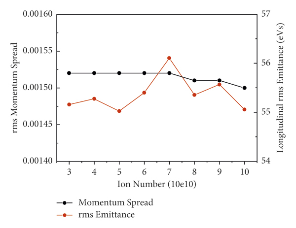
It is concluded that the maximum ε rms of 56.10 eVs occurs when N = 7.0 × 10¹⁰, which is increased only by 1.71% than the case of N = 3.0 × 10¹⁰. So, the space charge effect on the emittance growth is insignificant if the beam intensity is less than 1.0 × 10¹¹.
3. Beam Acceleration
After capture, the stationary buckets will be transformed into moving ones to start acceleration through synchronous phase shifting [Reference Lee21, Reference Rybarcyk26, Reference Hotchi, Kinsho and Hasegawa27]. Since the ionization cross sections and space charge effect decrease largely with the increase of beam energy, the injected low-energy heavy-ion beam should be accelerated to high energy as fast as possible to minimize the significant ionization beam loss, stabilize the dynamic residual gas pressure, and suppress the strong space charge effect; then, a rapid acceleration with a maximum bend magnetic field ramping rate over time
 of 12 T/s is proposed.
During the beam acceleration process, the moving bucket area which is determined by equation (3) should remain approximately invariant of around 485 eVs in (ϕ,
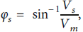
 ). The required voltage amplitude Vs and synchronous phases φ s for the RF acceleration system can be calculated with the following equations (3) and (4) [Reference Lee21]:
in which
 is the voltage that is used to keep the synchronous particle on its ideal orbit, L is the circumference of the BRing, ρ is the bending radius of the dipole magnet, B ˙ is the ramping rate of the dipole magnetic field over time,
 is the maximum value of
 available, Vs and φ s are the needed voltages and synchronous phases, respectively, and E is the particle kinetic energy which is B-dependent. The acceleration cycle will be divided into three stages based on
 . The first stage is
 increasing from 0 T/s to the maximum value of 12 T/s in 0.05 s, which is determined by hardware equipment such as the magnet and power supply. The second stage is the process of B increasing with constant
 of 12 T/s. The third stage is B increasing to the required value while
 decreasing from 12 T/s to 0 T/s in 0.05 s. After the three stages, B will increase from 0.18 T corresponding to the injection energy of 17 MeV/u to 1.58 T corresponding to the extraction energy of 830 MeV/u. The programmed
 (green solid line) and B (green short dot line) curves are shown in Figure 6. Similarly, Vs and φ s are divided into three stages. At the first stage, Vs increases from 30.29 kV up to its maximum amplitude of 268.00 kV, and φ s increases from 0 rad to 0.58 rad, and in this stage, E rises from 17 MeV/u to 108.87 MeV/u. At the second stage, Vs drops from 268.00 kV to 212.24 kV, and φ s continues to increase from 0.58 rad to 0.764 rad, and in this stage, E rises from 108.87 MeV/u to 595.91 MeV/u. At the last stage, Vs continues to drop from 212.24 kV to 4.52 kV, and φ s drops from 0.764 rad to 0 rad, and in this stage, E rises from 595.91 MeV/u to 830 MeV/u, and the acceleration efficiency is nearly 99%.
RF voltage programs V and φ s of the RF cavity at different operating frequencies, B,
 , and E during the whole process from capture to bunch merging. Black solid line and black short dash dot line are Vsand φsof the main RF cavity with f = 1.79 MHz (h = 4), respectively. Red solid line and blue solid line are V 2 and V 3, respectively. Beam capture: 0–0.02 s; acceleration: 0.02–0.1856 s; the 4 : 2 bunch merging: 0.1856–0.2106 s; the 2 : 1 bunch merging: 0.2106–0.2406 s.

4. Multiple Bunch Merging at the Extraction Energy Platform
After acceleration, a 4 : 2 and 2 : 1 two-step bunch merging [Reference Zipfel, Klingbeil, Laier, Ningel and Thielmann28, Reference Bozsik, Hofmann and Jahnke29] process will be used to transform four bunches into one to meet the extraction requirement. The first step is to merge four bunches into two bunches; during this step, the voltage amplitude of one RF cavity operating at h = 4 and the frequency f 1 = 1.79 MHz is decreased linearly from V 1 = 4.52 kV to 0.10 kV over merging time t; concurrently, the voltage amplitude of another RF cavity operating at h = 2 and the frequency f 2 = 0.895 MHz is increased linearly from 0.10 kV to its final value V 2. t and V 2 will affect the longitudinal emittance ε of the merged bunches, and it will inevitably further affect the following 2 : 1 bunch merging. The simulations, with different t from 0.005 s to 0.035 s with a step of 0.005 at different V 2 = 1 kV, 2 kV, and 3 kV, are performed, and ε rms and beam loss are derived, which are shown in Figure 7(a). The second step is to merge two bunches into one. In this step, V 2 is decreased linearly from 2 kV to 0.10 kV over time t 2; meanwhile, the voltage of the RF cavity working at h = 1 is increased linearly from 0.10 kV to V 3. The ε rms dependence on t 2 ranging from 0.005 s to 0.035 s and with different V 3 = 1 kV, 2 kV, and 3 kV is derived, which is shown in Figure 7(b).
ε rms with different merging times at V 2 = 1 kV (red), 2 kV (blue), and 3 kV (green) at the end of 4 : 2 bunch merging (a) and 2 : 1 bunch merging (b).

According to the 4 : 2 bunch merging simulation result, it was found that ε rms tends to decrease with the increase of t; however, when t is greater than 0.025 s, ε rms tends to be fixed at around 60 eVs. So, the RF program of t = 0.025 s and V 2 = 2 kV for the 4 : 2 bunch merging step is determined, the phase φ s is fixed at −1.571 rad, the beam distribution in the longitudinal phase space is shown in Figure 8(a), and ε rms is 60.19 eVs.
Beam ion distributions in the phase space at the end of the 4 : 2 bunch merging (a) and the 2 : 1 bunch merging (b).

For the 2 : 1 bunch merging simulation result, it can be known that ε rms decreases with the increase of t 2, and similar results are obtained with V 3 = 2 kV and 3 kV. However, ε rms increases with the increase of V 3, so the RF program of t 2 = 0.03 s and V 3 =1 kV is determined, the phase φ s is fixed at 0.785 rad, the beam distribution in the longitudinal phase space is shown in Figure 8(b), and ε rms is 60.19 eVs.
5. Conclusion
The whole process for 238U35+ from beam capture to bunch merging takes about 0.24 s, and the total beam loss does not exceed 1%. The RF acceleration system is designed with a total peak voltage of about 268 kV, composed of 7 RF cavities, and the frequency range is from 0.39 MHz to 1.79 MHz.
The beam parameters obtained in this study will not only provide the basis for the design of the extraction elements of the BRing, such as kicker and electrostatic septum, but also for the injection element of the SRing.
Appendix
A. Effect on Beam Dynamics with RF Errors
The longitudinal beam manipulation can be done by the RF cavity, the calculated RF program due to the idealized RF character differs from the operating conditions, and many inevitable errors such as RF phase and amplitude field will lead to the change of the beam distribution in the phase space. In this paper, further studies were performed by using the numerical simulations to estimate the impact of RF phase and amplitude field errors on the beam longitudinal emittance growth and possible resulting beam loss by CISP. The results in turn dictate the tolerances on these errors.
The simulations, with different synchronous random phase errors ranging from Δφ =1° to 5° with a step of 1 at different random amplitude errors ΔV/V = 0.01%, 0.02%, 0.03%, and 0.04%, are performed, and ε rms at the end of capture (red solid line), at the end of the 4 : 2 bunch merging (blue solid line), and at the end of the 2 : 1 bunch merging (green solid line) and the total efficiency (black solid line) are derived, which are shown in Figure 9.
ε rms and efficiency vs. RF field errors in phase (Δφ=1°, 2°, 3°, 4°, and 5°) and in amplitude (ΔV/V): (a)ΔV/V = 0.01%; (b)ΔV/V = 0.02%; (c)ΔV/V = 0.03%; (d)ΔV/V = 0.04%.
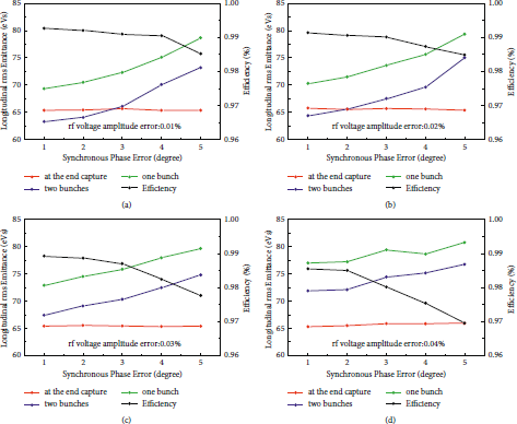
The simulation results show that the difference of the ε rms growth at the end of capture is only 1.00% between the cases with the RF field errors Δφ = 5° and ΔV/V = 0.04% than the idealized RF program, but the difference of the ε rms growth at the end of the 4 : 2 bunch merging and at the end of the 2 : 1 bunch merging is 21.12% and 16.52% with the same RF field error mentioned above; meanwhile, the total efficiency can only reach 96.97%, which is far beyond the design requirement. To ensure the total beam loss below 1%, the combined RF field errors of
 2° in phase and ΔV/V = 0.02% in amplitude are needed.
B. Effect on Beam Dynamics with Energy Fluctuation
The injected energy fluctuation ΔE during the two-plane painting injection will lead to the mismatch to the synchronous energy of the BRing, which will cause the increase of energy spread, and then beam loss may occur due to the insufficient bucket area when the calculated RF program is ramped. Effects of ΔE/E on the emittance growth and beam loss were numerically investigated by CISP, and the results are shown in Figure 10.
ε rms and efficiency vs. ΔE/E = 0.01, 0.02, 0.03, 0.04, and 0.05.

The injected beam energy fluctuation has a great influence on ε rms not only after capture but also after the 4 : 2 bunch merging and the 2 : 1 bunch merging, and it also has a great impact on efficiency. To ensure the efficiency is not less than 99%, ΔE/E shall not exceed 0.01%.
Data Availability
The data used to support the findings of this study are available from the corresponding author upon request.
Conflicts of Interest
The authors declare that they have no conflicts of interest.


 Open access